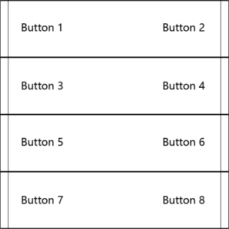
The parameter settings in the ETS system are described by functional blocks.
Application
Application | Max. Communication Objects | Max. Group Addresses | Max. Association Tables |
|---|---|---|---|
2/4/6/8-Button Scene Panel | 850 | 1700 | 1700 |
Button Mapping
The following explains the correspondence between the smart panel’s physical buttons and the button channels defined in the database:
NOTE:
On multi-rocker panels, “for Up of Rocker” in the database refers to the left button, and “for Down of Rocker” refers to the right button.
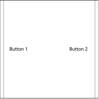
1-rocker panel: Corresponds to Button 1 and Button 2.
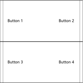
2-rocker panel: Corresponds to Button 1, Button 2, Button 3, and Button 4.
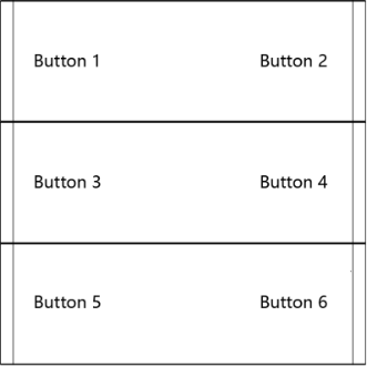
3-rocker panel: Corresponds to Button 1, Button 2, Button 3, Button 4, Button 5, and Button 6.
4-rocker panel: Correspond to channel Button 1, Button 2, Button 3, Button 4, Button 5, Button 6, Button 7, and Button 8.