Version: 1.0 | Date: Jan.2021
About This Manual
Thank you for choosing Akuvox A092 series access controller. This manual is intended for the administrators who need to properly configure the access controller. This manual applies to the version 92.30.1.6, and it provides all the configurations for the functions and features of Akuvox access control. Please visit Akuvox forum or consult technical support for any new information or latest firmwares.
Introduction of Icons and Symbols
Warning:
- Always abide by this information in order to prevent the persons from injury.
Caution:
- Always abide by this information in order to prevent the damages to the device.
Note:
- Informative information and advice from the efficient use of the device.
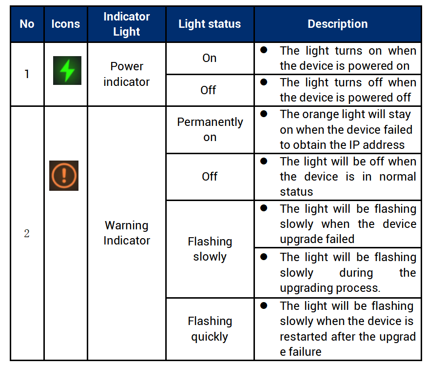
LED Indicator Light Status
1.Product Overview
Akuvox A092 series access controller is Linux-based. It has multiple ports, such as RS485 and Wiegand ports that can be used to easily integrate with external digital systems, such as card readers, elevator controller and fire alarm detector, helping to create a holistic control of building entrance and its surroundings. With the two in-built relays, A092 is capable of controlling two doors maximum while giving you a great sense of security via card access. A092 is applicable to such applications as commercial buildings, hospital buildings and warehouses.
2. Access the Device
Akuvox A092 access controller system settings can be accessed on the device web interface.
2.1. Obtain Device IP Address
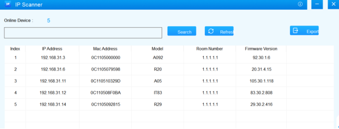
To access the device web interface, you need to obtain the device IP address using Akuvox IP scanner. You can just click Search to find the device IP address
2.2. Access the Device Web Interface
Enter the device IP address on the web browser in order to log in the device web interface where you can configure and adjust parameters etc. The Initial user's name and password are “admin” and please be case-sensitive to the user names and passwords entered.

Note:
- Google Chrome browser is strongly recommended.
3. Language and Time Setting
3.1. Language Setting
When you first set up the device, you might need to set the language to your need or you can do it later if needed. You can go to Setting>Time/Lang on the device web interface.
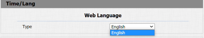
- Type: choose a suitable web interface language. Normally, English is default web language.
3.2. Time Setting
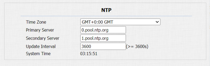
You to set up the NTP (Network Time Protocol) server address that you obtained to automatically synchronize your time and date. And when your time zone is selected, the device will automatically notify the NTP server of its time zone in order that the NTP server can synchronize the time zone set-up in your device. You can go to Setting > Time/Lang > NTP for the setting.
Parameter Set-up:
- Time Zone: select the specific time zone depending on where the device is used and then press Confirm tab for the confirmation. The default time zone is GMT GMT+0.00.
- Primary/Secondary Server: the time zone server, normally it will automatically obtain the time when connecting to the network. The secondary server will take effect while the primary server is invalid.
- Update Interval: to configure interval between two consecutive NTP requests.
- System: system is the current device system time, which is in 24-hour format by default.
4. Network Configuration
4.1. Network Status
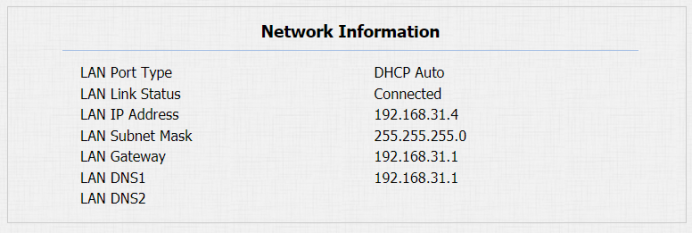
To check the network status, you can go to Status > Network Information on the device web interface.
4.2. Device Network Configuration
You can check for the device’s network connection info and configure the default DHCP mode (Dynamic Host Configuration Protocol) and static IP connection for the device. To do so , you can go to Network > Basic on the device web interface.

Parameter Set-up:
- DHCP: select the DHCP mode by moving the toggle switch to the right. DHCP mode is the default network connection. If the DHCP mode is turned on, then the access controller will be assigned by the DHCP server with IP address, subnet mask, default gateway, and DNS server address automatically.
- Static IP: select the static IP mode by checking off the DHCP check box. When static IP mode is selected, then the IP address, subnet mask, default gateway, and DNS servers address have to be manually configured according to your actual network environment.
- IP Address: set up the IP Address if the static IP mode is selected.
- Subnet Mask: set up the subnet Mask according to your actual network environment.
- Default Gateway: set up the correct gateway default gateway according to the IP address of the default gateway.
- LAN DNS1/2: set up preferred or alternate DNS Server (Domain Name Server) according to your actual network environment. Preferred DNS server is the primary DNS server address while the alternate DNS server is the secondary server address and the access controller will connect to the alternate server when the primary DNS server is unavailable.
4.3. Configure Web Server
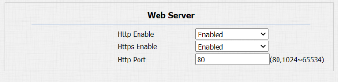
You can configure the device web server by setting up the http and https protocols as well as the http port for accessing the device web interface. You can go to the Network > Advanced> Web Server on the web interface for the setting.
Parameter Set-up:
- Http Enable: enable it if you allow the device web interface to be accessed via http protocol, or disable it if you want to deny the access via http. Enabled is the default setting.
- Https Enable: enable it if you allow the device web interface to be accessed via https protocol, or disable it if you want to deny the access via https. Enabled is the default setting.
- Http Port: specify the web server http port for accessing the device web interface via Http/Https.
4.4.TR069
TR-069 (Technical Report 069) is the document number of the technical report, defined by the Broadband Forum, that specifies the “CPE WAN management protocol” or CWMP. It defines an application layer protocol for remote management of end-user devices. As a bidirectional SOAP/HTTP-based protocol, it provides the communication between Customer-Premises Equipment (CPE) and Auto-Configuration Servers (ACS). It includes both a safe auto configuration and the control of other CPE management functions within an integrated framework.

Parameter Set-up:
- Active: enable it when you want to activate the TR069 function on the ACS server side.
- Version: select the TR069 version.
- ACS URL: enter the URL of the ACS server, for example: “http://192.168.1.47:8080/openacs/acs"
- User Name: enter the ACS server user name for the authentication.
- Password: enter the ACS server authentication password.
- Active: enable it if you allow the device to send requests to the ACS server for the automatic configuration and update etc.
- Periodical Interval: select the time interval for the device to send the request to the ACS server for the automatic configuration and update etc.
- URL: enter the device URL, for example: http://192.168.1.48:8882/。
- User Name:enter the device authentication user name.
- Password: enter the device authentication password.
4.5. SNMP
SNMP (Simple Network Management Protocol) is an Internet-standard protocol for managing devices on IP networks. SNMP is widely used in network management system to monitor network-attached devices for conditions that may draw network administrative attention. SNMP exposes management data in the form of variables on the managed systems, which describe the system configuration. These variables can then be queried by managing applications. These variables accessible via SNMP are organized in hierarchies, which are described by Management Information Bases (MIBs).

Parameter Set-up:
- Active: enable or disable the SNMP function. The default setting is Disabled.
- Port: Specific the port for the data transmission from 1024-65535.
- Trusted IP: enter the third-party IP address.
5. Relay Setting
5.1. Configure Built-in Relay
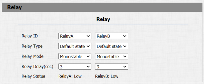
A092 access controller has two built-in relays that can be connected to the electrical door locks for the door access control. You can go to Access control > Relay for the setting.
Parameter Set-up:
- Relay ID: you are allowed to set up two relay switches in total for the door access control (Relay A, Relay B)
- Relay Type: there are two relay types: default state (high voltage level, NC-normally closed) and inverted state (Low voltage level, NO-normally open). Default state changes from NC-NO, Inverted state is from NO-NC.
- Relay Mode: select Monostable or Bistable. When you select Monostable, the relay will reset after the door opening which means the door will be closed again, however, if you select Bistable, then the relay will not reset and you have to for example, swipe the card on the card reader to close the door.
- Relay Delay: set the relay delay timing (Ranging from 1-10 Sec.) For example, if you set the hold delay time as “5” Sec. then the relay will be delayed for 5s after the door is unlocked.
- Relay Status: relay status is low by default which means normally closed (NC) If the relay status is high, then it is in Normally Open status (NO).
5.2. Configure Web relay
In addition to the built-in relays, you can also unlock the door that is connected to web relay. You can go to Access Control > Web Relay/Web Relay Action Setting to configure the web relay.

Parameter Set-up:
- Type: select “Webrelay” to enable the web relay. Select Disable to disable the web relay. Select Both to enable both local relay and web relay.
- IP Address: enter the web relay IP address provided by the web relay manufacturer.
- User Name: enter the User name provided by the web relay manufacturer.
- Password: enter the password provided by the web relay manufacturer. The passwords is authenticated via HTTP and you can define the passwords using “http get” in Action.
- Web Relay Action: enter the specific web relay action command provided by the web manufacturer for different actions by the web relay.
Web Relay Extension: enter the relay extension information, which can be a SIP number of an intercom device such as an indoor monitor, so that the specific action command will be sent when unlock is performed on the intercom device.
6. Door Access Schedule Management
You are required to configure and make schedule for the user-based door access via RF card etc.
6.1. Configure Door Access Schedule
You can create door access schedules so that they can be later conveniently applied to the door access control intended for individual user or a group of users created. Moreover, you can edit your door access schedule if needed.
6.1.1. Create Door Access Schedule
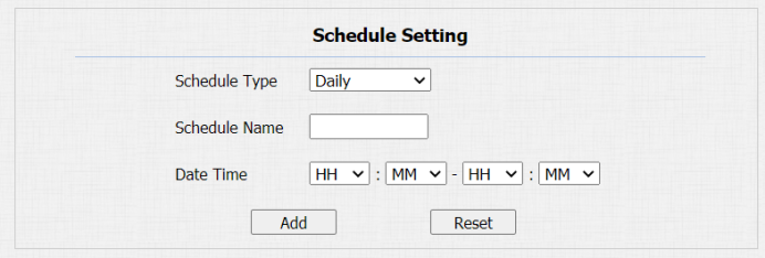
You can create the door access schedule on the daily or monthly basis and you can also create schedule that allows you to plan for a longer period of time in addition to running the door access schedule on the daily, weekly basis or longer period. You can go to Access Control > Schedules > Schedule Setting for the setting.
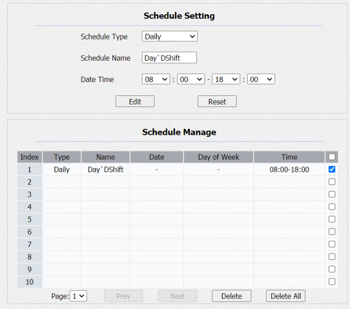
- To create a daily schedule
 Parameter Set-up:
- Schedule Type: select “Daily” Type if you to run the door access control on the daily basis.
- Schedule Name: create a door access schedule name
- Data Time: Set up the time schedule for the validity of the door access during a day.
- To create a weekly schedule
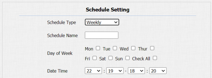
- Schedule Type: select “Weekly” Type if you to run the door access control on the daily basis.
- Schedule Name: create a door access schedule name.
- Day of week: select the day (s) on which door access can be valid on a weekly basis
- Date Time: Set up the time schedule for the validity of the door access during a day.
- To create a longer period schedule
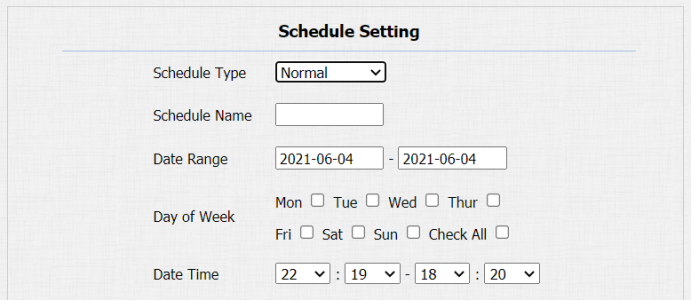
- Schedule Type: select “Weekly” Type if you to run the door access control on the daily basis.
- Schedule Name: create a door access schedule name.
- Date Range: set the start day and end day of the schedule.
- Day of week: select the day (s) on which door access can be valid on a weekly basis
- Data Time: Set up the time schedule for the validity of the door access during a day.
6.2. Import and Export Door Access Schedule
In addition to creating door access schedule separately, you can also conveniently import or export the schedules in order to maximize your door access schedule management efficiency. To import and export the schedule You can go to Access Control > Schedules > Import/Export Schedules(.xml) on the web interface.
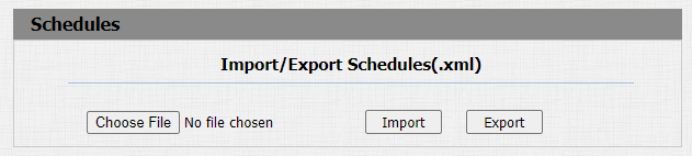
Note:
- It only supports .xml format file for importing and exporting the schedule.
6.3. Edit the Door Access Schedule
If you want to edit or delete your door access schedule you created, you can edit or delete the selected configured schedule separately or in batch on the web interface. To do so, you can go to Access Control > Schedules Setting/Schedule Manage on the web interface.
7. Door Unlock Configuration
7.1. Configure Access Card Format
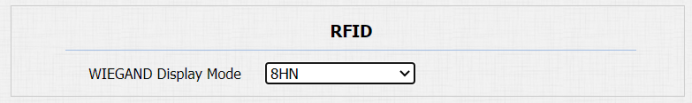
If you want to integrate with the third-party intercom system in terms of RF card door access, you can change the RF card code format to be identical with that applied in the third-party system. You can go to Access Control > Card Setting > RFID on the web interface.
Parameter Set-up:
- WIEGAND Display Mode: select the card format for the WIEGAND Card for the door access among five format options: 8H10D, 6H3D5D(W26), 6H8D, 8HN; 8HR, 6H3D5D-R(W26), and RAW. The card code format is 8HN by default in the access controller.
7.2. Configure Access Card for Door Unlock
On the device web interface, you can not only configure the RF card one by one manually but also import or export the RF card files to the device in batch in order to maximize card configuration efficiency.
- Configure RF card manually
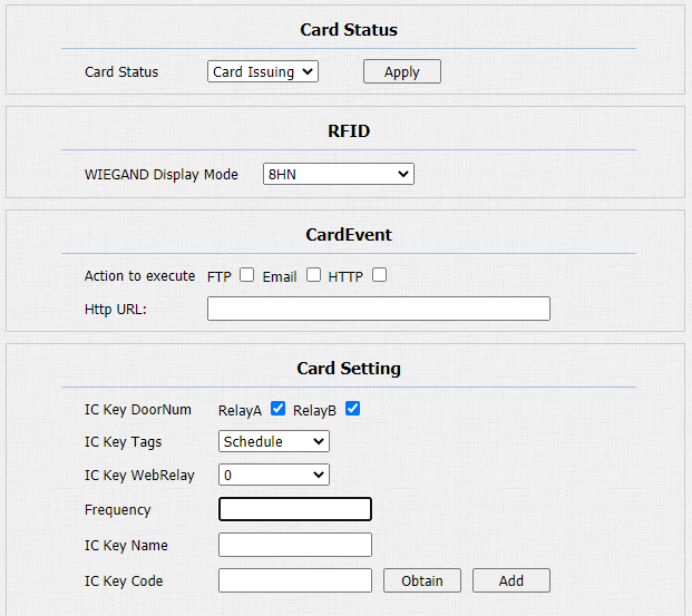
You can go to Access Control > Card Setting > RFID where you can add set up RF card and assign the specific card with a RF card validity schedule for the door access.
Parameter Set-up:
- Card Status: select “Car Issuing” in the field before adding the RFID card and change the status back to “Normal” after the card is added.
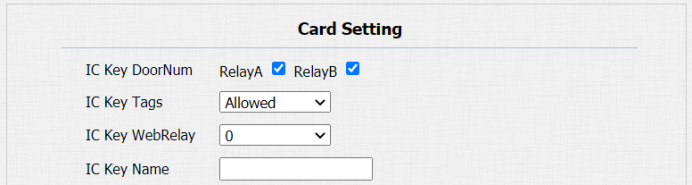
- IC Key DoorNum: select the relay(s) to which the RFID card is applied to.
- IC Key Tags: Select the frequency of the validity the RFID card for the door access among three options: “Allow” “Schedule” and “Forbidden” For example, if you select “Allowed” then the card is always valid for unlimited door access according to your setting. If you select “Schedule” you are required to set up the number of the RFID card access validity. If you select “Forbidden” then the RFID card will never be valid for door access.
- IC Key WebRelay: enter the web relay action ID so that the web relay can be triggered using RFID card for door access. When 0 is selected, then the web relay will not be triggered and it will trigger the built-in relay instead.
- Frequency: set up the number of the RFID card access validity. The maximum number of RF access validity is 65535.
- IC Key Name: enter the RFID card name.
- IC Key Code: RFID card number will appear when the card has been added successfully. You can add 50,000 card maximum.
Note:
- RF card with 13.56 MHz and 125 KHz can be applicable to the access controller for the door access.
After the RF is added, you can assign the RF card with a card validity schedule. You can go to Access Control> Card Setting > Schedule Management for the validity schedule assignment.

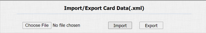
- Import/Export Card data of access control
A092 access controllers support card data of access control to be shared among Akuvox access controllers through import and export while you can also export the card data out of the access controller and then import to a third party device. You can go to Access Control> Card Setting > Import/Export Card Data(.xml) on the web interface.
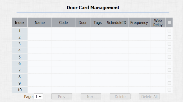
7.3. Edit/Delete Access card Control schedule
After the RFID card is assigned with an access control schedule, you can edit or delete the schedule if needed. You can go to Access Control > Card Setting Door Card Management to select the specific schedule and go to Cart Setting on the same page.

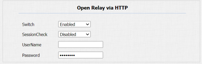
7.4. Configure open relay via HTTP for door unlock
You can unlock the door remotely without approaching the device physically for the door access by typing in the created the HTTP command (URL) on the web browser to trigger the relay when you are not available by the door for the door access. You can go to Access Control > Relay > Open Relay via HTTP for the setting.
Parameter Set-up:
- Switch: enable the HTTP command unlock function by clicking on Enable field. It is enabled by default.
- SessionCheck: enable it so that the door can be unlocked via HTTP command even if the device web interface is not logged in successfully. When it is disabled, door cannot be unlocked via HTTP command.
- User Name: enter the user's name of the device web interface for authentication purpose, for example, “Admin”.
- Password: enter the password for the HTTP command for authentication purpose. For example: “12345”.
Please refer to the following example:
http://192.168.35.127/fcgi/do?action=OpenDoor&UserName=admin&Password=12345&DoorNum=1
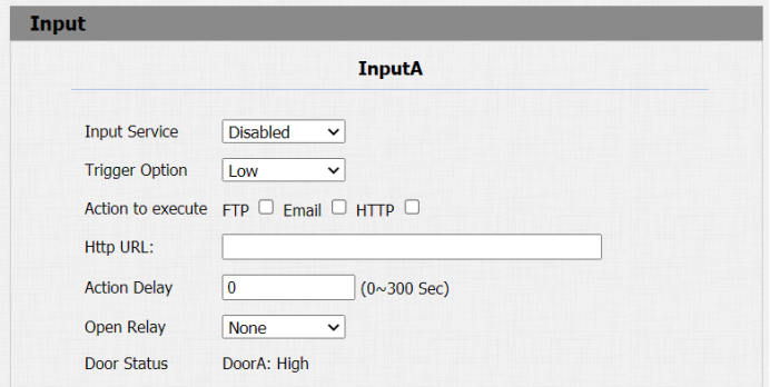
7.5. Configure Exit Button for Door Unlock
When you need to open the door from inside using the Exit button installed by the door, you can configure the access controller Input to trigger the relay for the door access on web interface: Access Control > Input.
Parameter set-up:
- Input service: select "Enable" to be able to use the Input function. It is disabled by default.
- Trigger Option: select the trigger options according to the actual operation on the exit button. It is low by default.
- Action To Execute: select the method to carry out the action among four options: FTP, Email, HTTP, and TFTP.
- HTTP URL: enter the URL if you select the HTTP to carry out the action.
- Action Delay: set up the delay time when the action is carried out. For example, if you set the action delay time at 5 seconds, then the corresponding actions will be carried out 5 seconds after your press the button.
- Open Relay: set up relays to be triggered by the input. It is None by default
- Door Status: display the status of the input signal. It is High by default.
8. Security
Tamper alarm function serves as a protection against any unauthorized removal of the devices by triggering off the temper alarm on the device. You can go to Security > Basic > Tamper Alarm for the setting.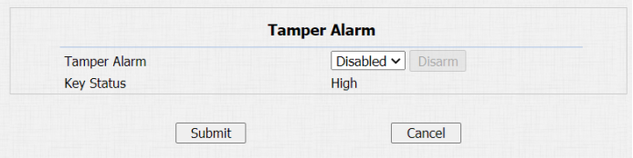
Parameter Set-up:
- Enable: tick the check box to enable the temper alarm function. When the temper alarm goes off, you can press the Disarm tab beside the check box to clear the alarm.
- Key Status: temper alarm will not be triggered unless the key status is shifted from “Low” to “ High” status. The normal status is low.
Note:
- Disarm tab will turn gray when the temper alarm is cleared.
8.1. Security Notification Setting
8.1.1. Email Notification Setting
If you want to receive the security notification via email after door unlock, you can configure the Email notification on the web interface: Setting > Action > Email Notification. The email notification contains the captured images.
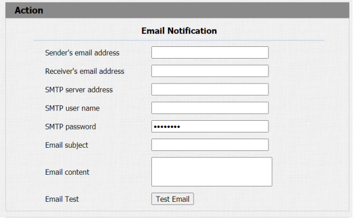
Parameter Set-up:
- Sender's email address: enter the sender’s email address from which the email notification will be sent out.
- Receiver's Email Address: enter the receiver’s email address.
- SMTP Server Address: enter the SMTP server address of the sender. For example: smtps:// smtp.gmail.com
- SMTP User Name: enter the SMTP user name, which is usually the same with sender’s email address.
- SMTP Password: configure the password of SMTP service, which is same with sender’s email address.
- Email Subject: enter the subject of the email.
- Email Content: compile the emails contents according to your need
- Email Test: click on Test email to check if the information are correct.
8.1.2.FTP Notification Setting
If you want to receive the security notification via FTP, you can configure the FTP notification on the web interface: Setting > Action > FTP Notification
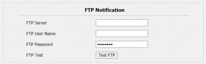
Parameter Set-up:
- FTP Server: enter the address (URL) of the FTP server for the FTP notification.
- FTP User Name: enter the FTP server user name.
- FTP Password: enter the FTP server password.
- FTP Path: enter the folder name you created in FTP server.
9. Door Log
If you want to check door logs and import and export the various types of door access history, you can go to web Access Control > Door Log/Import/Export Door Log(.xml).
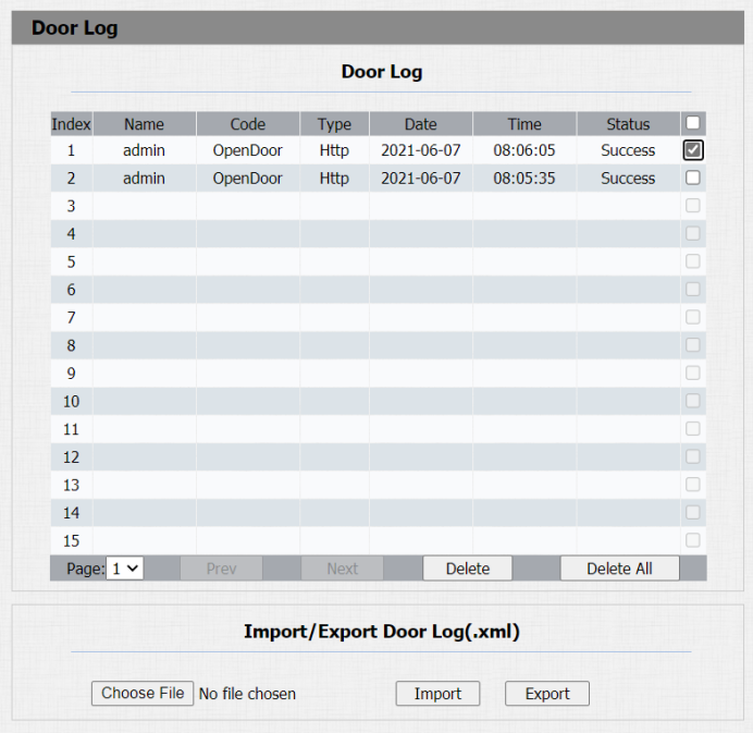
Parameter Set-up:
- Name: displays the card name of the RF card used for the door unlock. It the door in unlocked by unknown cards, then the card name will not be displayed as unknown.
- Code: codes include three types of door access. If the door is unlocked by a card, then the card number will be displayed. If the door is unlocked by Exit button, then it will be display low or high depending on voltage level applied. If the door is unlocked by the HTTP command, then the open-door action will be displayed.
- Type: displays card, HTTP and Input depending on what method is used for the door unlock
- Date: display the door unlock date.
- Time: displays the door unlock time.
- Status: displays door unlock result.
- Choose File: choose the log file from your local PC.
- Import: imported the log file you selected.
- Export: export the existing log file to your local PC.
10. Debug
10.1. Configure Debug Server
If you want to obtain the log for debugging purpose, you can enable the remote debug to collect logs from the device. To set up the debug sever, you can go to Upgrade > Advanced > Remote Debug Server.
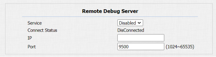
Parameter Set-up:
- Service: enable or disable the remote debug server according to your need. It is disabled by default.
- Connect Status: displays the remote debug server connection status.
- IP: fill in the remote debug server IP address.
- Port: fill in the remoter debug server port (1024-65535). The Akuvox test remote debug server port is 9500. leave the field blank by default.
10.2. System Log for Debugging
System log in A092 access controller can be used for debugging purpose. If you want to export the system out to a local PC or to a remote server for debugging. To configure system log, you can go to
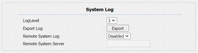
Parameter Set-up:
- LogLevel: select log levels from 1 to 7 levels. You will be instructed by Akuvox technical staff about the specific log level to be entered for debugging purpose. The default log level is “3”. the higher the level is, the more complete the log is.
- Export Log: click the Export tab to export temporary debug log file to a local PC.
- Remote System Server: enter the remote server address to receive the device log. And the remote server address will be provided by Akuvox technical support.
10.3. PCAP for Debugging
PCAP is used to capture the data package going in and out of the devices for debugging and troubleshooting purpose. To set up the PCAP, you can go to
Upgrade > Advanced > PCAP.
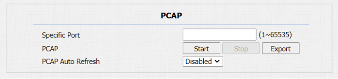
Parameter Set-up:
- Specific Port: select the specific ports from 1-65535 so that only the data packet from the specific port can be captured. You can leave the field blank by default.
- PCAP: click Start tab and Stop tab to capture a certain range of data packets before clicking Export tab to export the data packets to your Local PC.
- PCAP Auto Refresh: select “Enable” or “ Disable” to turn on or turn off the PCAP auto fresh function. If you set it as “Enable” then the PCAP will continue to capture data packet even after the data packets reached its 1M maximum in capacity. If you set it as “ Disable” the PCAP will stop data packet capturing when the data packet captured reached the maximum capturing capacity of 1MB.
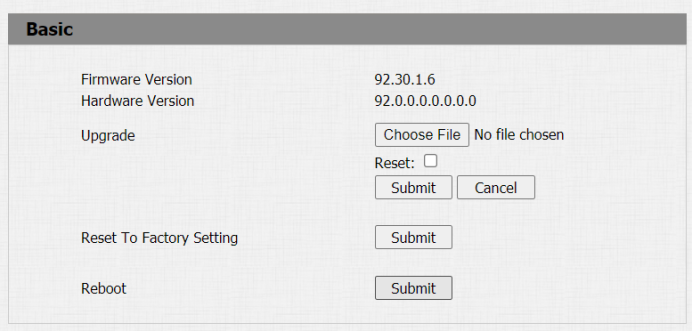
11. Firmware Upgrade
Firmware for A092 access controller can be upgraded on the device web interface, you can go to Upgrade > Basic to upgrade the firmware.
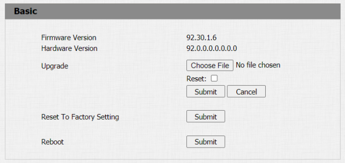
Parameter Set-up:
- Upgrade: Choose .rom firmware from your PC, then click Submit to update.
12. Backup
Configuration files can be imported to or exported out of the device to your local PC. To do so, you can go to Upgrade > Advanced > Others interface if needed.
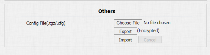
Parameter Set-up:
- Choose File: choose the configuration file to be imported from your Local PC.
- Import: import the new configuration file to the device.
- Export: export the encrypted existing config file from your device to your PC.
13. Auto-Provisioning via configuration File
Configurations and upgrading on A092 access controller can be done on the web interface via one-time auto-provisioning and scheduled auto- provisioning via configuration files, thus saving you from setting up configuration needed one by one manually on the access controller.
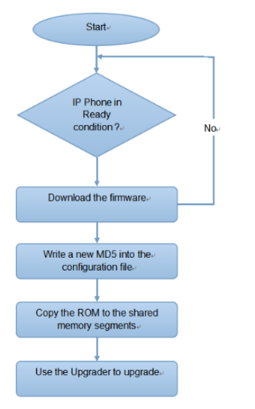
13.1. Provisioning Principle
Auto-provisioning is a feature used to configure or upgrade the devices in batch via third party servers. DHCP, PNP, TFTP, FTP, HTTPS are the protocols used by the Akuvox intercom devices to access the URL of the address of the third-party server which stores configuration files and firmwares, which will then be used to update the firmware and the corresponding parameters on the access controller.
13.2. Configuration Files for Auto-provisioning
Configuration files have two formats for the auto-provisioning. one is the general configuration files used for the general provisioning and other one is the MAC-based configuration provisioning.
The difference between the two types of configuration files is shown as below:
- General configuration provisioning: a general file is stored in a server from which all the related devices will be able to download the same configuration file to update parameters on the devices. For example: r000000000092.cfg.
- MAC-based configuration provisioning: MAC-based configuration files is used for the auto-provisioning on a specific device as distinguished by its unique MAC number. And the configuration files named with device MAC number will be matched automatically with the device MAC number before being downloaded for the provisioning on the specific device.
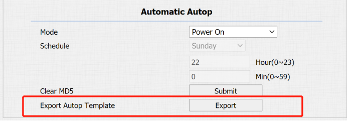
To get the Autop configuration file template, you can go to Upgrade > Advanced > Automatic Autop on the web interface.
Note:
- If a server has these two types of configuration files, then IP devices will first access the general configuration files before accessing the MAC-based configuration files.
13.3. AutoP Schedule
Akuvox provides you with different Autop methods that enable the access controller to perform provisioning for itself in a specific time according to your schedule. You can go to Upgrade > Advanced > Automatic Autop for the setting.
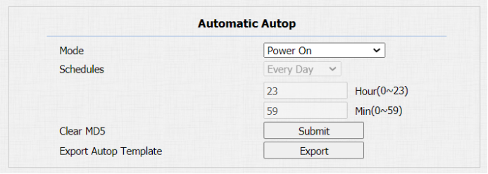
Parameter Set-up:
- Power On: select “Power on”, if you want the device to perform Autop every time it boots up.
- Repeatedly: select “ Repeatedly”, if you want the device to perform autop according to the schedule you set up.
- Power On + Repeatedly: select “Power On + Repeatedly” if you want to combine Power On Mode and Repeatedly mode that will enable the device to perform Autop every time it boots up or according to the schedule you set up.
- Hourly Repeat: select “Hourly Repeat” if you want the device to perform Autop every hour.
13.4. Static Provisioning Configuration
You can manually set up a specific server URL for downloading the firmware or configuration file. If an autop schedule is set up, the access controller will perform the auto provisioning on a specific timing according to Autop schedule you set up. In addition, TFTP, FTP, HTTP, and HTTPS are the protocols that can be used for upgrading the device firmware and configuration.

Parameter set-up:
- URL: set up tftp,http,https,ftp server address for the provisioning
- User Name: set up a user name if the server needs a user name to be accessed to otherwise leave it blank.
- Password: set up a password if the server needs a password to be accessed to otherwise leave it blank.
- Common AES Key: set up AES code for the intercom to decipher general Auto Provisioning configuration file.
- AES Key (MAC): set up AES code for the intercom to decipher the MAC-based auto provisioning configuration file.
Note:
- AES is one type of encryption, it should be configured only when the config file is encrypted with AES, otherwise leave the field blank.
Note:
Server Address format:
- TFTP: tftp://192.168.0.19/
- FTP: ftp://192.168.0.19/ (allows anonymous login)
- ftp://username:password@192.168.0.19/(requires a user name and password)
- HTTP: http://192.168.0.19/ (use the default port 80)
- http://192.168.0.19:8080/ (use other ports, such as 8080)
- HTTPS: https://192.168.0.19/ (use the default port 443)
- Akuvox do not provide users specified server.
- Please prepare TFTP/FTP/HTTP/HTTPS server by yourself.
14. Integration with Third Party Device
14.1. Integration via Wiegand
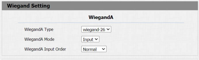
A092 access controller can be connected with the third-party card readers and door strike etc. via Wiegand for the door access control. You can go to Device > Wiegand A/B/C/D for the Wiegand setting on the web interface.
Parameter set-up:
- Wiegand Type: set the wiegand data transmission format among three options: “ Wiegand 26”, “ Wiegand 34”, “ Wiegand 58”. The transmission format should be identical between the access controller and the device to be integrated.
- Wiegand Mode: A092 does not have a built-in card reader module as it only receives the input data from the card reader, therefore the Wiegand mode is invariably Input.
- Wiegand Input Order: select between Normal and Reversed. The card number sequence will be in reversed order if you select Reversed.
14.2. Integration via RS485
RS485 allows you to connect A092 access controller with the third-party devices such as lift controller etc. to achieve the lift control. You can go to Device > RS485 > RS485 List for the setting.

Parameter Set-up:
- None: If you select “None” then the RS485 integration will be disabled.
- OSDP: If you Select “ OSDP” Mode, then the integration communication between the A092 access controller and the third-party device will be via OSDP protocol. You are required to check for the device integration protocol and make sure if that they use the same integration protocol.
14.3. Configure HTTP API for the Third-party Integration
HTTP API is designed to achieve a network-based integration between the third-party device with the A092 access controller. You can go to Security> HTTP API for the setting.
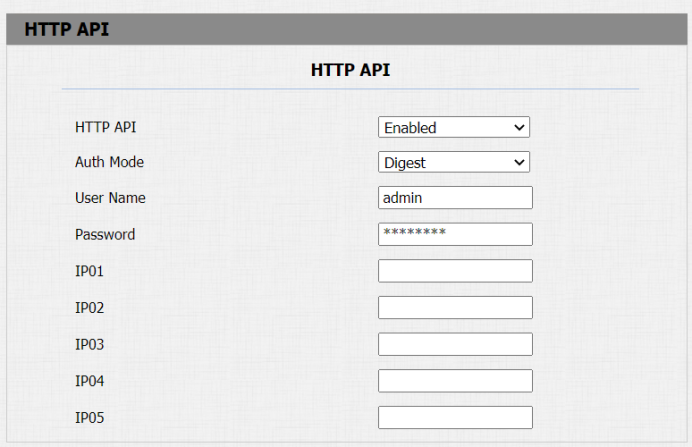
Parameter set-up:
- HTTP API: select “Enable” or “ Disable “ to enable or disable the HTTP API function for the third party integration. For example, if the function is disabled any request to initiate the integration will be denied and be returned HTTP 403 forbidden status.
- Auth Mode: select among four options: “None” “ WhiteList” “ Basic”, “ Digest” for authorization type, which will be explained in detail in the following chart.
- User Name: enter the user's name when “Basic” and “Digest” authorization mode is selected. The default user name is “Admin”.
- Password: enter the password when “Basic” and “Digest” authorization mode is selected. The default user name is “Admin”.
- IP01-IP05: enter the IP address of the third-party devices when the “WhiteList” authorization is select for the integration.
Please refer to the following description for the Authentication mode
NO. | Authorization Mode | Description |
1 | None | No authentication is required for HTTP API as it is only used for demo testing. |
2 | Normal | This mode is used by Akuvox developer only. |
3 | WhiteList | If this mode is selected, you are only required to fill in the IP address of the third-party device for the authentication. The whitelist is suitable for operation in the LAN. |
4 | Basic | If this mode is selected, you are required to fill in the User name and the password for the authentication.In Authorization field of HTTP request header, use Base64 encode method to encode of username and password. |
5 | Digest | Password encryption method, only supports MD5. MD5(Message-Digest Algorithm) In Authorization field of Http request header: WWW-Authenticate:Digest realm="HTTPAPI",qop="auth,auth-int",nonce="xx", opaque="xx". |
6 | Token | This mode is used by Akuvox developer only |
14.4. Power Output Control
A092 access controller can also serve as a power supply for the third-party devices such as card reader and door strike etc. To set up power output, you can go to Access Control > Relay >12V Power Output.
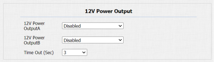
Parameter Set-up:
- 12V Power Output: select Disabled to disable the power output function; select Always to enable the access controller to provide continuous power to the third-party device. Select Triggered By Open Relay if you want the access controller to provide power to the third-party device via 12 output and GND interface during the timeout when the relays status is shifted from low to high.
- Time Out (Sec): select the power supply time duration after the relay is triggered. Three options: 3, 5, 10. It is 3 seconds by default. The power output is 12V. And the maximum output amperage is 0.8A
15. Account &Password
You change the passwords for both Administrator account and User account, as well as change the user account status. You can on the web interface: Security>Basic Web Password Modify/Account Status.
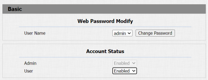
Parameter Set-up:
- User Name: select the Admin if want to change the administrator account password.
- Change password: click on it to change the password.
- Admin: it is enabled by default and is not modifiable
- User: enable or disable the user account according to your need. When
the user account is disable, it will invalidate the user account.
16. System Reboot&Reset
16.1. Reboot
A092 access controller can be rebooted manually or with a reboot schedule on the web interface.
- To reboot the system manually
You can go to Upgrade> Basic for the reboot

- To set up the device reboot schedule
You can go to Upgrade > Advanced > Reboot Schedule for the reboot.
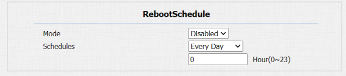
Parameter Set-up:
- Mode: enable or disable the reboot schedule according to your need.
- Schedule: select the time schedule for the reboot.
16.2. Reset
If you want to reset the device system to the factory setting, you can go to Upgrade > Basic on the web interface.
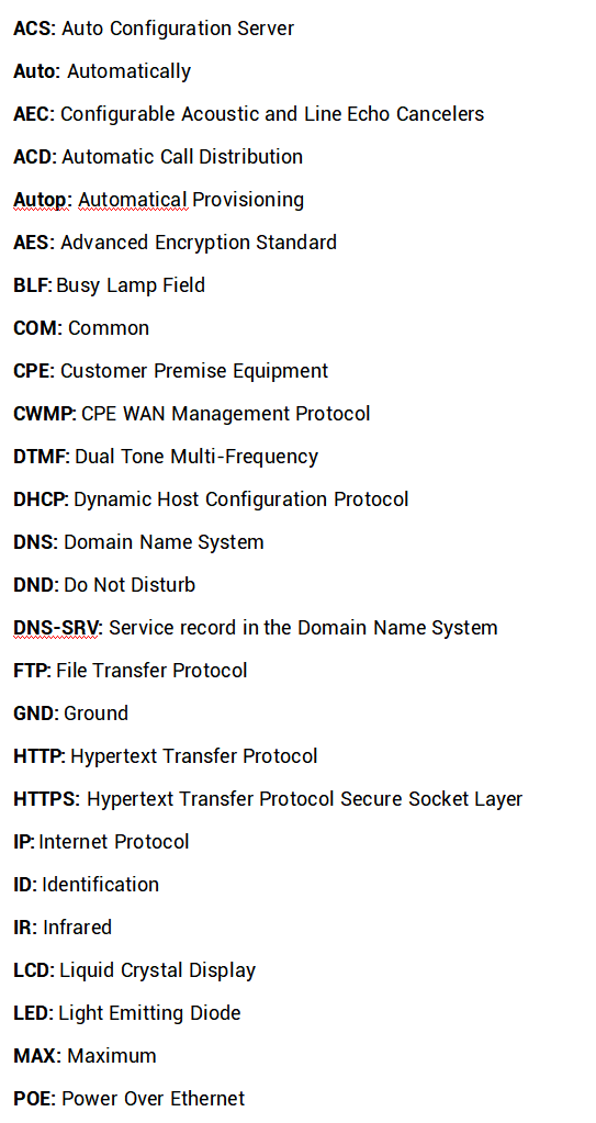
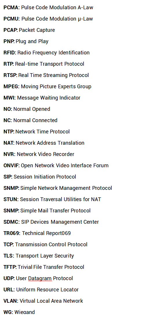
17. Abbreviations
18. FAQ
Q1: How to obtain IP address of R2X
A1: ✔ For devices with single button - E21/ R20/ R23/ R26:
While E21/ R20/ R23/ R26 power up normally, hold the call button for 5 seconds after the statue LED turns blue and it will enter into IP announcement mode. In announcement mode, the IP address will be announced repeatedly. Press call button again to quit the announcement mode.
✔ For devices with multiple numeric keyboard - R27:
While R27 power up normally, press “*2396#” to enter home screen and press “1” to go to system Information screen to check the IP address.
✔ For devices with touch screen - X915:
While X915 power up normally, in the dial interface, press “9999“, “Dial key”, “3888” and “OK” to enter the system setting screen. Go to info screen to check the IP address.
✔Common method:
Using Akuvox IP Scanner to search Akuvox devices in the same LAN network.
Q2: Do Akuvox devices support opus codec?
A2: For now, only Akuvox Android video IP phone R48G can support Opus audio codec.
Q3: What is the supported temperature range for akuvox doorphone?
A3: R20/E21/R26/R23/Standard R27/Standard X915 -- 14° to 112°F (-10° to 45°C)
R27/X915 with heating supporting --- 40 degrees
R28 -- (-40°C~55°C)
Indoorphone -- 14° to 112°F (-10° to 45°C)
IPPhone -- 32º~104ºF(0~40ºC)
Q4: Do Akuvox devices support Modbus protocol?
A4: No.
Q5:Failure in importing the X915 face data to another X915 using the exported face data.
A5:Please confirm the following steps:
The import format is zip;
- After you export, you need to unzip the .tgz folder, then make the unzipped folder into .zip again.
Q55: Which version of ONVIF does R20 and X915 support?
A55: Onvif 18.04 profiles
Q6: Do access controllers support these card types? Prox, Legacy iClass,iClassSE,HID Mifare, HID DESFire,HID SEOS
A6: Sorry, they are not supported. They need to be implemented via hardware modifications.
Q7: How to confirm whether my device is hardware version 1 or hardware version 2?
A7: 1. Label
- Hardware version 1
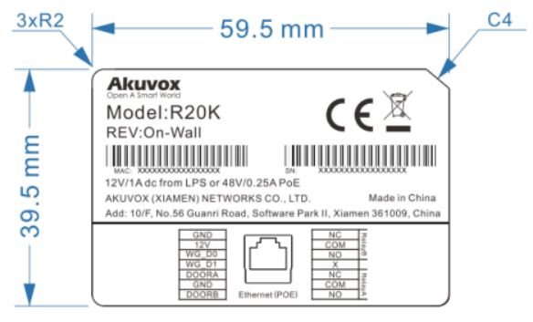
- Hardware version 2
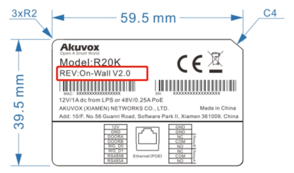
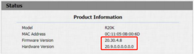
- Firmware Version
The firmware is different between hardware version1 and hardware version 2.
Go to Web-Status -Firmware Version.
20.X.X.X is hardware version 1.
220.X.X.X is hardware version 2.
- Hardware version
The firmware is different between hardware version1 and hardware version 2.
Go to Web-Status -Firmware Version.
If the hardware version is 220.x, then the device is hardware version 2.
19. Contact us
For more information about the product, please visit us atwww.akuvox.com or feel free to contact us by
Sales email: sales@akuvox.com
Technical support email: support@akuvox.com
Telephone: +86-592-2133061 ext.7694/8162
We highly appreciate your feedback about our products.