Integration via Wiegand
The device can be integrated with third-party devices via Wiegand.
Set it up on the Device > Wiegand interface.
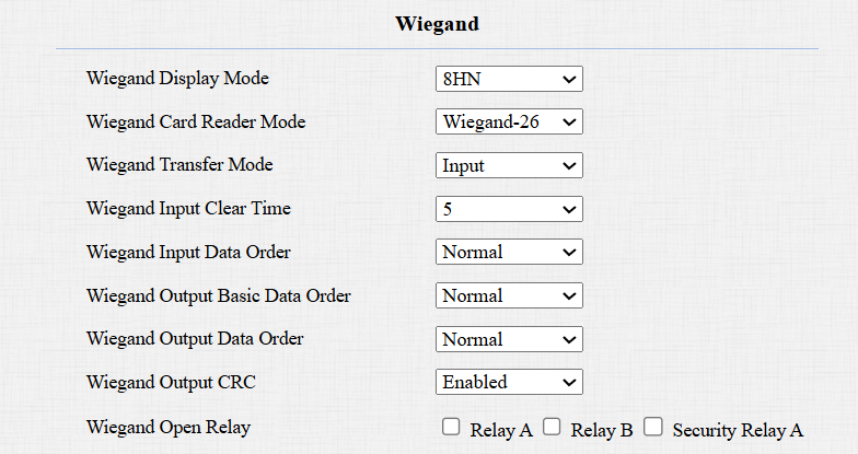
Wiegand Display Mode: Select the Wiegand card code format from the provided options.
Ignore Facility Code: This option is available when 6H3D5D(WG26) is selected. When enabled, the first three bits of the cards will be ignored for successful card reading.
Wiegand Card Reader Mode: The transmission format should be identical between the door phone and the third-party device. You can customize the card reader mode by selecting Customize, then further set up the following options:
Note
The Customize function ONLY works for Input Wiegand Transfer Mode.
Wiegand Display Mode:
HEX(Hexadecimal): The default option. Base-16 numbering system that uses digits from 0 to 9 and letters from A to F.
DEC(Decimal): The base-10 numbering system that uses digits 0-9 only.
Total Number of Bits: Define the bit number of the card data for processing. The range is from 1 to 128. The default is 26.
Card Number Length: Specify the bits used to store the card number, limited by the Total Number of Bits. For example, when the total bit number is 26, you can specify a length between 1 and 26 to be read as a card code.
Use Site Code: Set whether to use the site code. You may need to enable it when the third-party access control system requires the site code for processing the card's information.
When enabled, specify the bits read by the device, limited by the Total Number of Bits. For example, when the total bit number is 26, the range is from 1 to 26.
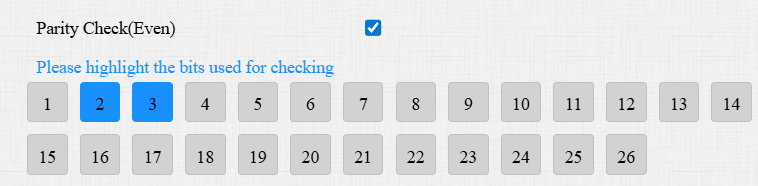
Parity Check(Even): When enabled, the sum of selected bits must be even to pass verification. For example, when the second and third bits are selected and their sum is even, the parity check passes.
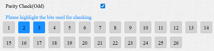
Parity Check(Odd): When enabled, the sum of selected bits must be odd to pass verification. For example, when the second and third bits are selected and their sum is odd, the parity check passes.
Tip
Parity check is a simple error detection mechanism used to ensure that data has not been corrupted during transmission or storage.
When it is enabled, the device will first perform the check. Only if the check passes will it read the card number.
Card Reading Example:
Suppose total number of bits is 32 and the card data is 0011 1000 0101 1100 0010 0100 0011 1110.
Display Mode
Card Number Length
Site Code
Parity Check
Card Code
HEX: 385C243E
13-32 Bits: C243E
1-12 Bits: 385
2-15 bits(Even): The sum is 7, fail to pass the check.
16-31 bits(Odd): The sum is 7, successfully pass the check.
C243E
Wiegand Transfer Mode:
Input: The device serves as a receiver.
Output: The device serves as a sender and can directly output the data, such as a card code.
Convert To Card No. Output: The device serves as a sender and cannot directly output the data.
Wiegand Input Clear Time: When the interval of entering passwords via Wiegand exceeds the time, all entered passwords will be cleared.
Wiegand Input Data Order: Set the Wiegand input data sequence between Normal and Reversed. If you select Reversed, then the input card number will be reversed.
Wiegand Output Basic Data Order: Set the sequence of the card data before going through Wiegand conversion and outputting the card code.
For example, if the card data is 0x11 0x22 0x33 0x44 and the Reversed option is selected, the data will be 0x44 0x33 0x22 0x11.
Wiegand Output Data Order: Determine the sequence of the card data after the Wiegand conversion.
For example, if the card data is 0x11 0x22 0x33 0x44 0x55, it will be 0x33 0x44 0x55 after the Wiegand conversion(e.g., Wiegand 26). If Reversed is selected, the card data is 0x55 0x44 0x33.
Wiegand Output CRC: It is enabled by default for Wiegand data inspection. Disabling it may lead to integration failure with third-party devices.
Wiegand Open Relay: Select the relay triggered by Wiegand.
When the door phone is in Wiegand output mode, you can configure the Wiegand PIN code output format that determines how data is transmitted. The format should be the same as that of the third-party device.
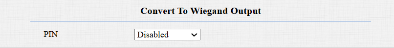
Disabled: Turn off the feature.
8 bits per digit: When users press "1" on the keypad, the binary data will be transmitted in 8 bits, "11100001".
4 bits per digit: When users press "1" on the keypad, the binary data will be transmitted in 4 bits, "0001".
Note
Click here to view more information on Wiegand settings including:
Akuvox devices work as Wiegand input/output;
Wiegand Card Reader Connection.
Facility Code Setting
A facility code is a unique number in access control cards. It identifies the device that issued the card.
When the Wiegand Transfer Mode is Output, you can set up the facility code on the Device > Wiegand interface.
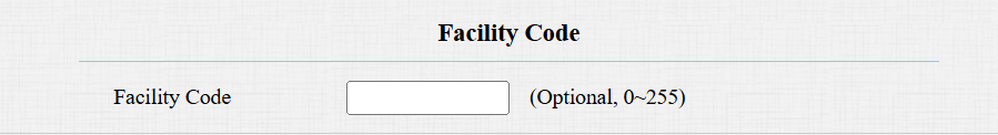
Facility Code: The value ranges from 0 to 255. If filled in, the first two digits of the card number will be replaced by the code. If the code is less than 2 digits, a zero will be automatically added to the card number.
Tip
Since the Facility Code replaces the first two digits of the original card number, to keep the original card number intact, you can manually configure the Wiegand Card Reader Mode.
For example, if the card number is 3 bytes (Wiegand-26), you can select Wiegand-34 (4 bytes) to ensure the Facility Code replaces the first two digits with 0 instead of the original number.
Integration via HTTP API
HTTP API is designed to achieve a network-based integration between the third-party device and the Akuvox device.
Set it up on the web Setting > HTTP API interface.

Enabled: Enable or disable the HTTP API function for third-party integration. If the function is disabled, any request to initiate the integration will be denied and return HTTP 403 forbidden status.
Authorization Mode: See the description for each option in the chart below.
Username: Enter the user name for authentication. The default is admin.
Password: Enter the password for authentication. The default is admin.
1st IP-5th IP: Enter the IP address of the third-party devices when the Allowlist authorization is selected for the integration.
Please refer to the following description for the authentication mode:
NO. | Authorization Mode | Description |
|---|---|---|
1 | None | No authentication is required for HTTP API as it is only used for demo testing. |
2 | Normal | This mode is used by Akuvox developers only. |
3 | Allowlist | If this mode is selected, you are only required to fill in the IP address of the third-party device for the authentication. The whitelist is suitable for operation in the LAN. |
4 | Basic | If this mode is selected, you are required to fill in the User name and the password for the authentication. In the Authorization field of the HTTP request header, use the Base64 encoding method to encode the username and password. |
5 | Digest | The password encryption method only supports MD5(Message-Digest Algorithm). In the Authorization field of the Http request header:WWW-Authenticate: Digest realm="HTTP API", qop="auth,auth-int", nonce="xx", opaque="xx". |
6 | Token | This mode is used by Akuvox developers only. |
Power Output Control
The device can serve as a power supply for the external relays. Click here to view power output requirements.
To set it up, go to the Access Control > Relay > 12V Power Output interface.
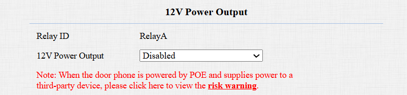
12V Power Output: To supply power for third-party devices, the door phone should be powered by a PoE or DC power connector with input not less than 12V/1.2A.
Disabled: Turn off the function.
Always: Provide continuous power.
Triggered by Open Relay: Provide power to the third-party device when Relay A is triggered via its NO and GND ports. Stop providing the power when Relay A is reset.
Timeout(Sec): Set the time(3, 5, or 10 seconds) to provide power when Triggered by Open Relay is selected.
Note
When the door phone is powered by PoE, its volume adjustment affects power supply.
If the third-party device operates at 12V and ≤0.2A, the door phone supports both Level 1 and 2 volume.
If the device operates at 12V and 0.2A–0.4A, only Level 1 is supported; Level 2 may cause a shutdown.
If the device exceeds 0.4A at 12V, it will shut down due to insufficient power.
Integration via RS485
You can connect the device to an external device such as SR01 or an OSDP-based card reader via RS485. To make the connection effective, you need to select the right RS485 mode.
Click here to view the detailed configuration of the OSDP feature.
To set it up, go to the Device > RS485 interface.
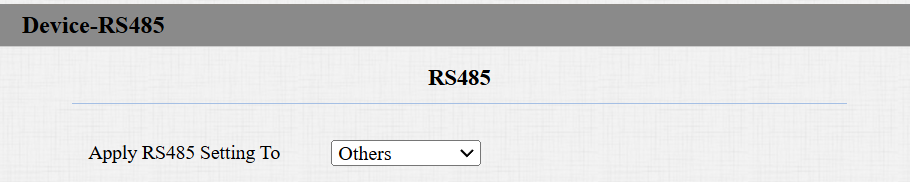
Disabled: The RS485 function is disabled.
OSDP: The device is connected to an OSDP-based external device such as a card reader.
Encryption: Check this option when the protocol is encrypted.
SCBK Value: Secure Communication Key Value.
When it is filled, OSDP will use this value for encryption, employing a customized protocol for communication.
When it is left empty, OSDP will use the default encrypted protocol for communication.
Others: Select this option when the device works with the SR01 or other non-OSDP-based devices.