Integration via Wiegand
The device has 8 readers, which can work in Wiegand or OSDP mode. The Wiegand feature enables the Akuvox device to act as a controller.
To set it up, go to the Device > Reader interface. Set the reader mode to Wiegand.
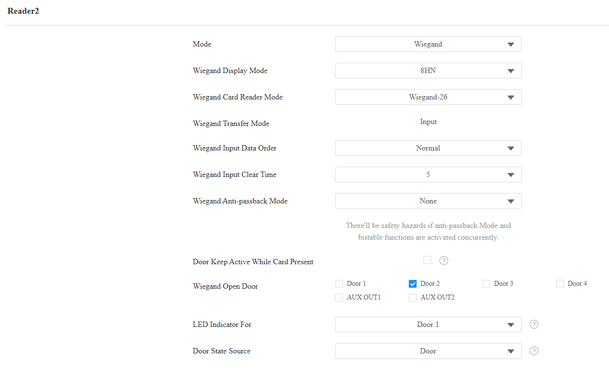
Wiegand Display Mode: Select the Wiegand card code format from the provided options: 8H10D, 6H3D5D(W26), 6H8D, 8HN, 8HR, 6H3D5D-R(W26), 8HR10D, and RAW.
Ignore Facility Code: This option is available when 6H3D5D(WG26) is selected. When enabled, the first three bits of the cards will be ignored for successful card reading.
Wiegand Card Reader Mode: The transmission format should be identical between the access control terminal and the third-party device. It is Wiegand 26 by default.
When Customize is selected, further set up the following options:
Display Mode:
HEX(Hexadecimal): The default option. Base-16 numbering system that uses digits from 0 to 9 and letters from A to F.
DEC(Decimal): The base-10 numbering system that uses digits 0-9 only.
Total Number of Bits: Define the bit number of the card data for processing. The range is from 1 to 128. The default is 26.
Card Number Length: Specify the bits used to store the card number, limited by the Total Number of Bits. For example, when the total bit number is 26, you can specify a length between 1 and 26 to be read as a card code.
Use Site Code: Set whether to use the site code. You may need to enable it when a third-party access control system requires the site code for processing the card's information.
When enabled, specify the bits read by the device, limited by the Total Number of Bits. For example, when the total bit number is 26, the range is from 1 to 26.
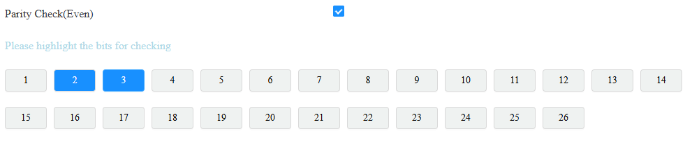
Parity Check(Even): When enabled, the sum of selected bits must be even to pass verification. For example, when the second and third bits are selected and their sum is even, the parity check passes.
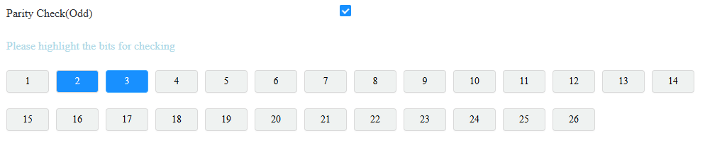
Parity Check(Odd): When enabled, the sum of selected bits must be odd to pass verification. For example, when the second and third bits are selected and their sum is odd, the parity check passes.
Tip
Parity check is a simple error detection mechanism used to ensure that data has not been corrupted during transmission or storage.
When it is enabled, the device will first perform the check. Only if the check passes will it read the card number.
Card Reading Example:
Suppose total number of bits is 32 and the card data is 0011 1000 0101 1100 0010 0100 0011 1110.
Display Mode
Card Number Length
Site Code
Parity Check
Card Code
HEX: 385C243E
13-32 Bits: C243E
1-12 Bits: 385
2-15 bits(Even): The sum is 7, fail to pass the check.
16-31 bits(Odd): The sum is 7, successfully pass the check.
C243E
Wiegand Transfer Mode: It is Input by default. It means the device serves as a receiver, which allows users to open doors by swiping an RF card or entering a PIN code on the third-party card reader.
Wiegand Input Data Order: Set the Wiegand input data sequence between Normal and Reversed. If you select Reversed, then the input card number will be reversed. For example, the card code is 00345678.
Normal: The code is 00345678 displayed on the device’s carding adding interface.
Reversed: The code is 00785634 displayed on the device’s carding adding interface.
Wiegand Input Clear Time: When the interval of entering passwords exceeds the time, all entered passwords will be cleared.
Wiegand Anti-passback Mode: Select from Entry and Exit. This mode restricts users from entering the door by following others. For example, if the user follows someone else through the door, the next time he/she cannot swipe his/her card to pass the Entry/Exit door.
Door Keep Active While Card Present: This feature keeps the relay triggered continuously while a valid card stays within the reader's detection range. The relay will deactivate automatically when the card is moved away.
Note
Upon detecting a valid card, the device generates a Card Present Access Log and activates the relay.
While continuously reading the card, the relay remains active. No additional Access Logs are generated.
Upon detecting the card leaving the reading area, the device generates a Card Removed Access Log.
Wiegand Open Door: Select the door to be opened by Wiegand.
LED Indicator For: Each reader has GLED and RLED interfaces to control the indicator lights of the Wiegand card reader.
If None is selected: GLED and RLED do not show the real-time status of the door. They only indicate whether a door opening action was successful.
If a specific door is selected: GLED and RLED show the real-time status of that door.
When the door is open, GLED stays lit, and RLED turns off.
When the door is locked down, RLED stays lit, and GLED turns off.
Door State Source: Available when LED Indicator For is configured. It determines whether the door's status is defined by Door or by Input(Door Sensor).
Integration via RS485
The device has 8 readers, which can work in Wiegand or OSDP mode.
Set it up on the web Device > RS485 interface. Set reader mode to OSDP.
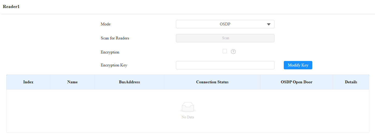
Scan for Readers: Click Scan to detect the connected card reader.
Encryption: Check this option when the OSDP protocol is encrypted.
Encryption Key: Fill in the key when Encryption is checked. Please confirm the key with the card reader service provider.
Modify Key: Click to modify the encryption key, which must be 32 bits long and can include numbers (0-9) and letters (a-f, A-F).
Connection Status: Display whether the reader is online and connected properly.
OSDP Open Door: Check the door to be opened.
Details: Click to view the card reader’s information.
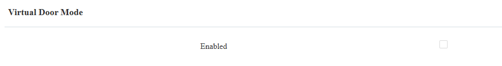
Virtual Door Mode:
It is disabled by default. Users can ONLY open doors that are checked on both the Reader setting and Access Setting interfaces.
If it is enabled, users can open doors that are checked on the Reader setting interface with their credentials, regardless of whether they are checked on the Access Setting interface.
Note
Click here to view the detailed configuration of the OSDP feature.
Integration via HTTP API
HTTP API is designed to achieve a network-based integration between the third-party device and the Akuvox device.
To set it up, go to Setting > HTTP API interface.
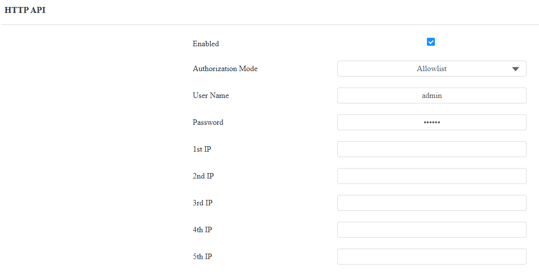
HTTP API Enable: Enable or disable the HTTP API function for third-party integration. If the function is disabled, any request to initiate the integration will be denied and return HTTP 403 forbidden status.
Authorization Mode:
None: No authentication is required for the HTTP API, as it is only used for demo testing.
Normal: This mode is for Akuvox developers only.
Allowlist: This mode requires you to enter the IP addresses of the devices you allow for the integration via HTTP API.
Basic: This mode requires you to fill in the authentication username and password. In the Authorization field of the HTTP request header, use the Base64 encoding method to encode the username and password.
Digest: The password encryption method only supports MD5. MD5( Message-Digest Algorithm) In the Authorization field of HTTP request header: WWW-Authenticate: Digest realm="HTTPAPI",qop="auth,auth-int",nonce="xx", opaque="xx".
Token: This mode is only used by Akuvox developers.
Username: Enter the user name when Basic or Digest authorization mode is selected. The default username is admin.
Password: Enter the password when Basic or Digest authorization mode is selected. The default password is admin.
1st IP-5th IP: Enter the IP address of the third-party devices when the Allowlist authorization is selected for the integration.
Power Output Control
The device can serve as a power supply for the external relays. Click here to view power output requirements.
To set it up, navigate to the web Access Control > Door interface.
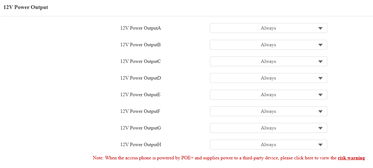
12V Power Output ID: Specify the output(4 Door interfaces and 4 AUX OUT interfaces) for supplying power.
Power Output Type: Select the power output type.
Always: The device will provide a continuous power supply. The device's door status will be changed from NC to NO status after the door interface is triggered, thus cutting off the power. The power supply will be resumed after the door is reset.
Triggered by Open Door: It is generally for the GND and NO connection.
After triggering, the door status switches from NO to NC, initiating the power supply.
The power supply is cut off after the door interface is reset.
The door interface can be reset automatically after the pre-selected timeout(3, 5, or 10 seconds).
Time Out(Sec): This option is available when Triggered by Open Door is selected. Set the door interface reset time.
Note
Powered by PoE+, A095 provides 12V power with a maximum per-port current of 0.2A if the device’s READER interfaces are connected fully to 8 devices. It provides 12V power with the per-port current between 0.2A and 0.4A if the device’s READER interfaces are connected to 4 devices or fewer.
Powered by a 12V/5A DC power connector, A095 provides 12V/500mA per port.