1. Function Overview
The K32 button panel supports tactile control and integrates features such as RGB/RGBW color adjustment and color temperature control. It also includes a built-in temperature sensor to detect ambient room temperature, covering most daily use cases.
Each button can be individually configured to support various functions, including switching, dimming, curtain control, scene activation, value transmission, shift register, multi-action, and delay modes.
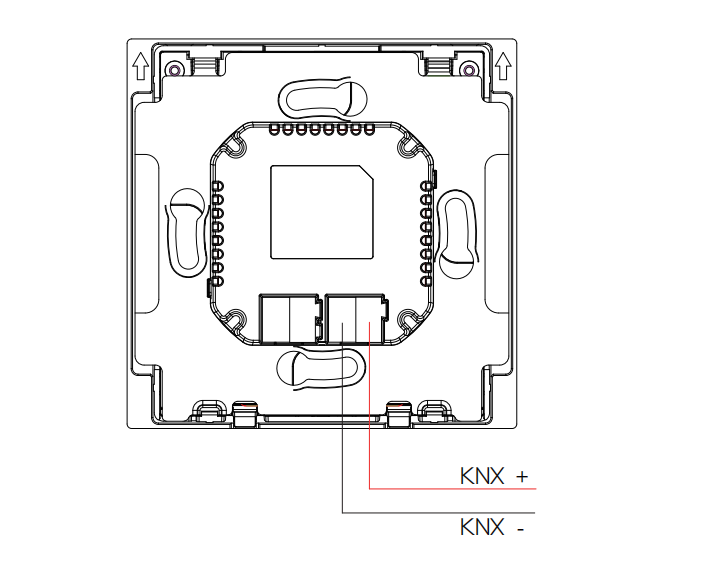
The K32 panel is powered via the red and black KNX bus terminals only. Physical address assignment and parameter configuration are performed using ETS (Engineering Tool Software) version 5.7 or higher, with the corresponding .knxprod file.
Key Features:
Basic control functions including switch, dimming, curtain, scene, value sending, shift register, multi-operation, delay mode
Scene group and logic functions
Built-in proximity sensor
Integrated temperature sensor
Buttons with RGB indicator lights, can act as standard key panel
Support KNX Secure
2. Technical Parameters
Category | Item | Specification |
Electrical | KNX Power Supply | 21–30 V DC |
Rated current: 12mA@21V | ||
Rated Power | 360 mW | |
Appearance | Material | Metal, V0 fireproof |
Indicator Screen | 0.87-inch OLED | |
Sensors | Proximity Sensor | 30–100 cm |
Temperature Sensor | ±0.5℃ range: -10℃–50℃ | |
Humidity Sensor | ±1%, range: 10%–90% RH (non-condensing) | |
Working Environment | Environment | Indoor Use Only |
Working Humidity | 10%–90% RH (non-condensing) | |
Working Temperature | -10℃–50℃ | |
Storage Temperature | -20℃–70℃ | |
IP Rating | IP20 |
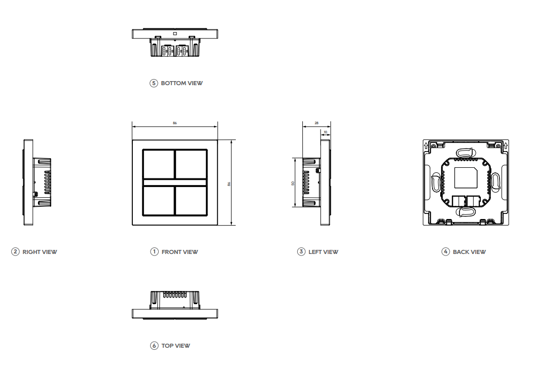
3. Product Dimensions and Wiring Diagram
Product Dimensions
Unit: mm
Wiring Diagram
4. Project Design and Application
Application program | Max. number of communication objects | Max. number of group addresses | Max. number of secure group addresses | Max. number of association tables |
K32 Button Panel | 217 | 1000 | 1000 | 1000 |
Function Description
General setting
This section provides configuration options for button LED brightness, OLED display behavior, and proximity sensing. Temperature sensor calibration is also supported, allowing for more accurate environmental data reporting and enabling interlocking with other devices.
Button control
Each button can be independently enabled or disabled and assigned specific control functions. When linked to touch operations, buttons can be preset to control targeted devices.
The device supports standalone panel use with the following standard KNX control functions: switching, dimming, curtain control, scene triggering, value transmission, shift register, multi-operation commands, and delayed modes.
For switching, scene, and value transmission functions, short press and long press actions can be assigned to either a shared object or two separate ones.
LED Indicators
The indicator light brightness is adjustable and can change automatically based on day or night conditions. The display and indicator lights turn off after a configured delay and light up simultaneously when the device is awakened.
Logic function
Support up to 8 logic channels, each with up to 8 inputs and one output.
Available logic operations include AND, OR, XOR, gate conversion, threshold comparison, format conversion, and logic gate processing.
Event group
Calling a scene number can trigger 8 output telegrams, each configurable with one of three data types. A total of 8 event groups are available for configuration.
Security feature
Security features can be enabled, with downloads performed via FDSK and the project protected by a password. If the password is forgotten, press and hold the programming button on the base for 5 seconds to restore factory settings. After resetting, the project must be downloaded again using FDSK.
5. ETS Parameter Settings
5.1 Overview
The K32 KNX button panel offers flexible parameter settings to support various application scenarios.
5.2 Parameter setting interface “General Setting”
5.2.1 “General setting”
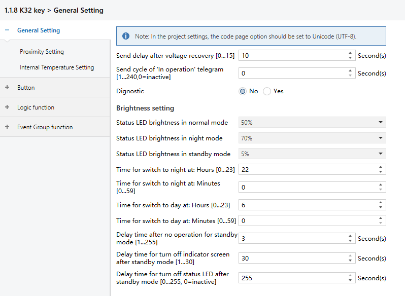
Figure 5.2.1: General setting interface
Send delay after voltage recovery [0..15]s
Set the delay time before the device sends telegrams to the bus after power-on reset.
Options: 0~15
NOTE:
This delay does not include the device initialization time. Telegrams received during this period are still recorded.
Send cycle of “In operation ” telegram [1...240s, 0 = inactive]
Set the time interval when this device cycle send telegrams through the bus to indicate this module in normal operation.
When set to “0”, the object “In operation” will not send a telegram.
If the value is not “0”, the object “In operation” will send a telegram with a logic “1” to the bus at the preset time interval.
Options: 0~240s, 0 = inactive
To minimize the bus load as much as possible, the maximum time interval should be selected according to actual needs.
Status LED brightness in normal mode
Set the button’s LED brightness level during the day.
Options:
0%
5%
10%
20%
...
70%
Status LED brightness in night mode
Set the button’s LED brightness level during nighttime.
Options:
0%
5%
10%
20%
...
70%
Status LED brightness in standby mode
Set the button’s LED brightness level when the device enters standby mode.
Options:
0%
5%
10%
20%
...
70%
Time for switch to night at: Hours [0...23]
Set the hour the hour when night mode begins.
Options: 0~23
Time for switch to night at: Minutes
Set the minute when night mode begins.
Options: 0~59
Time for switch to day at: Hours [0...23]
Set the hour when day mode begins.
Options: 0~23
Time for switch to day at: Minutes
Set the minute when day mode begins.
Options: 0~59
Delay time after no operation for standby mode
Set the time of inactivity before the panel enters standby mode.
Options: 1~255
Delay time for turn off indicator screen after standby mode
Set how long the OLED screen remains on after entering standby mode.
Options: 1~30
Delay time for turn off status LED after standby mode
Set how long the LED indicators remain on after entering standby mode.
When the value is “0”, the LEDs remain on permanently.
Options: 0~255, 0=inactive
5.2.2 “Proximity setting”
The Proximity Setting interface, as shown in Figure 5.2.2, configures the proximity sensing feature, including sensor source, detection distance, the telegrams sent when a person approaches or leaves the sensing area, along with the delay time for sending these telegrams. “Approaching” means the built-in sensor detects someone entering the area, and “Leaving” means no presence is detected.
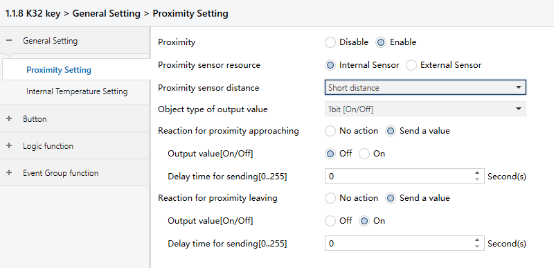
Figure 5.2.2: Proximity setting interface
Proximity
Enable or disable the proximity sensing feature.
Options:
Disable: Turn off proximity sensing, hiding the “Proximity sensor resource” setting.
Enable: Activates proximity sensing. The panel will automatically wake based on the selected sensor source.
Proximity sensor resource
This setting appears when proximity sensing is enabled and allows you to select the sensor source.
Options:
Internal Sensor: Use the panel’s built-in sensor. When selected, the “Proximity sensor resource” and “Object type of output value” settings are shown.
External sensor: Uses an external sensor. When selected, the “Proximity sensor resource” and “Object type of output value” settings are hidden.
Proximity sensor distance
This setting appears only when the Internal Sensor is selected. It sets the detection range of the built-in sensor.
Options:
Short distance: Detect presence within 30cm to wake the screen.
Medium distance: Detect presence within 60cm to wake the screen.
Long distance: Detect presence within 100cm to wake the screen.
Object type of output value
This setting appears when “Internal Sensor” is selected as the proximity sensor source. This sets the data type of telegrams sent to the bus when a person approaches or leaves the sensing area.
Options:
1bit[On/Off]
1byte[scene control]
1byte[0..255]
1byte[0.100%]
Reaction for approaching/leaving
Set whether to send telegrams when a person approaches or leaves the sensing area.
Options:
No action
Send a value: Enables the following settings for telegram values sent on approach or leave. Note that the available value ranges depend on the selected data type.
Output value[On/Off]
Output scene NO.[1..64]
Output [0..255]
Output value[0..100%]
Delay time for sending[0..255]
Set the the delay before sending telegrams.
Options: 0~255
NOTE:
When the K32 detects an approaching object, it delays sending the “leaving” telegram based on the time set in “General Setting-Delay time after no operation for standby mode”. If the radar is triggered again during this delay, the timer resets.
5.2.3 “Internal temperature setting”
The Internal Temperature Setting interface, shown in Figure 5.2.3, allows configuration of parameters related to the internal temperature sensor.
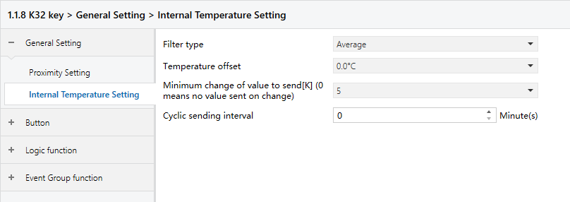
Figure 5.2.3: Internal temperature Setting interface
This section covers the configuration of filter type, calibration (temperature offset), conditions for sending data, and the cyclic sending interval.
Filter type
Specify the number of measured values used to calculate the average before sending it to the bus.
Options:
Low: Average 4 measurements
Average: Average 16 measurements.
High: Average 64 measurements.
Temperature offset
Set the calibration value of the internal temperature sensor to match actual ambient temperature. This only affects the telegram values sent to the bus and does not change the temperature shown on the panel.
Options: -5℃~5℃
Minimum change of value to send[K] (0 means no value sent on change)
Define the minimum temperature change required to trigger sending a telegram of current temperature.
Options: 0~5 (0 = Do not send on change)
Send actual Humi. when change by[1..20]
Set the minimum humidity change needed to trigger a telegram of current humidity.
Options: 1~20
Cyclic sending interval
Specify how often the current temperature value is sent to the bus.
Options: 0~120min
NOTE:
This cycle starts after device programming or reset and runs independently of value-change triggers.
5.3 Parameter setting interface “Button”
5.3.1 “Button”
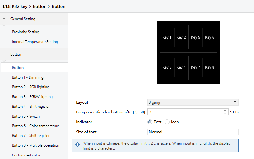
Layout
Set the number of buttons on the K32 panel.
Options:
2 gang: 2 buttons
3 gang: 3 buttons
4 gang: 4 buttons
6 gang: 6 buttons
8 gang: 8 buttons
The system will then generate corresponding thumbnails and text/icon configuration fields based on the selected button count.
Long operation for button after
Set the time threshold for recognizing a long press.
If a button is pressed longer than the set duration, it is treated as a long operation; otherwise, it is treated as a short press.
Indicator
Select how the button label is displayed on the OLED screen.
Options:
Text: Display a text label.
Icon: Display an icon.
The following parameters appear when the “Text” is selected.
- Indicator text x
Set the displayed text, allowing up to 13 characters as input.
NOTE:
The maximum display length depends on the layout and font size settings:
For 2, 3, or 4 gang layouts with Normal size: Up to 4 Chinese characters or 6 letters.
For 2, 3, or 4 gang layouts with Large size: Up to 2 Chinese characters or 5 letters.
For 6 or 8 gang layouts (Normal size only): Up to 2 Chinese characters or 3 letters.
- Size of font
Set the size of the text.
Options:
Normal or Large for 2-4 gang layouts
Normal (default) for 6 and 8 gang layouts
The following parameters appear when the “Icon” is selected.
- Indicator icon x
Select the icon to be displayed.
Options:
Leave home
Dinner
Go home
Shade
AC
Lighting
Music
Sleep
Coffee
Floor heating
Gym, Reading
Scenario
Function of button x
Set the function assigned to the button.
Options:
Disable
Switch
Dimming
RGB lighting
RGBW lighting
colour control type
Value sender
Scene control
Shade
Shift register
Multiple operation
Delay mode
The following sections provide detailed description for each button function.
5.3.2 “Switch”
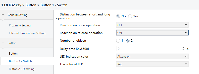
Distinction between short and long operation
Set whether to distinguish between short and long button presses.
Options:
No
Yes: The button differentiates based on the press duration. Only when the press time reaches the defined threshold will it be recognized as short or long, and the corresponding function will be executed.
Reaction on short/press operation
Reaction on long/release operation
Define the action triggered during short or long press and release events. The object value is updated immediately upon confirmation.
Options:
No reaction: No telegram is sent.
OFF: Send an “OFF” telegram.
ON: Send an “ON” telegram.
TOGGLE: Each operation alternates the switch state between ON and OFF. For example, if the previous telegram was ON, the next operation will send OFF, and the one after that will send ON again. The switch retains its last state and toggles accordingly with each activation.
Number of objects
Visible when the long press/release action is not set to “No reaction”.
Set whether short and long press actions share the same object or use separate ones.
Options:
1
2
Delay time
Set the delay before the telegram is sent.
Options: 0...6500
LED indication colour
Set the LED indication state when the button has a switch function.
Options:
Disable
Indicate Key switch: LED indicates based on the telegrams sent by the button。
NOTE:
This “Indicate Key switch” option is only available when the button function is switch or dimming and the group object is set to 1.
Indicate external object : LED indicate based on an external object
Indicate button press: LED lights up when the button is pressed
Always on
The following parameters appears when the “Indicate Key switch” is selected.
- Object value="0", the color of LED
- Object value="1", the color of LED
Set the LED color when the button sends a 0/1 telegram.
Options:
Red
Green
Blue
White
Yellow
Cyan
Magenta
Orange
Cyan blue
Customized colour 1
Customized colour 2
Customized colour 3
Customized colour 4
Customized colour 5
The following parameters appears when the “Indicate external object” is selected.
- External object data types
Set the object type of the external object.
Options:
1bit
1byte
NOTE:
At startup, the device sends a read request. LED status reflects the reply; no LED change if no response is received.
When “1bit” is selected, the following parameters appear.
- Object value="0", the color of LED
- Object value="1", the color of LED
These parameters set the LED colour based on the 1bit value from the bus.
Options:
Red
Green
Blue
White
Yellow
Cyan
Magenta
Orange
Cyan blue
Customized colour 1
Customized colour 2
Customized colour 3
Customized colour 4
Customized colour 5
When “1byte” is selected, the following parameters appear.
- Threshold value is
Set the threshold value.
Options: 1~255
- If object value<threshold value, the color of LED
- If object value=threshold value, the color of LED
- If object value>threshold value, the color of LED
Set the LED color based on how the input value compares to the threshold. Available colors are the same as those listed for the 1bit option.
The following parameters appears when the “Indicate button press” is selected.
- When press the button, the indication of LED
Set the LED indicator status when pressing the button.
Options:
On
Flashing
When “On” is selected, the following parameters are visible.
- On duration time is
Set how long the LED stays on.
Options:
500ms
1s
2s
3s
When “Flashing” is selected, the following parameters are visible.
- Flashing period time is
Set the LED flashing cycle.
Options:
0.4s
0.8s
...
2.0s
- Normal indication is
Set the LED status after flashing.
Options:
OFF
ON
The following parameters appears when the “Indicate button press” or “Always on” is selected.
- LED indication colour
Set the LED indication colour.
Options:
Red
Green
Blue
White
Yellow
Cyan
Magenta
Orange
Cyan blue
Customized colour 1
Customized colour 2
Customized colour 3
Customized colour 4
Customized colour 5
In the following sections, repeated LED settings will not be redefined due to similar usage.
5.3.3 “Dimming”
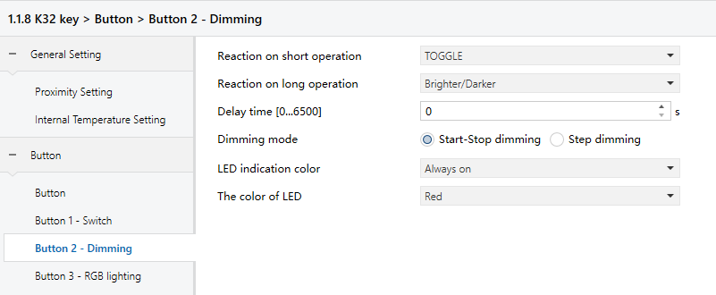
Reaction on short operation
Set the switch value sent on a short operation.
Options:
No reaction: No telegram sent.
OFF: Send “Off” telegram.
ON : Send “On” telegram.
TOGGLE: Toggle between “On” and “Off” on each operation.
Reaction on long operation
Set the dimming value sent on a long operation. It sends a dimming telegram (brighter or darker), and stops dimming upon release.
Options:
No reaction: No telegram sent.
Brighter: Send “Brighter” telegram.
Darker : Send “Darker” telegram.
Brighter/Darker: Alternate between “Brighter” and “Darker” on each operation.
NOTE:
If either the switch or dimming parameter uses TOGGLE, they interact. For instance, if the switch is ON, the next dimming action darkens the light; if OFF, it brightens.
Delay time
Set the delay before sending the telegram.
Options: 0~6500
NOTE:
The delay time applies only to short presses.
Dimming mode
This parameter appears when the parameter Reaction on long operation is not set to “No reaction”. It defines how dimming telegrams are sent.
Options:
Start-stop dimming: Send a brighten/dim telegram when dimming starts, and a stop telegram when dimming ends. No cyclic telegrams are sent.
Step dimming: Send dimming telegrams cyclically. A stop telegram is sent when dimming ends.
- Step size
This parameter is visible when “Step dimming” is selected. It sets the brightness change (percentage) for a cyclic telegram.
Options:
100%
50%
...
1.56%
- Interval of tele. cyclic send [0..25,0=send once]*0.1s
This parameter is visible when “Step dimming” is selected. It sets the time between cyclic telegrams.
Options: 0~25 (0=Send only once)
5.3.4 “RGB lighting”
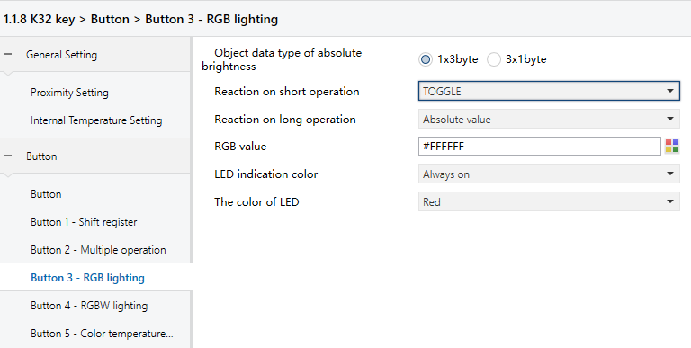
Object data type of absolute brightness
Set the data type for absolute brightness.
Options:
1*3byte: Control RGB lighting via a single 3-byte object.
3*1byt: Control RGB lighting via three 1-byte objects.
Reaction on short operation
Reaction on long operation
Set behavior for short or long presses.
Options:
No reaction
OFF
ON
TOGGLE
Absolute value
- RGB value
This parameter is visible when “Absolute value” is selected. It sets the RGB value.
Options: #000000~#FFFFFF
5.3.5 “RGBW lighting”
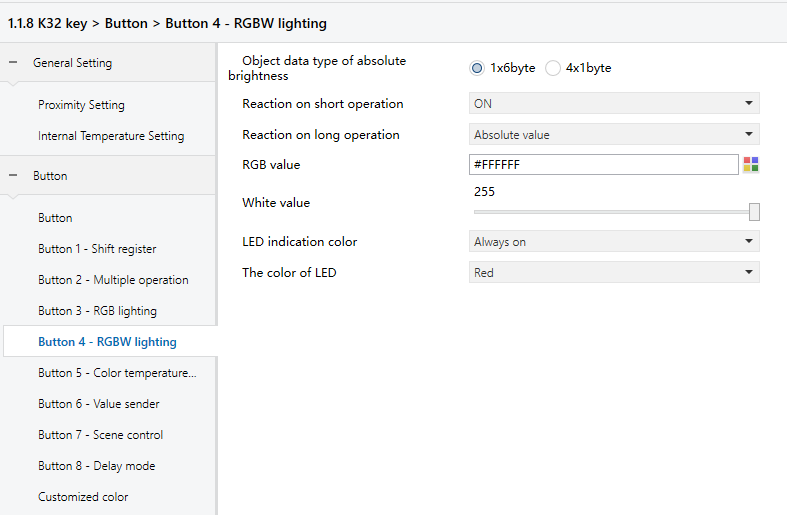
Object data type of absolute brightness
Set the data type for absolute brightness.
Options:
1*6byte: Control RGBW lighting via a single 6-byte object.
4*1byte: Control RGBW lighting via four 1-byte objects.
Reaction on short operation
Reaction on long operation
Set behavior for short/long operation.
Options:
No reaction
OFF
ON
TOGGLE
Absolute value
- White value
This parameter is visible when “Absolute value” is selected. It sets the white value.
Options: 0~255
- RGB value
This parameter is visible when “Absolute value” is selected. It sets the RGB value.
Options: #000000~#FFFFFF
5.3.6 “Colour temperature control”
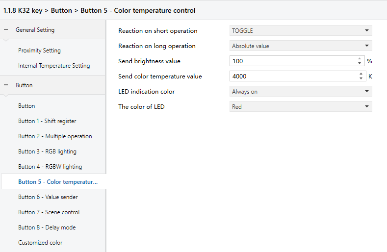
Reaction on short operation
Reaction on long operation
Set behavior for short/long operation.
Options:
No reaction
OFF
ON
TOGGLE
Absolute value
- Send brightness value
This parameter is visible when “Absolute value” is selected. It sets the brightness value.
Options: 0~100
- Send colour temperature value
This parameter is visible when “Absolute value” is selected. It sets the colour temperature value.
Options: 0~10000
5.3.7 “Value sender”
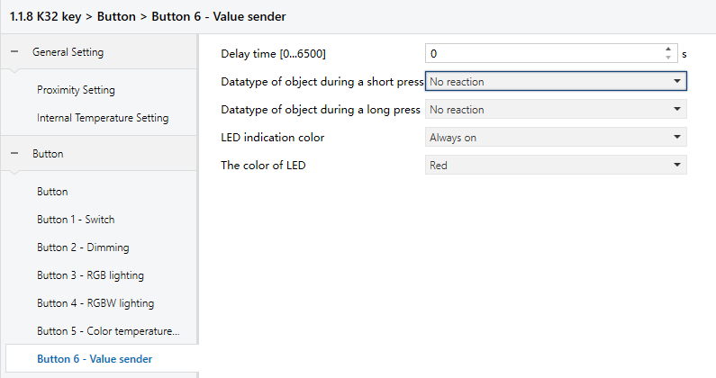
Delay time
Set the delay before sending telegrams.
Options: 0~6500
Datatype of object during a short press
Datatype of object during a long press
Select the data type for telegrams sent on short or long presses.
Options:
No reaction
1bit value[ON/OFF]
2bit value[0..3]
4bit value[0..15]
1byte signed value[-128..127]
1byte unsigned value[0..255]
1byte percentage[0-100%]
2byte signed value[-32768..32767]
2byte unsigned value[0..65535]
2byte float value
4byte signed value
4byte unsigned value
4byte float value
14byte string
- Reaction to short operation
- Reaction to long operation
This parameter is visible when the data type is not set to “No reaction”.
If 1-bit (ON/OFF) is selected:
Options:
none
off
on
toggle
For other types. Value ranges depend on the previously selected data type.
Options:
none
send value 1
send value 2
send value 1 <-> send value 2
5.3.8 “Scene control”
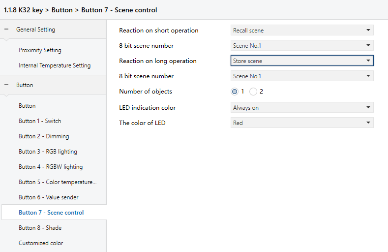
Reaction on short operation
Reaction on long operation
Set whether the press recalls or stores a scene.
Options:
No reaction
Recall scene
Store scene
- 8 bit scene number
Visible when reaction is not “No reaction”. Select the scene number.
Options: Scene NO.1 ~ 64 (Telegram values: 0~63)
- Number of objects
Visible when “Reaction on long operation” is not “No reaction”.
Set whether short and long presses use a shared or separate object.
Options: 1/2
5.3.9 “Shade”
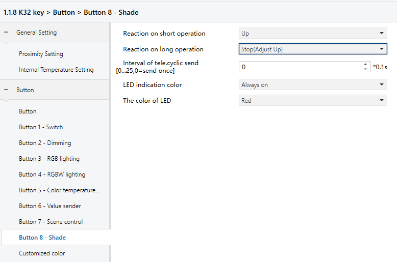
Reaction on short operation
Reaction on long operation
Set the action triggered by a short/long press.
Options:
No reaction
Up
Down
Up/Down
Stop(Adjust Up)
Stop(Adjust Down)
Stop(Adjust Up/Down)
- Interval of tele. cyclic send [0..25,0=send once]*0.1s
Visible when a “Stop(Adjust…)” option is selected. It defines the interval between cyclic telegrams.
Options: 0~25 (0 = Send only once)
5.3.10 “Shift register”
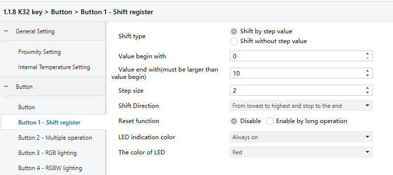
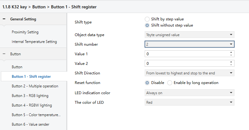
Shift type
Choose how values are shifted.
Options:
Shift by step value: Set start and end values and the increment (direction from low to high) or decrement (direction from high to low) for each shift.
Shift without step value: Specify up to 10 fixed values to be sent sequentially with each shift operation.
The following parameters appear when the “Shift by step value” is selected.
- Value begin with
Set the starting value.
Options: 0~240
- Value end with(must be larger than value begin with)
Set the ending value.
Options: 1~250
NOTE:
The ending value must be greater than starting value.
- Step size
Set the step value to increment or decrement with each shift.
Options: 0..240
The following parameters appear when the “Shift without step value” is selected.
- Object datatype
Set the data type for the shift object.
Options:
1 byte unsigned value
Scene number
HVAC mode
- Shift number
Set the number of shift values (maximum 10).
Options: 0/1/2../10
- Value x (x=1~10)
Set the value to be sent at each shift step. Valid range depends on the selected data type.
Options: 0~255/Scene NO1~64/Comfort mode/Standby mode/Economy mode/Frost/heat protection
Shift Direction
Set the shift direction.
Options:
From lowest to highest and stop to the end
From highest to lowest and stop to the begin
From lowest to highest and cyclically
From highest to lowest and cyclically
Reset function
Enable or disable the shift reset function.
Options:
Disable
Enable by long operation: Resets the shift to the starting position via a long operation.
5.3.11 “Multiple operation”
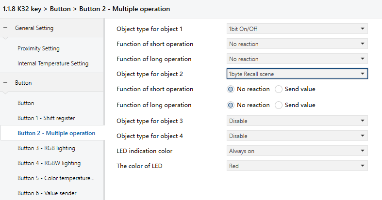
Object type for object x (x=1~4)
Set the data type to be sent during short/long operation.
Options:
Disable
1Bit On/Off
1Bit Up/Down
1Byte Recall Scene
1Byte Store Scene
1Byte Percentage
1Byte Unsigned value
Function of short operation
Function of long operation
Define the action for each operation: either “No reaction” or “Send Value” (the value is set in the next parameter).
Value x... (x=1~2)
Visible when the object type is set to “1Byte Recall Scene”, “1Byte Store Scene”, “1Byte Percentage”, or “1Byte Unsigned value”. It specifies the value to be sent. The valid range depends on the selected data type in Object type for object x.
5.3.12 “Delay mode”
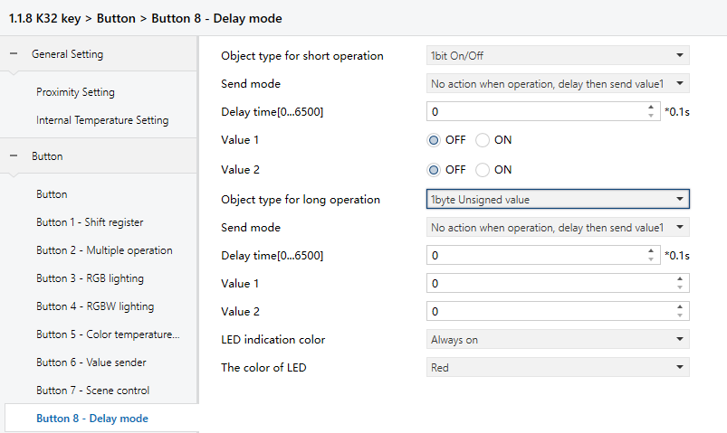
Object type for short operation
Object type for long operation
Set the data type to be sent during short/long operation.
Options:
Disable
1Bit On/Off
4Bit Dimming
1Byte Unsigned value
Send mode
Set how the value is sent.
Options:
No action when operation,delay then send value1
No action when operation,delay then send value2
Send value1 when operation,delay then send value2
Send value2 when operation,delay then send value1
Delay time [0..6500]s
Set the delay time.
Options: 0~6500
Value x (x=1~2)
Set the values to be sent. The valid range depends on the selected data type.
5.3.13 “Customized color”
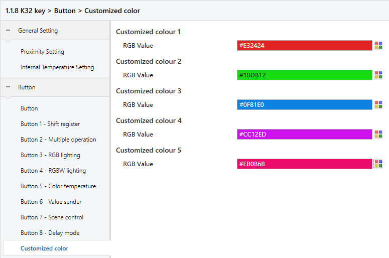
Customized colour x (x=1~5)
-RGB value
Customize the LED color. Users can customize up to 5 colors.
Options: #000000~#FFFFFF
5.4 Parameter setting interface “Logic function setting”
The Logic Function Setting interface, shown in Figure 5.4, allows the configuration of up to eight logic functions.
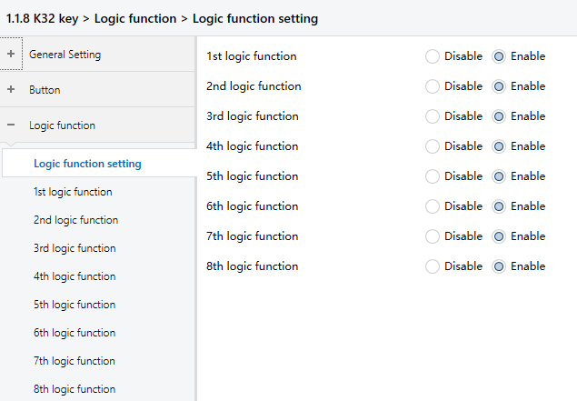
Figure 5.4: Logic function setting interface
X logic function
Enable or disable a specific logic function, as shown in Figure 5.4.
Options:
Disable
Enable
Function of channel
Set the logic function of the channel, as shown in 5.4.1.
Options:
AND
OR
XOR
Gate forwarding
Threshold comparator
Format convert
Gate calculation
AND/OR/XOR: These options share similar parameters and communication objects, with the only difference being the logic algorithm used. The following sections use one of these options as an example to illustrate the settings.
5.4.1 “AND/OR/XOR”
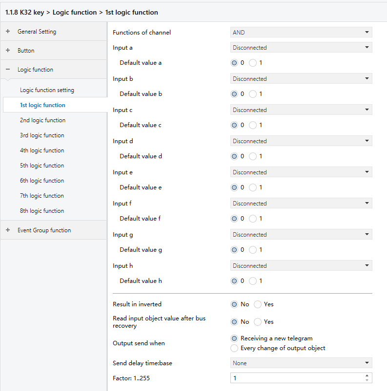
Figure 5.4.1: Logic - AND/OR/XOR interface
Input a/b/c/d/e/f/g/h
Configure whether logic input x is involved in the operation and whether it is used as-is or inverted.
Options:
Disconnected: Not used.
Normal: Input is used as-is.
Inverted: Input is inverted before being used.
NOTE:
The initial value of the input is not inverted.
Default value
Set the initial value of the logic input x.
Options:
0
1
Result is inverted
Determine whether the result of the logic operation should be inverted.
Options:
No: Output the result as-is.
Yes: Invert the result before outputting.
Read input object value after bus recovery
Specify whether a read request should be sent to the logic input object after bus power recovery or programming.
Options:
No
Yes
Output send when
Set the condition for sending the logic result to the bus.
Options:
Receiving a new telegram: Send result whenever a new logical input is received.
Every change of output object: Send result only when it changes.
NOTE:
During the initial logic operation, the result will be sent even if it hasn't changed.
Send delay time
Set the delay before the logic result is sent to the bus. The delay is calculated as:
Delay time = Base × Factor (If the “Base” is set to "None", there is no delay.)
Base:
None
0.1s
1s
2s
5s
10s
25s
Factor: 1..255
5.4.2 “Gate forwarding”
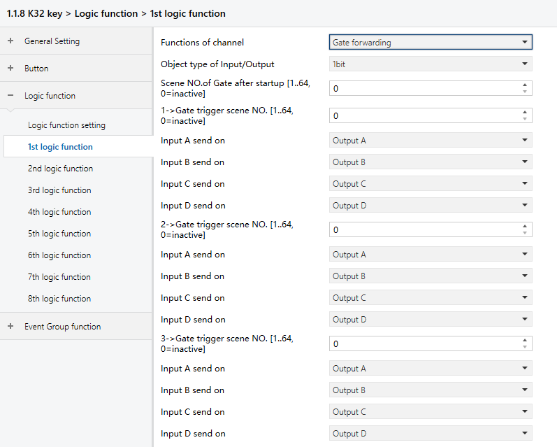
Figure 5.4.2: Logic function_Gate forwarding interface
Object type of Input/Output
Set the data type of the input/output.
Options:
1bit
4bit
1byte
Scene NO. of Gate after startup [1..64, 0=inactive]
Specify the initial scene forwarded by the logic gate after device startup. The scene must be configured in advance.
Options: 1.. 64, 0 = inactive.
TIP:
It is recommended to preselect the gate scene before operation; otherwise, the initial scene will be triggered by default.
z->Gate trigger scene NO.[1..64,0=inactive] (z:1~8)
Specify the scene number for logic gate forwarding. ach logic function can be configured with up to 8 trigger scenes.
Options: 1.. 64, 0 = inactive
NOTE:
If multiple “Gate Trigger Scene No.” entries within a single logic function are set to the same value, only the first matching entry will be used to determine the output.
Input A/B/C/D send on
Set the output target(s) for input x (x = A/B/C/D) after gate forwarding. Based on the configuration, an input can be forwarded to one or more outputs. The input and output values will remain the same.
Options:
Output A
Output B
...
Output B,C,D
NOTE:
If multiple “Gate Trigger Scene No.” entries within a single logic function share the same value, the corresponding “Input x send on” should be assigned to different outputs.
5.4.3 “Threshold comparator”
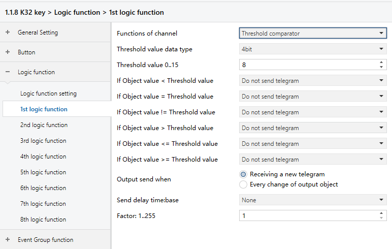
Figure 5.4.3: Logic function_Threshold comparator interface
Threshold value data byte
Set the data type used for the threshold value.
Options:
4bit: 0..15
1byte: 0..255
2byte: 0..65535
4byte: 0..4294967295
Threshold value 0..255
Set the threshold value whose range is determined by the data type.
4bit: 0..15
1byte: 0..255
2byte: 0..65535
4byte: 0..4294967295
If Object value<Threshold value
If Object value=Threshold value
If Object value!=Threshold value
If Object value>Threshold value
If Object value<=Threshold value
If Object value>=Threshold value
Set the logic result to be sent based on comparison with the threshold value.
Options:
Do not send telegram: Do nothing when the condition is met.
Send value “0”: Send telegram “0” when the condition is met.
Send value “1”: Send telegram “1” when the condition is met.
NOTE:
If there are conflicts among these conditions, the result will follow the last configured condition.
For example, if the parameter “If Object value=Threshold value" is set to "Send value 0" and “If Object value <=Threshold value" is set to "Send value 1," then when the object value equals the threshold, the logic result will send the value “1”.
Output send when
Specify when the result should be sent to the bus.
Options:
Receiving a new telegram: Send result upon each new logical input.
Every change of output object: Send result only when it changes.
NOTE:
The result will be sent during the initial logic operation even if it does not change.
Send delay time
Set the delay before the logic result is sent to the bus. The delay is calculated as:
Delay time = Base × Factor (If the “Base” is set to "None", there is no delay.)
Base:
None
0.1s
1s
2s
5s
10s
25s
Factor: 1..255
5.4.4 “Format convert”
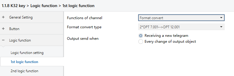
Figure 5.4.4: Logic function_Format convert interface
Format convert type
Set the conversion type for the data format.
Options:
2*DPT 1.002-->DPT 2.001
8*DPT 1.002-->DPT 5.010
DPT 1.002-->DPT 5.010
DPT 5.010-->DPT 7.001
2*DPT 5.010-->DPT 7.001
2*DPT 7.001-->DPT 12.001
DPT 5.010-->8*DPT 1.002
DPT 7.001-->2*DPT 5.010
DPT 12.001-->2*DPT 7.001
DPT 232.600(RGB)-->3*DPT 5.001(%)
3*DPT 5.001(%)-->DPT 232.600(RGB)
DPT 251.600(RGBW)-->4*DPT 5.001(%)
4*DPT 5.001(%)-->DPT 251.600(RGBW)
Output send when
Set when to send the conversion result to the bus.
Options:
Receiving a new telegram: Send result upon each new logical input.
Every change of output object: Send result only when it changes.
NOTE:
The result will be sent during the initial logic operation even if it does not change.
5.4.5 “Gate calculation”
This function is mainly used to perform calculations based on input values and output the corresponding result. Different calculation methods are available depending on the selected Input type.
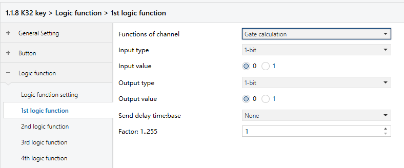
Figure 5.4.5.1: Logic function_Gate calculation_1bit interface
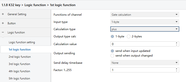
Figure 5.4.5.2: Logic function_Gate calculation_1byte interface
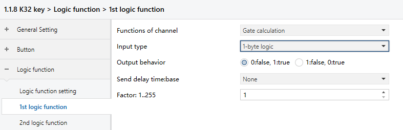
Figure 5.4.5.3: Logic function_Gate calculation_1byte logic interface
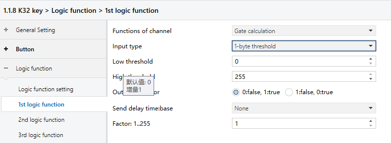
Figure 5.4.5.4: Logic function_Gate calculation_1byte threshold interface
Input type
Specify the data type of the input. The calculation method and output result vary based on the selected input type.
Options:
1-bit
2-bits
1-byte
2-bytes
1-byte logic
2-bytes logic
1-byte threshold
2-bytes threshold
TIP:
When selecting types in pairs (e.g., 1-bit/2-bits, 1-byte/2-bytes, 1-bit logic/2-bits logic, and 1-byte threshold/2-bytes threshold), the configuration parameters can be the same.
When the “Input type” is “1-bit” or “2-bits”, the output value is determined based on the configured input value. The following parameters are available:
- Input value
Set the input value. The available range depends on the data type specified by the Input type.
Options: 0..1/0..3
- Output type
Set the output data type.
Options:
1-bit
2-bits
1-byte
2-bytes
- Output value
Set the output value. The available range depends on the data type specified by the Output type.
Options: 0..1/0..3/0..255/0..65535
When the “Input type” is “1-byte” or “2-bytes”, the output value is determined based on the configured input value. The following parameters are available:
- Calculation type
Set the calculation type.
Options:
Disable: No calculation. The output is based on the input value (same as the 1-bit behavior).
Plus: When enabled, “Output type” and “Calculation value” can be set.
Minus: When enabled, “Output type” and “Calculation value” can be set.
Multiply: When enabled, “Output type” and “Calculation value” can be set.
Divide: When enabled, “Output type” and “Calculation value” can be set.
When “Calculation type” is “Disable”, the following parameters are available:
- Input value
Set the input value. The available range depends on the data type specified by the Input type.
Options: 0..255/0..65535
- Output type
Set the data type of the output.
Options:
1-bit
2-bits
1-byte
2-bytes
- Output value
Set the output value. The available range depends on the data type specified by the Output type.
Options: 0..1/0..3/0..255/0..65535
When “Calculation type” is “plus”, “minus”, “multiply” or “divide”, the following parameters are available:
- Output type
Set the data type of the output.
Options:
1-byte
2-bytes
- Calculation value
Set the calculation value. The available range depends on the data type specified by the Output type.
Options: 0..255/0..65535
TIP:
When “Calculation type” is set to “plus”, the “Calculation value” will be added.
When “Calculation type” is set to “minus”, this value will be subtracted.
When “Calculation type” is set to “multiply”, this value will be multiplied.
When “Calculation type” is set to “divide”, this value” will be used as the divisor.
- Output sending
Set the condition for sending the gate calculation result.
Options:
Send when input updated: Send the result to the bus each time the input is updated.
Send when output changed: Sends the result only when the output value changes.
When the “Input type” is “1-byte logic” or “2-byte logic”, the output is determined based on whether the input value is 0 and then outputs “True” or “False” accordingly. The following parameter is available:
- Output behavior
Define the outputs “True” and “False”.
Options:
0:false,1:true: If input value is “0”, the output is “0:false”. If input value is “1”, the output is “1:true”.
1:false,0:true: If input value is “0”, the output is “1:false”. If input value is “1”, the output is “0:true”.
When the “Input type” is “1-byte threshold” or “2-byte threshold”, the output is determined based on whether the input value falls within a defined range and then outputs “True” or “False” accordingly. The following parameter is available:
- Low threshold
Set the minimum threshold value. The available range depends on the data type specified by the input type.
Options: 0..255/0..65535
- High threshold
Set the maximum threshold value. The available range depends on the data type specified by the input type.
Options: 0..255/0..65535
- Output behavior
Define the outputs “True” and “False”.
Options:
0:false,1:true: When input value is beyond the threshold range, the output is “0:false”. When input value falls within the threshold range, the output is “1:true”.
1:false,0:true: When input value is beyond the threshold range, the output is “1:false”. When input value falls within the threshold range, the output is “0:true”.
Send delay time
Set the delay before the logic result is sent to the bus. The delay is calculated as:
Delay time = Base × Factor (If the “Base” is set to "None", there is no delay.)
Base:
None
0.1s
1s
2s
5s
10s
25s
Factor: 1..255
5.5 Parameter setting interface “Event Group function”
The parameter setting interface “Event Group function", shown in the Figure 5.5.1, is used to enable the event group function. Up to 8 event groups can be configured, and each group contains 8 outputs, as shown in the Figure 5.5.2.
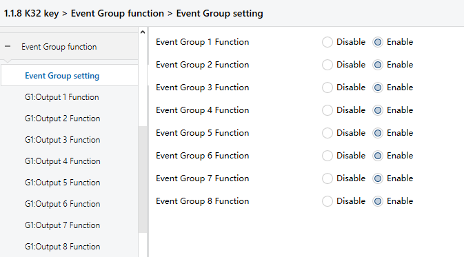
Figure 5.5.1: Event Group function interface
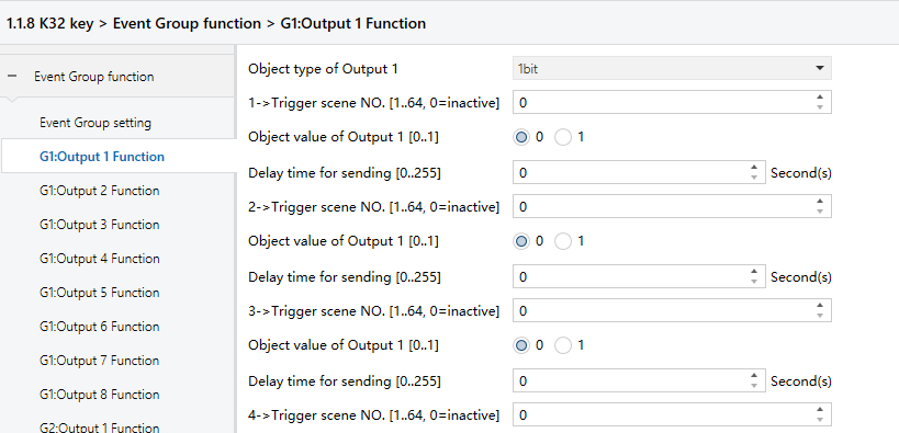
Figure 5.5.2: Groupx: Output y function interface
Event Group x Function (x:1..8)
Set to enable Event Group x.
Options:
Disable
Enable
When Event Group x Function is enabled, the configuration parameters for the group's eight outputs become available. All eight groups use the same functionality and share identical configuration options. The following settings use one output as an example.
Object type of Output y (y:1..8)
Define the data type of output y in group x.
Options:
1bit
1byte
2byte
z->Trigger scene NO.[1..64,0=inactive] (z:1..8)
Specify the scene number(s) that trigger Output y in Group x. Each output supports up to 8 scene triggers.
Options: 0 to 64, 0=inactive.
NOTE:
If multiple scene numbers are set to the same value, only the first matched trigger will be executed. The output will be sent according to the configured delay time.
Object value of Output y [0..1/0..255/0..65535]
Set the output value based on the data type of output y.
Options:
1bit 0..1
1byte 0..255
2byte 0..65535
Delay time for sending [0...255]*0.1s
Set the delay time before sending the output value to the bus.
Options: 0..255
6. Description of Communication Objects
The communication object is the exclusive means through which devices can communicate with each other on the bus.
NOTE:
In the followings tables, each flag carries significance for communication objects:
“C" indicates the enabled communication function.
“W" signifies the object value can be modified by the bus.
“R" represents the object value can be read by the bus.
“T" represents the enabled transmission function.
“U" indicates the object value can be updated.
6.1 Communication objects of “General Setting”
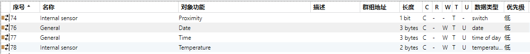
Figure 6.1: General setting communication object
No. | Object Function | Communication Object Name | Data Type | Flags | DPT |
76 | Date | General | 3bytes | C,W,TU | 11.001 date |
This communication object is used to modify the device’s date via the bus. | |||||
77 | Time | General | 3bytes | C,W,T,U | 10.001 time of day |
This communication object is used to modify the device’s time via the bus. | |||||
73 | In Operation | General | bit | C,T | 10.001 time of day |
This communication object is used to periodically send the value “1” to the bus to indicate that the device is operating normally. | |||||
78 | Temperature | Internal sensor | 2bytes | C,W,T,U | 9.001 temperature (℃) |
This communication object is visible when the “Display D&H resource parameter” is set to “Internal sensor”, and is used to send the temperature from the internal sensor to the bus. | |||||
Proximity,1 bit value Proximity,scene NO. Proximity,1 byte value | Internal sensor | 1bit 1byte | C,T | 1.001 switch 17.001 scene number 5.010 counter pulses(0..255) 5.001 percentage(0..100%) | |
This communication object is visible when the “Proximity sensor resource” is set to “Internal sensor”. When a person is detected approaching or leaving the sensing area, the object sends telegrams to the bus accordingly. The value range is determined by the selected data type. | |||||
74 | Proximity | External sensor | 1bit | C,W,T,U | 1.001 switch |
This communication object is visible when the “Proximity sensor resource” is set to “External sensor”, and is used to transmit the trigger status of the human presence detector on the bus to the K32 panel. | |||||
Table 6.1: General Setting communication object table
6.2 Communication objects of “Function page”
6.2.1 “Basic Function”
Switch
Dimming
RGB lighting
RGBW lighting
colour temperature control
Value sender

Scene control

Shade
![]()
Shift register
Multiple operation

![]()
Delay mode
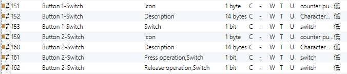
Object Function | Communication Object Name | Type | Flags | DPT | |
151 | Icon | Button 1 - {{Switching}} | 1 byte | C,W,T,U | 5.010 counter pulses(0..255) |
152 | Description | Button 1 - {{Switching}} | 14 bytes | C,W,T,U | 16.001 Character String |
153 | Switch | Button 1 - {{Switching}} | 1 bit | C,W,T,U | 1.001 switch |
161 | Press operation, Switch | Button 1 - {{Switching}} | 1 bit | C,W,T,U | 1.001 switch |
162 | Release operation, Switch | Button 1 - {{Switching}} | 1 bit | C,W,T,U | 1.001 switch |
These communication objects are used to trigger switching operations. Depending on the parameter settings, short/long press and press/release can either share one object or use separate objects. When shared, only the “Switch” object appears. If separated, “Press/Release”appears if short and long presses are not differentiated, and short/Long appears when short and long presses are distinguished. - Telegram values 0: Off 1: On The object name (in parentheses) changes according to the text entered in the Description (max 30 characters) field. If left blank, the default name will be “Btn 1 - ...”. The same also applies to the following sections. | |||||
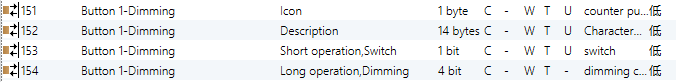
161 | Short operation, Switch | Button 1 - {{Dimming}} | 1 bit | C,W,T,U | 1.001 switch |
162 | Long operation, Switch | Button 1 - {{Dimming}} | 4 bit | C,W,T | 3.007 dimming control |
These two objects are used for switching/dimming operations and distinguish between short and long press. Obj.161: Used to trigger switch operations. - Telegram values: 0: Off 1: On | |||||
Obj.162: Used to trigger a relative dimming operation. - Telegram values: 1~7: Dim down. The higher the value within this range, the smaller the dimming step. “1” means maximum dimming step down, “7” means minimum dimming step down, and “0” means stopping dimming. 9~15: Dim up. The higher the value, the smaller the dimming step. “9” means maximum dimming step up, “15” means minimum dimming step up, and “8” means stopping dimming. | |||||
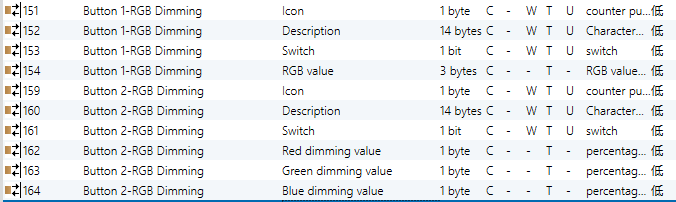
154 | RGB value | Button 1 - {{RGB Dimming}} | 3 bytes | C,T | 232.600 RGB value 3x(0..255) |
162 | Red dimming value | Button 2 - {{RGB Dimming}} | 1 byte | C,T | 5.001 percentage(0..100%) |
163 | Green Dimming value | Button 2 - {{RGB Dimming}} | 1 byte | C,T | 5.001 percentage(0..100%) |
164 | Blue Dimming value | Button 2 - {{RGB Dimming}} | 1 byte | C,T | 5.001 percentage(0..100%) |
Obj.154: Perform RGB dimming via a 3-byte object. Obj.162-164: Perform RGB dimming via three 1-byte objects. | |||||
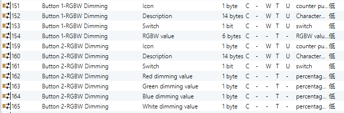
154 | RGB value | Button 1 - {{RGBW Dimming}} | 6 bytes | C,T | 251.600 RGBW value 4x(0..100%) |
162 | Red dimming value | Button 2 - {{RGBW Dimming}} | 1 byte | C,T | 5.001 percentage(0..100%) |
163 | Green Dimming value | Button 2 - {{RGBW Dimming}} | 1 byte | C,T | 5.001 percentage(0..100%) |
164 | Blue Dimming value | Button 2 - {{RGBW Dimming}} | 1 byte | C,T | 5.001 percentage(0..100%) |
165 | White Dimming value | Button 2 - {{RGBW Dimming}} | 1 byte | C,T | 5.001 percentage(0..100%) |
Obj.154: Perform RGBW dimming via a 6-byte object. Obj.162-165: Perform RGBW dimming via four 1-byte objects. | |||||
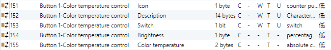
154 | Brightness | Button 1 - {{colour temperature control}} | 1 byte | C,T | 5.001 percentage(0..100%) |
155 | colour temperature | Button 1 - {{colour temperature control}} | 2 bytes | C,T | 7.600 absolute colour temperature |
Obj.154: Used to control brightness. Obj.155: Used to control colour temperature. | |||||
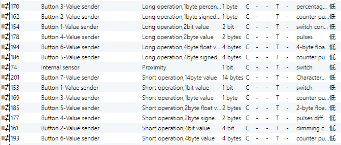
154 -201 | Short operation,1bit value 2bit value 4bit value 1byte signed value 1byte unsigned value 1byte percentage 2byte signed value 2byte unsigned value 2byte float value 4byte signed value 4byte unsigned value 4byte float value 14byte string | Button 6 - {{Value sender}} | 1bit 2bit 4bit 1byte 2byte 4byte 14byte | C,T | 1.001 switch 2.001 switch control 3.007 dimming control 6.010 counter pulses(-128..127) 5.010 counter pulses(0..255) 5.001 percentage(0..100%) 8.001 pulses difference 7.001 pulses 9.x float value 13.001 counter pulses(signed) 12.001 counter pulses(unsigned) 14.x float value 16.001 Character String |
154 -201 | Long operation,1bit value 2bit value 4bit value 1byte signed value 1byte unsigned value 1byte percentage 2byte signed value 2byte unsigned value 2byte float value 4byte signed value 4byte unsigned value 4byte float value 14byte string | Button 6 - {{Value sender}} | 1bit 2bit 4bit 1byte 2byte 4byte 14byte | C,T | 1.001 switch 2.001 switch control 3.007 dimming control 6.010 counter pulses(-128..127) 5.010 counter pulses(0..255) 5.001 percentage(0..100%) 8.001 pulses difference 7.001 pulses 9.x float value 13.001 counter pulses(signed) 12.001 counter pulses(unsigned) 14.x float value 16.001 Character String |
These two communication objects are used to send fixed values to the bus, distinguishing between short and long press operations. The value range to be sent is determined by the selected data type, which is configured via parameters. | |||||
153 | Short operation,scene | Button 1 - {{Scene control}} | 1byte | C, T | 18.001 scene control |
154 | Long operation,scene | Button 1 - {{Scene control}} | 1byte | C, T | 18.001 scene control |
These communication objects are used to send an 8-bit command to recall or store a scene. According to parameter settings, short and long press can either share one object or use separate objects. If shared, only the “Scene” object is visible; if separated, “Short/Long” object appears and distinguish between short and long operations. The parameter setting range is 1-64, but the actual value sent via the communication object is 0-63. For example, if the parameter is set to scene 1, the object sends a scene telegram with value 0. | |||||
169 | Up/Down, Blind | Button 3 - {{Blind}} | 1bit | C, W, T | 1.008 up/down |
170 | Stop/Adjust, Blind | Button 3 - {{Blind}} | 1bit | C, W, T | 1.007 step |
These two communication objects are used to control shades open, close, and stop actions. Descriptions are as follows: Obj.169: Send a telegram of controlling shades close/open actions to the bus. - Telegram values: 1: Close the shades downward 0: Open the shades upward Obj.170: Send a telegram of stopping shades movement to the bus. - Telegram values: 1: Stop | |||||
169 | Register value | Button 3 - {{Shift register}} | 1byte | C, W, T | 5.010 counter pulses |
This communication object is used to send the value of the shift register. | |||||
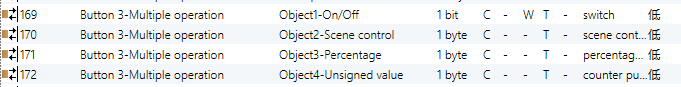
169 -172 | Object-On/Off Object-Up/Down Object-SceneControl Object-Percentage Object-Unsigned value | Button 3 - {{Multiple operation}} | 1bit 1bit 1byte 1byte 1byte | C,W,T C,W,T C,T C,T C,T | 1.001 switch 1.008 up/down 18.001 scene control 5.001 percentage(0..100%) 5.010 counter pulses |
This communication object is used for multiple operations, supporting activation of up to 4 operations simultaneously. With these objects, a single action can send 4 different types of values to the bus at once. The range of values to be sent is determined by the selected data type, which is configured via parameters. | |||||
169 170 177 | Short operation,on/off Dimming Unsigned value | Button 3 - {{Delay mode}} | 1bit 4bit 1byte | C,T | 1.001 switch 3.007 dimming 5.010 counter pulses |
169 170 177 | Long operation,on/off Dimming Unsigned value | Button 3 - {{Delay mode}} | 1bit 4bit 1byte | C,T | 1.001 switch 3.007 dimming 5.010 counter pulses |
These two communication objects are used to send delayed mode values to the bus, with separate handling for short and long press operations. The range of values sent is determined by the data type selected in the parameter settings. | |||||
6.3 Communication objects of “Logic function”
6.3.1 “AND/OR/XOR”
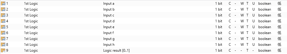
Figure 6.3.1: Logic function_AND/OR/XOR communication object
Number | Object function | Name | Type | Flags | DPT |
1/... | Input x | 1st /.../8th Logic | 1bit | C,W,T,U | 1.002 boolean |
This object is used to receive the value of logic Input x. | |||||
9 | Logic result[0..1] | 1st /.../8th Logic | 1bit | C,T | 1.002 boolean |
This object is used to send the result of a logical operation. | |||||
Table 6.3.1: Logic function_AND/OR/XOR communication object
6.3.2 “Gate forwarding”
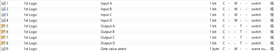
Figure 6.3.2: Logic function_Gate forwarding communication object
No. | Object function | Name | Type | Flags | DPT |
9 | Gate value select | 1st /.../8th Logic | 1byte | C,W | 17.001 scene number |
This object is used to select the scene forwarded by the logic gate. | |||||
1/../4 | Input x | 1st /.../8th Logic | 1bit 4bit 1byte | C,W | 1.001 switch 3.007 dimming control 5.010 counter pulses(0..255) |
This object is used to receive the value of logic gate Input x. | |||||
5/../8 | Output x | 1st /.../8th Logic | 1bit 4bit 1byte | C,T | 1.001 switch 3.007 dimming control 5.010 counter pulses(0..255) |
This object is used to output the value after logic gate forwarding. The output value is the same as the input value, but one input can be forwarded into one or more outputs, which are determined by parameters. | |||||
Table 6.3.2: Logic function_Gate forwarding communication object
6.3.3 “Threshold comparator”
![]()
Figure 6.3.3: Logic function_Threshold comparator communication object
No. | Object function | Name | Type | Flags | DPT |
4 | Threshold value input | 1st /.../8th Logic | 4bit 1byte 2byte 4byte | C,W, U | 3.007 dimming control 5.010 counter pulses(0..255) 7.001 pulses 12.001 counter pulses |
This object is used to input a threshold value. | |||||
9 | Threshold value output 1bit | 1st /.../8th Logic | 1bit | C,T | 1.002 boolean |
This object sends the logic result, specifically by transmitting the value obtained after comparing the input threshold value with the parameter-set threshold value. | |||||
Table 6.3.3: Logic function_Threshold comparator communication object
6.3.4 “Format convert”

2*DPT 1.002-->DPT 2.001: Convert two 1bit values into a 2bit value, for example, Input bit1=1, bit0=1--> Output 2bit=3.
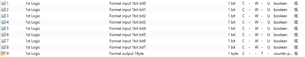
8*DPT 1.002-->DPT 5.010: Convert 8 1bit values into a 1byte value, for example, Input bit3=1, bit2=1, bit1=1, bit0=1, with other bits being 0 --> Output 1byte=15.
![]()
DPT 1.002-->DPT 5.010: Convert a 1bit value into a 1byte value, for example, Input 1bit=1--> Output 2byte=1, even though the value remains the same, the data type of the value has changed.
![]()
DPT 5.010-->DPT 7.001: Convert a 1byte value into a 2byte value, for example, Input 1byte=125--> Output 2byte=125, even though the value remains the same, the data type of the value has changed.

2*DPT 5.010-->DPT 7.001: Convert 2 1byte values into a 2byte value, for example, Input 1byte-low = 255 ($FF), Input 1byte-high = 100 ($64) --> Output 2byte = 25855 ($64 FF)

2*DPT 7.001-->DPT 12.001: Convert 2 2byte values into a 4byte value, for example, Input 2byte-low = 65530 ($FF FA), Input 2byte-high = 32768 ($80 00)--> Output 2byte = 2147549178 ($80 00 FF FA)
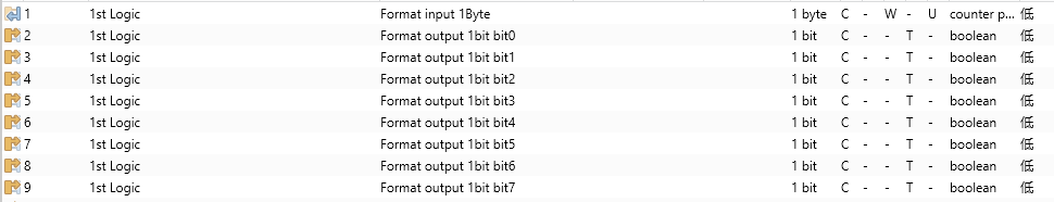
DPT 5.010-->8*DPT 1.002: Convert 1 1byte value into 8 1bit values, for example, Input 1byte=63--> Output bit0=1, bit1=1,bit2=1, bit3=1, bit4=1, bit5=0, bit6=0, bit7=0

DPT 7.001-->2*DPT 5.010: Convert 1 2byte value into 2 1byte values, for example, Input 2byte = 55500 ($D8 CC) -->Output 1byte-low = 204 ($CC), Output 1byte-high =216 ($D8)

DPT 12.001-->2*DPT 7.001: Convert 1 4byte value into 2 2byte values, for example, Input 4byte = 78009500 ($04 A6 54 9C) --> Output 2byte-low = 21660 ($54 9C), Output 2byte-high =1190 ($04 A6)

DPT 232.600(RGB)-->3*DPT 5.001(%): Convert 1 3byte value into 3 1byte values, for example, Input RGB = $78 64 C8--> Output red = 120($78) , Output green = 100 ($64) , Output blue =200 ($C8)

3*DPT 5.001(%)-->DPT 232.600(RGB): Convert 3 1byte values into 1 3byte value, for example, Input red = 150 ($96), Input green = 100 ($64), Input blue = 50 ($32)--> Output 3byte = $96 64 32
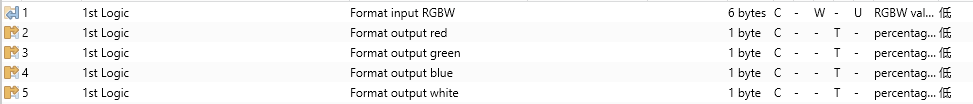
DPT 251.600(RGBW)-->4*DPT 5.001(%): Convert 1 6byte value into 4 1byte values, for example, Input RGBW = $78 63 C7 45 00 0F--> Output red = 120($78) , Output green = 99 ($63) , Output blue =199 ($C7) , Output white = 69 ($45)
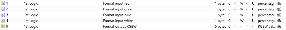
4*DPT 5.001(%)-->DPT 251.600(RGBW): Convert 4 1byte values into 1 6byte value, for example, Input red = 120 ($78), Input green = 100 ($63), Input blue = 50 ($33), Input white = 69 ($45)--> Output 6byte = $78 63 33 45 00 00
No. | Function | Communication object name | Type | Flags | DPT |
1 | Format input ... | 1st /.../8th Logic | 1bit 1byte 2byte 3byte 4byte 6byte | C,W,U | 1.001 Switch 5.001 percentage(0..100%) 5.010 counter pulses(0..255) 7.001 pulses 232.600 RGB value 3x(0..255) 12.001 counter pulses 251.600 RGBW value 4x(0..100%) |
This object is used to input the value that needs to be converted. | |||||
9 | Format output ... | 1st /.../8th Logic | 1bit 2bit 1byte 2byte 3byte 4byte 6byte | C,T | 1.001 switch 2.001 switch control 5.001 percentage(0..100%) 5.010 counter pulses(0..255) 7.001 pulses 232.600 RGB value 3x(0..255) 12.001 counter pulses 251.600 RGBW value 4x(0..100%) |
This object is used to output the converted value. | |||||
Table 6.3.4: Logic function_Format convert communication object
6.3.5 “Gate calculation”
![]()
Figure 6.3.5: Logic function_Gate calculation communication object
No. | Function | Communication object name | Type | Flags | DPT |
1 | Input... | 1st /.../8th Logic | 1bit 2bit 1byte 2byte | C,W, U | 1.002 boolean 2.001 switch control 5.010 counter pulses(0..255) 7.001 pulses |
This object is used to input the value for the calculation. | |||||
9 | Output... | 1st /.../8th Logic | 1bit 2bit 1byte 2byte | C,T | 1.002 boolean 2.001 switch control 5.010 counter pulses(0..255) 7.001 pulses |
This object is used to send the result of the gate calculation. | |||||
Table 6.3.5: Logic function_Gate calculation communication objec
6.4 Communication objects of “Event Group”
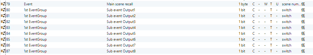
Figure 6.4: Event Group communication object
No. | Function | Communication object name | Type | Flags | DPT |
79 | Main scene recall | Event | 1byte | C,W,T,U | 17.001 scene number |
This communication object triggers each output in the event group to send a specific value to the bus by recalling the corresponding scene number. - Telegram values: 0..63 | |||||
80... | Sub event Output 1..8 | 1st /.../8th Event Group | 1bit 1byte 2byte | C,T | 1.001 switch 5.010 counter pulses(0..255) 7.001 pulses |
When a scene is recalled, this object sends the corresponding output value to the bus. If no output is configured for the scene, no telegram will be sent. Up to 8 event groups can be configured, with each group supporting up to 8 outputs. | |||||
Table 6.4: Event Group communication object