akubela panels can connect to various ZigBee devices, including sensors, IR controllers, thermostats, smart switches, and more. Before pairing the ZigBee devices with akubela panels, you should put them in the pairing mode.
Note
The transmission distances of ZigBee signal may vary by environmental characteristics and other factors. For optimal performance, add ZigBee devices to the akubela panels within the same room.
The following are the instructions on how to put various ZigBee devices into pairing mode.
Sensors
Device | Power Supply/Battery Needed | Put Device into Paring Mode | |
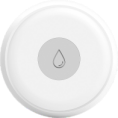
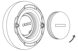
Smart Flood Sensor
| CR2032 |
|
|
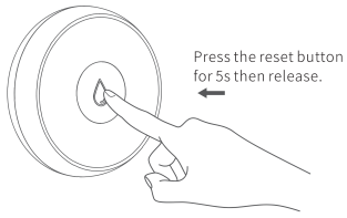
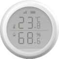
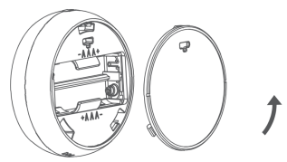
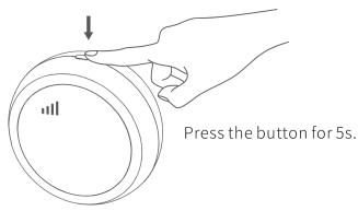
Smart Temperature and Humidity Sensor
| AAA Battery*2 |
| |
Smart Motion Sensor
| CR123A |
|
|
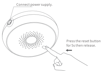
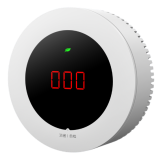
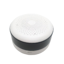
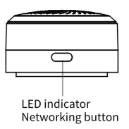
Smart Gas Sensor
| AC 220V Input (via power adapter, outputs 12V DC) |
|
|
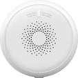
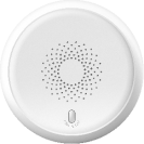
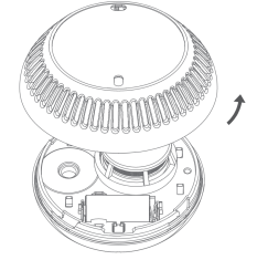
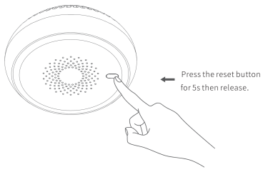
Smart Smoke Sensor
| CR123A |
|
|
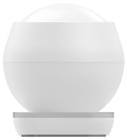
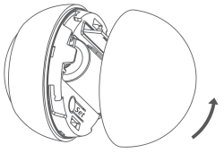
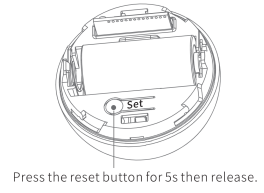
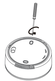
Smart CO Sensor
| CR123A |
|
|
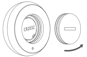
Smart Emergency Button
| CR2032 |
|
|
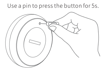
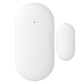
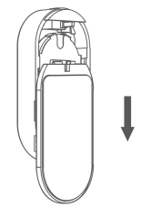
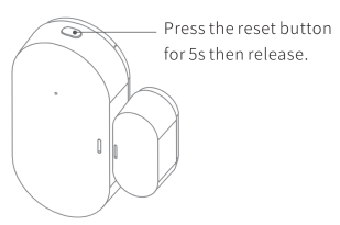
Smart Door/Window Sensor
| CR2032 |
|
|
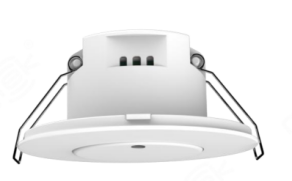
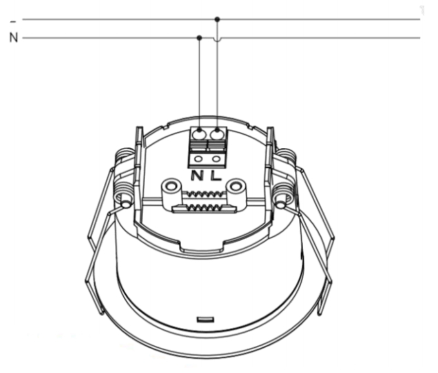
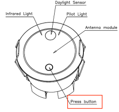
Human Presence Sensor
| 100-220VAC
|
|
|

Plugs
Device | Power Supply | Put Device into Paring Mode | |
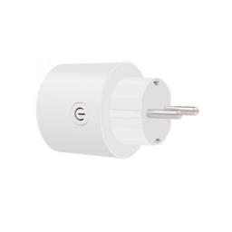
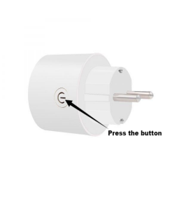
Smart Plug - EU Version
| 100-240VAC | Press and hold the button for about 6s until the blue light flashes. |
|
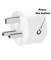
Smart Plug - UK Version
| 100-240VAC | Press and hold the button for about 6s until the blue light flashes. |
|
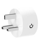
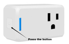
Smart Plug - US Version
| 100-240VAC | Press and hold the button for about 6s until the blue light flashes. |
|
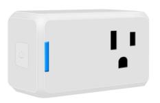
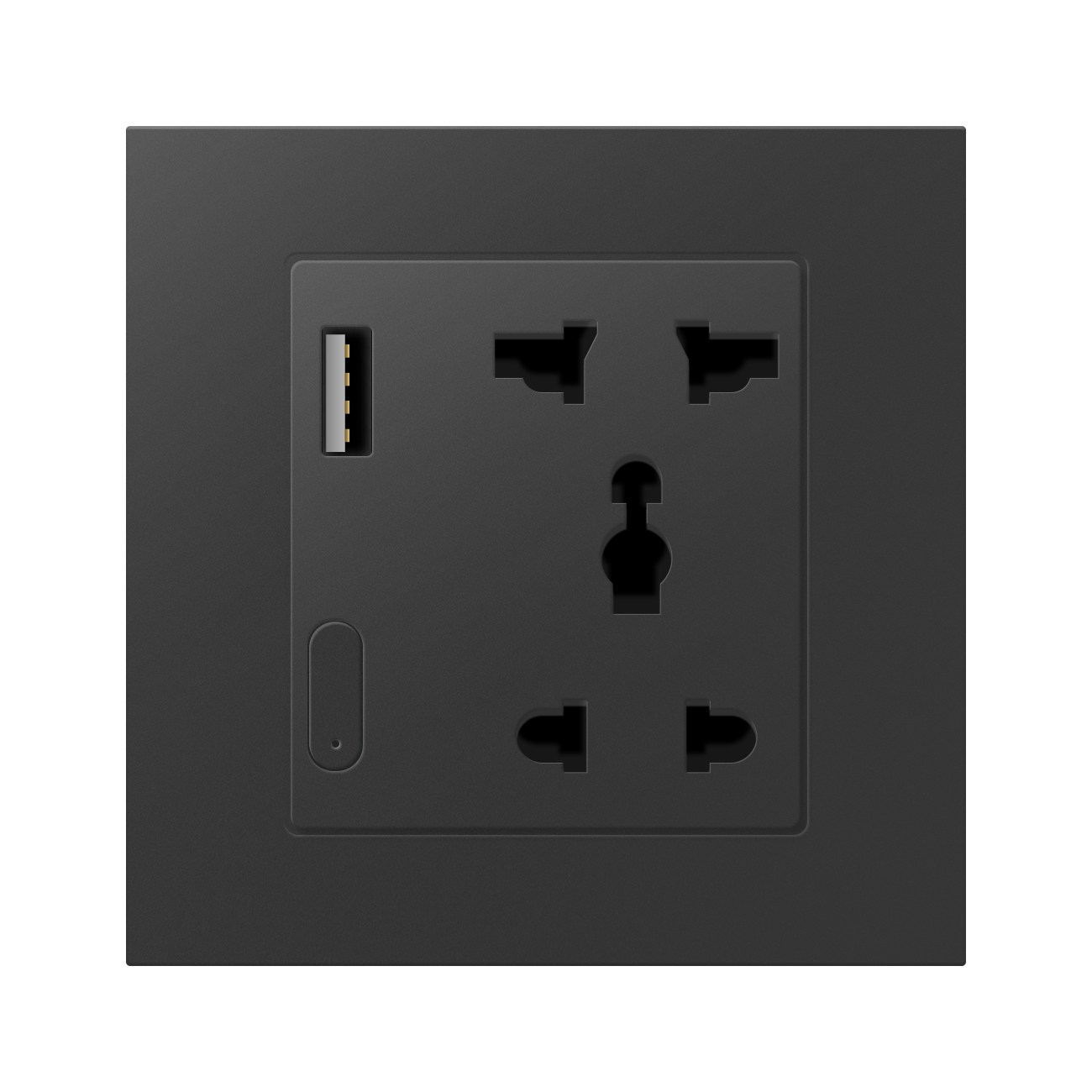
Smart Socket With USB
|
100-240VAC | Press and hold the button for 5-8 seconds until the red light flashes quickly. NOTE: The red indicator is relatively dim and may require shading the area to see it clearly. If the blue light appears instead, press the button once to switch to red. |
Switch Panels
Device | Power Supply/Battery Needed | Put Device into Paring Mode | |
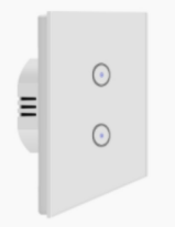
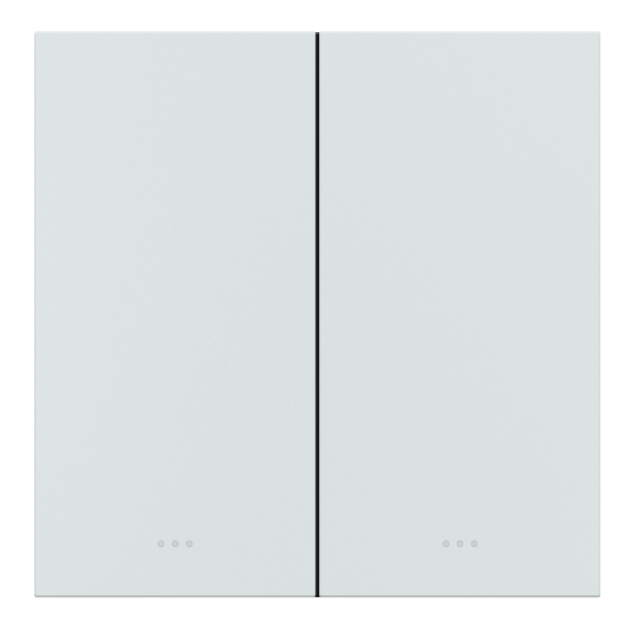
1/2/3 Gang Touch Switch-EU
|
100-240VAC | Press any of the touch buttons for 6~8 seconds until the indicator light flashes. |
|
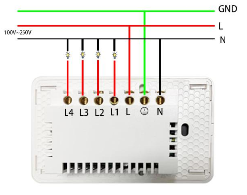
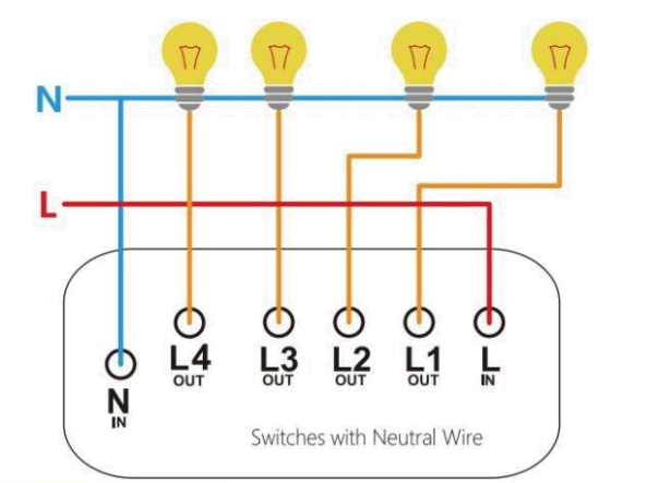
1/2/3/4 Gang Touch Switch-US
|
100-250VAC | Press and hold any button for 5~10 seconds until the red indicator light flashes. |
|
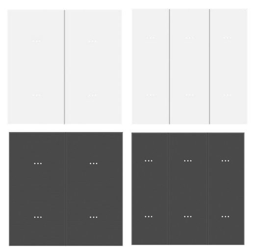
1/2/3/4 Gang Key Switch-EU
|
100-240VAC | Press and hold any button for 5~8 seconds until the white indicator light flashes. | |
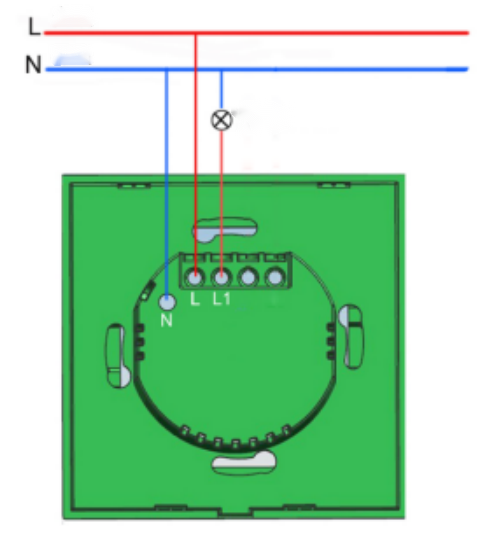
1/2/3/4 Gang Key Switch (No Neutral)-EU
|
100-240VAC | Press and hold any button for 5~8 seconds until the white indicator light flashes. | |
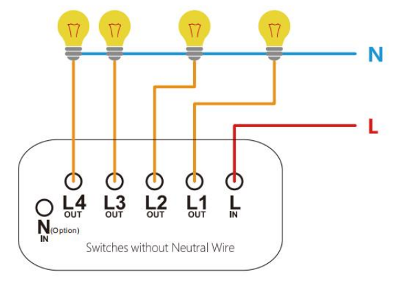
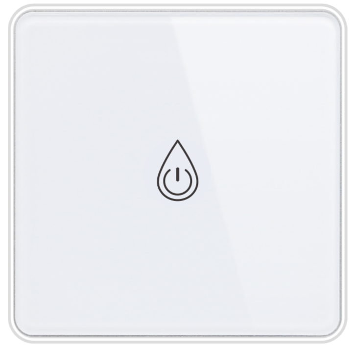
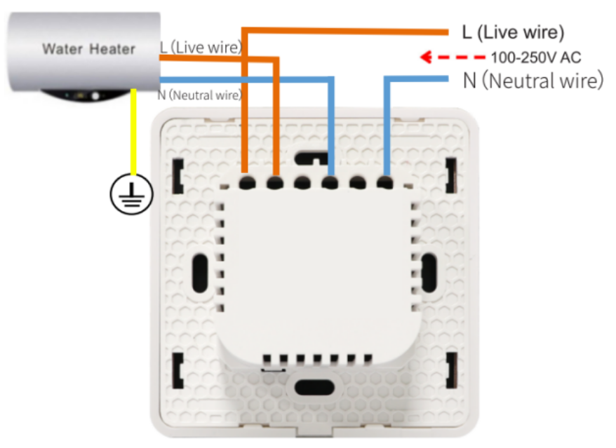
Smart Boiler Switch-EU
|
100-240VAC | Press and hold the button for 5 seconds until the red indicator light flashes. | |
4/6-button Scene Panel (Battery Powered)-EU
| CR2032, 3V | Press and hold any button for 6~10 seconds until the indicator light flashes. | |
4/6-button Scene Panel-EU
| 100-250VAC
| Press and hold any button for 6~11 seconds until the indicator light flashes. | |
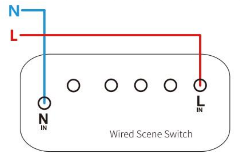
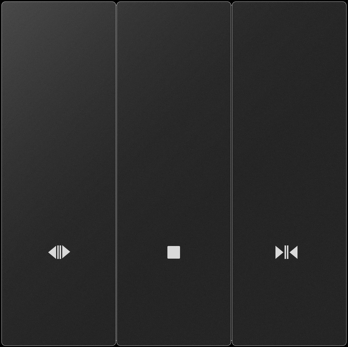
Curtain Control Panel-EU
|
100-240VAC | Press and hold any button for about 10 seconds until the indicator light flashes rapidly. | |
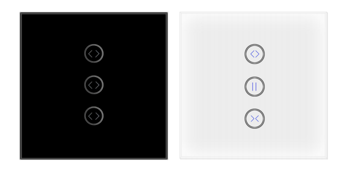
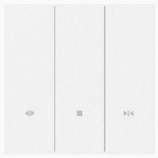
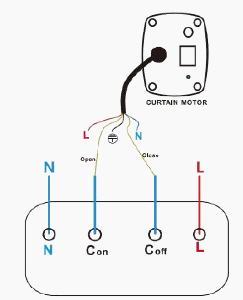
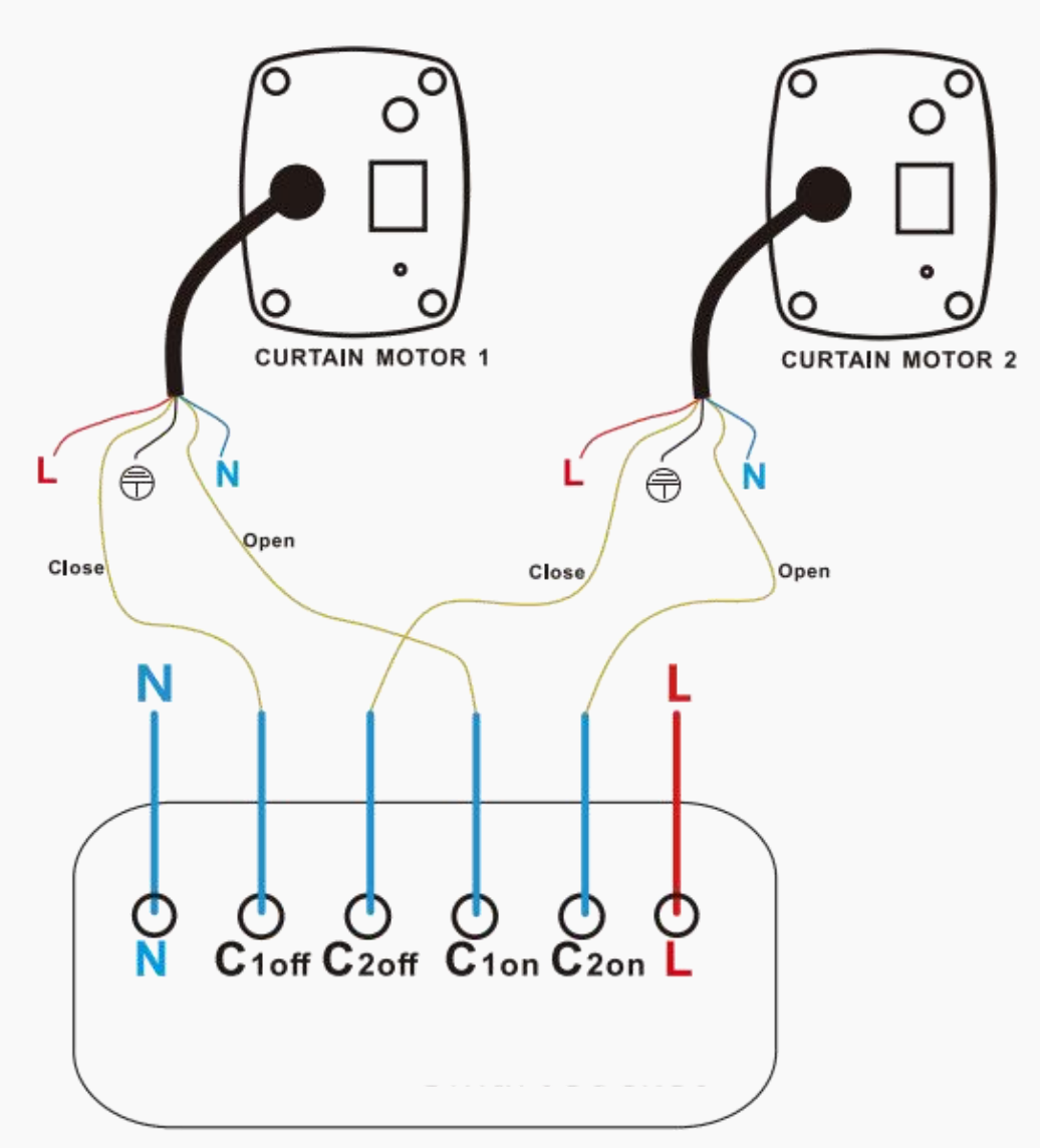
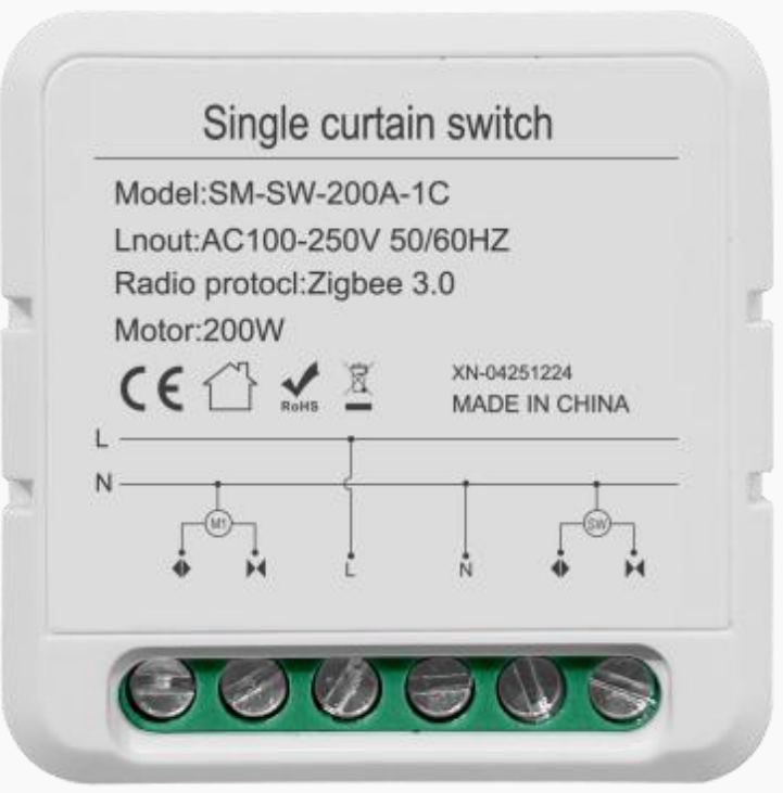
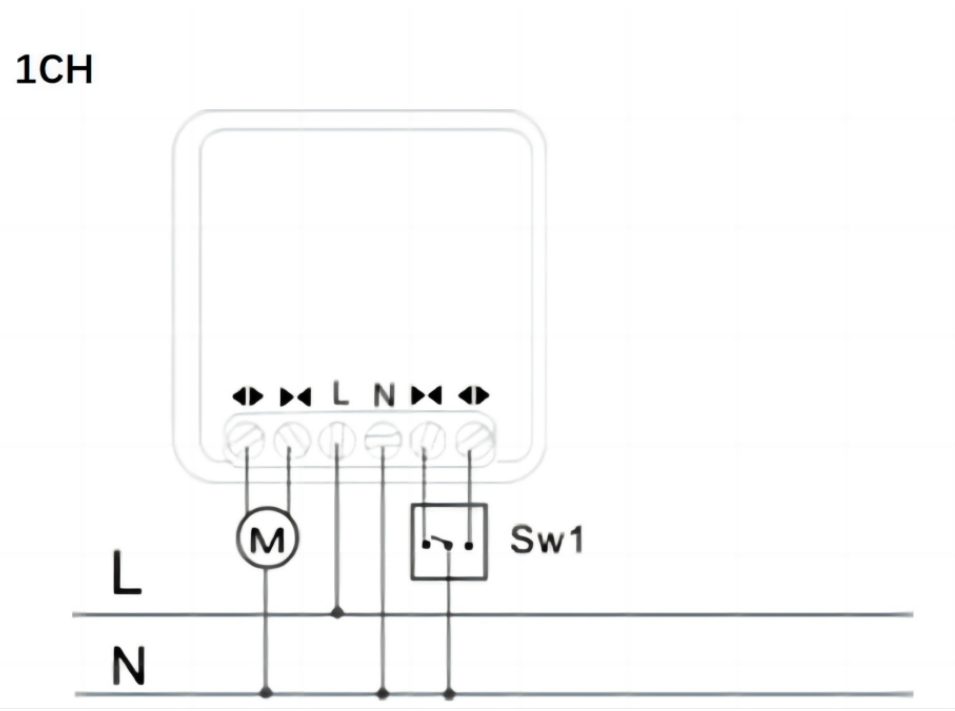
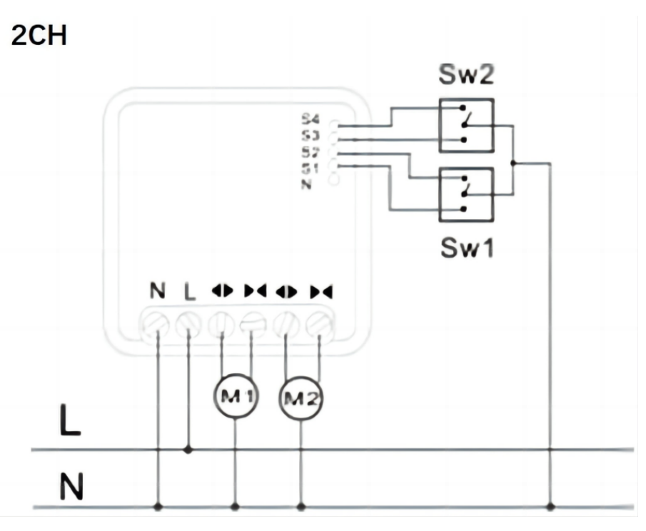
1/2 Gang Curtain Switch-EU
| 100-250VAC
1-Gang
2-Gang | Press and hold any button for 5~8 seconds until the white indicator light flashes rapidly. |


Switch Modules
Device | Power Supply | Put Device into Paring Mode | |
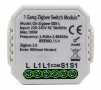
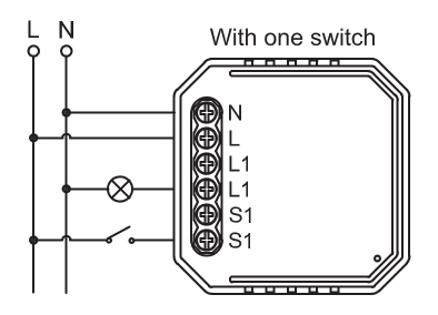
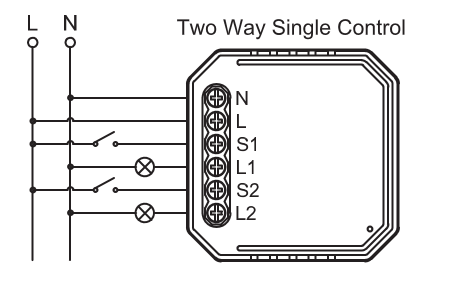
1 Gang Switch Module
|
100-240VAC | Switch on/off the traditional switch for 5 times until the indicator light flashes. |
|
2 Gang Switch Module
|
100-240VAC | Switch on/off the traditional switch for 5 times until the indicator light flashes. Or press the reset key for about 5s using a paperclip or needle until the indicator light flashes. | |
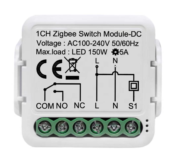
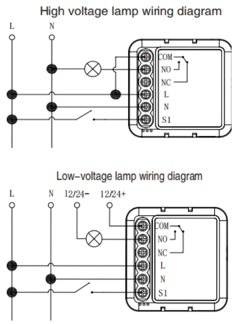
1 Gang Dry Contact Switch Module
| 100-240VAC
| Switch on/off the traditional switch for 5 times until the indicator light flashes. Or press the reset button for about 10s until the indicator light flashes. | |
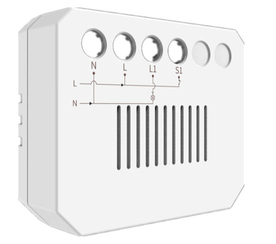
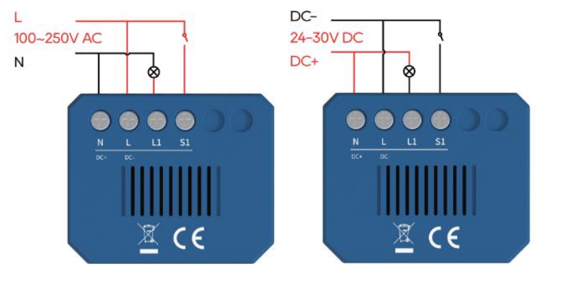
akubela 1/2 Gang Switch Module
|
100 ~ 240VAC, 50/60Hz or 24V DC | Press the reset button for about 5s until the blue light flashes. |


Thermostats
Device | Power Supply/Battery Needed | Put Device into Paring Mode | |
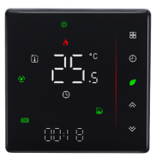
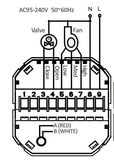
Fan Coil Thermostat (220V/2-Pipe)
|
95-240VAC, 50-60HZ |
|
|
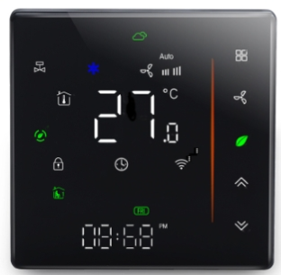
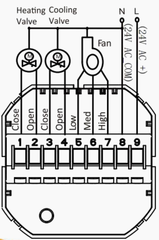
Fan Coil Thermostat (24V/4-Pipe)
|
24V C/DC,50/60Hz | ||
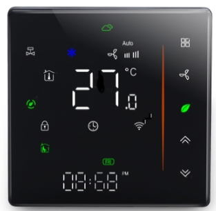
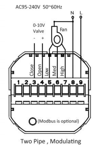
Fan Coil Thermostat (0-10V/2-Pipe)
|
95-240VAC, 50/60Hz |
| |
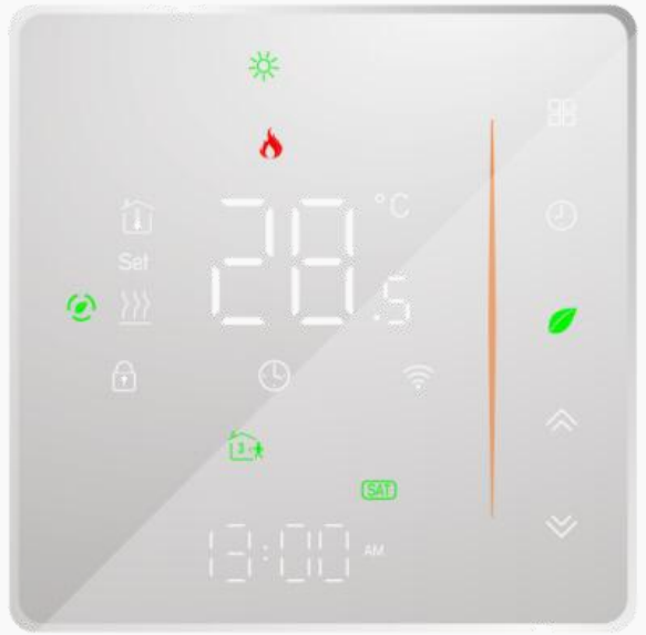
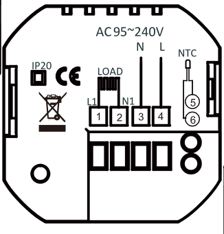
Heating Thermostat
|
95-240VAC, 50/60HZ |
 to turn off the thermostat.
 until the icon
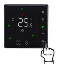
Lighting Devices
Device | Power Supply/Battery Needed | Put Device into Paring Mode | |
LED Dimmer
|
12-36VDC/10.5A |
|
|
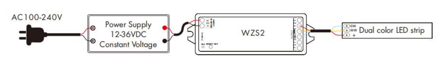
CCT LED Controller
|
12-36VDC/10.5A | ||
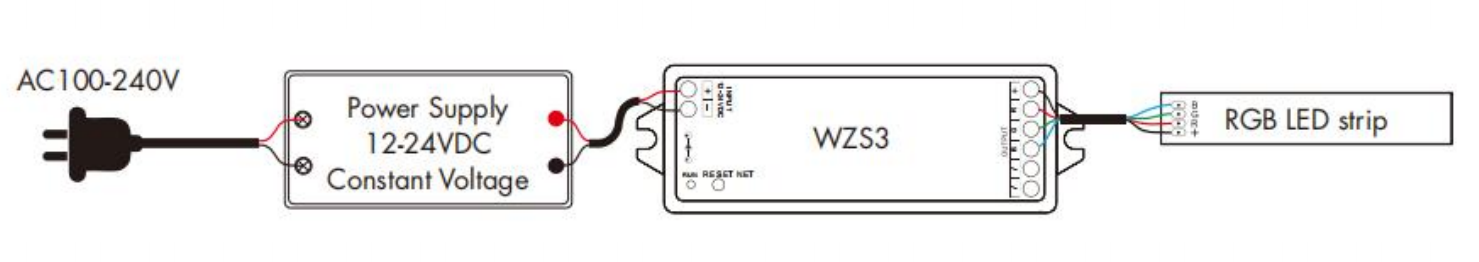
RGB LED Controller
|
12-24VDC/12.5A | ||
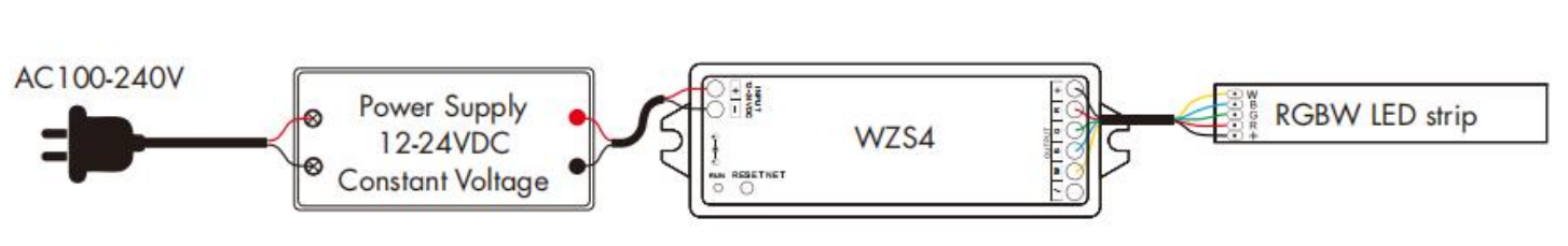
RGBW LED Controller
|
12-24VDC/12.5A | ||
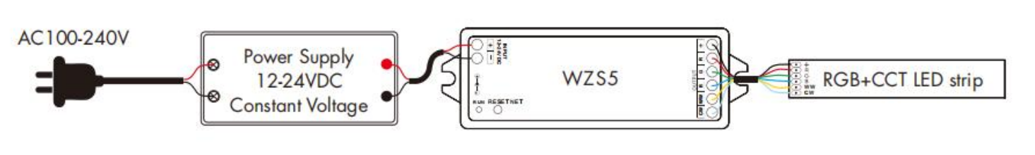
RGB+CCT LED Controller
|
12-24VDC/15.5A | ||
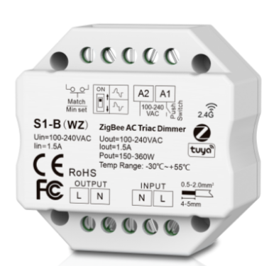
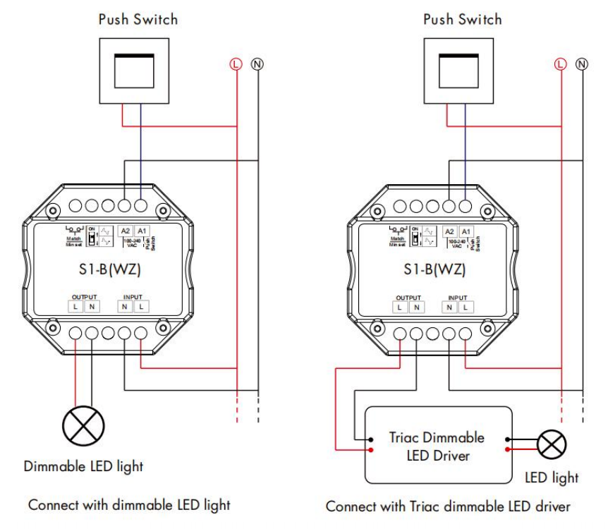
ZigBee AC Triac Dimmer
|
100-240VAC | Press the black button on the side twice or hold it for 5-8 seconds. | |
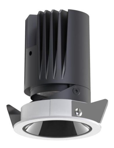
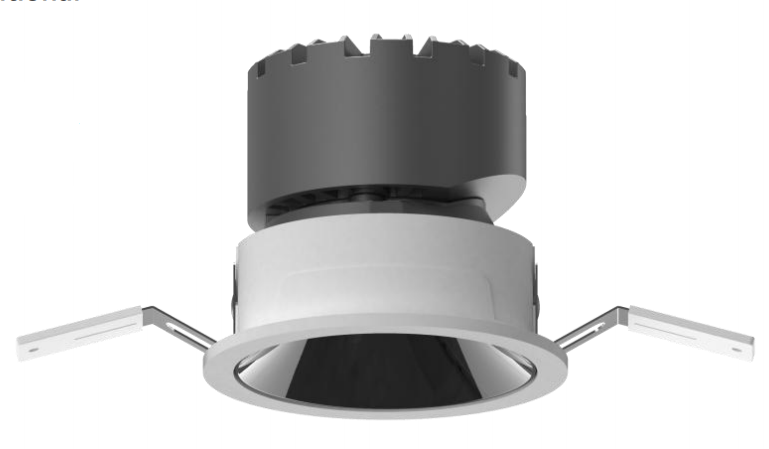
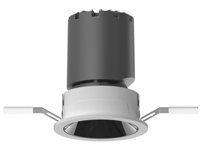
Spotlight (55mm/10W)
| 220-240VAC |
| |
Spotlight (75mm/9W)
| 220-240VAC | ||
Spotlight (55mm/9W)
| 220-240VAC | ||
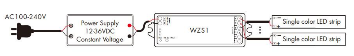
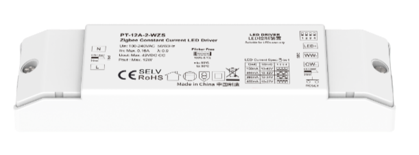
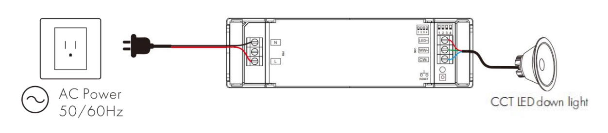
Zigbee Constant Current LED Driver
|
100-240VAC | Press the network reset button for 5 times (or toggle the power 5 times consecutively) to clear previous connected network, and the load light strip will blink in a breathing pattern, indicating that the device is in pairing mode. | |
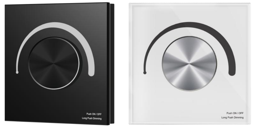
Zigbee Triac Dimmer Panel
|
100-240VAC | Press the black button on the module twice quickly, and the blue indicator light on the knob panel flashes rapidly. |


IR Controllers
Device | Power Supply | Put Device into Paring Mode | |
IR21/IR22 | 5VDC/1A |
|
|
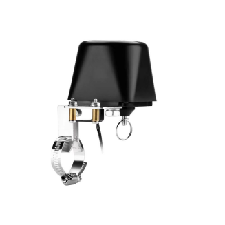
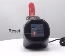
Smart Valves
Device | Power Supply | Put Device into Paring Mode | |
| 100-240VAC Input (via power adapter, outputs 12VDC/1.5A) | Press and hold the reset button until the blue light flashes. |
|
Radiator Thermostat Valve
| AA Battery*2 | Press and hold the ”-“ button on the panel until the ZigBee icon flashes. |
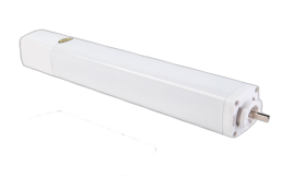
Shade Motors
Device | Power Supply | Put Device into Paring Mode | |
Shade Motor
|
100-240VAC | Press the button four times, then long-press it until the indicator light flashes. |
|
Zigbee Motor
| |||
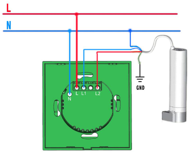
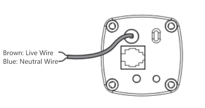
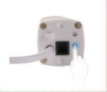
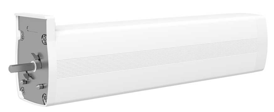
1 /2 Gang Curtain Module
|
100-240VAC | Press and hold the round button on the back cover for about 5 seconds, until the indicator light flashes rapidly. |
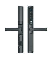
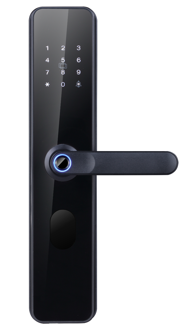
Smart Locks
Device | Battery Nedded | Put Device into Paring Mode |
F2 Smart Lock
| AAA Battery *4 |
|
C6 Smart Lock
| AA Battery *4 |
|
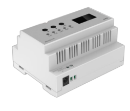
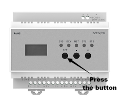
Air Conditioning Gateways
Device | Power Supply | Put Device into Paring Mode | |
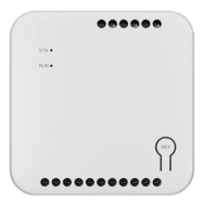
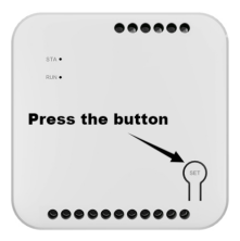
Central AC Controller - Outdoor
| 12VDC | Press and hold the Set button until a prompt is heard. |
|
Central AC Controller - Indoor
| By indoor unit | Press and hold the Set button until a prompt is heard. |
|
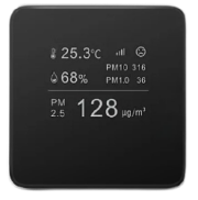
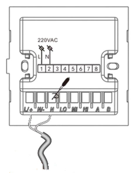
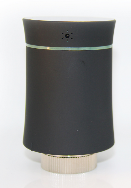
Air Quality Detectors
Device | Power Supply | Put Device into Paring Mode | |
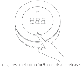
|
100-220VAC | Press and hold the button for about 5s until the entire network icon lights up. |
|