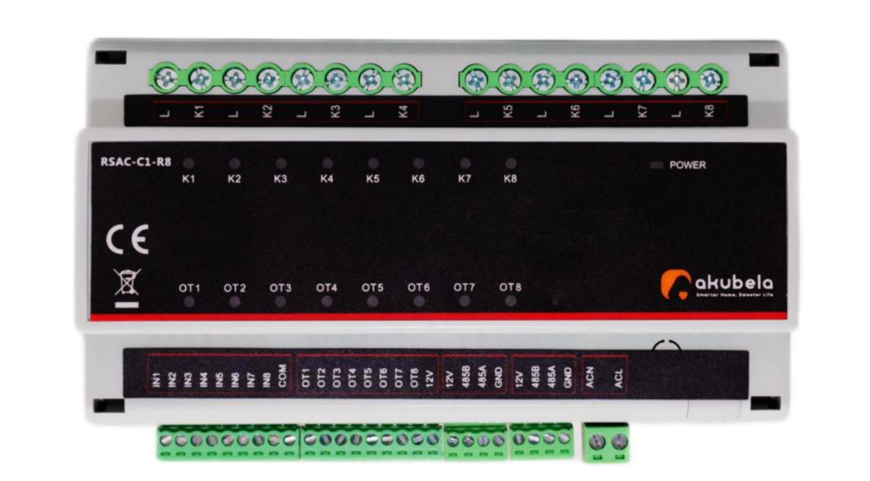
RSAC-C1-R8
Before getting started
Cut off the circuit power before starting the wiring!
Ensure your computer is on the same network as the HyPanel device. This allows you to access the device's web portal for configuration.
HyPanels with RS485 terminals support RS485 switch actuator configuration starting from these firmware versions:
HyPanel: 51.1.36.108
HyPanel Lite: 41.1.35.45
NOTE:
HyPanel Lite does not support RS485 switch actuator configuration when used as the home center.
HyPanel Plus: 52.1.36.214
HyPanel Pro: 71.1.38.111
HyPanel Ultra: 281.1.38.112
HyPanel Supreme: 1001.1.38.112
SmartPanel: 933.1.38.408
SmartPanle Elite 10: 119.1.38.407
Wiring
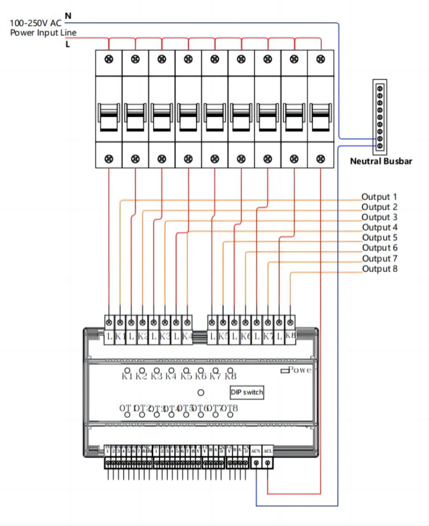
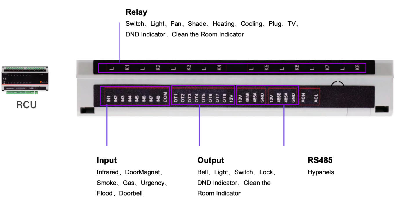
Zone | Port | Wiring Instructions | Remark |
ACL, ACN | Connect to 100-250VAC Line wire & Neutral wire | For zero crossing detection | |
RS485 | GND, 12V | Connect to the 12V/2A power adapter | Provide power to the switch actuator |
485A, 485B | Connect to RS485 devices | ||
Output | OT1 ~ OT8 | Connect to the negative wire of the output devices | |
12V | Connect to the positive wire of the output devices | ||
Input | IN1 ~ IN8 | Connect to one wire of the input devices | |
COM | Connect to the other wire of the input devices | ||
Relay | K1 ~ K8 | Connect to the load devices | |
L | Connect to 100-250VAC Line wire |
Configuration
1. Enable RS485 configuration function
(1) Log into the HyPanel’s device web portal using the device’s IP address.
TIP:
For detailed instructions on login to the device web portal, please refer to this guide.
(2) Go to Device > RS485 Configuration.
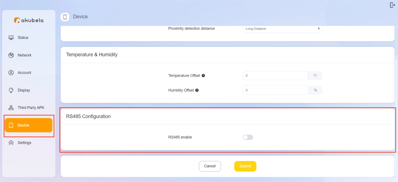
(3) Activate the RS485 function, and set the Connection Type to “akubela” for switch actuator connections.
TIP:
For standard RS485 connections, use the default value “RTU”.
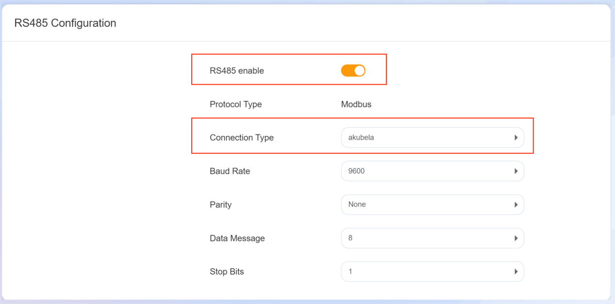
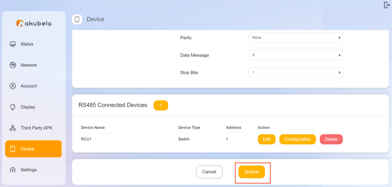
(4) (Optional) Configure the parameters if needed:
Baud Rate: Set the data transmission speed based on your requirements.
Parity: Choose the error checking method.
Data Bits: Select the number of data bits in a byte.
Stop Bits: Set the number of stop bits.
2. Add the switch actuator
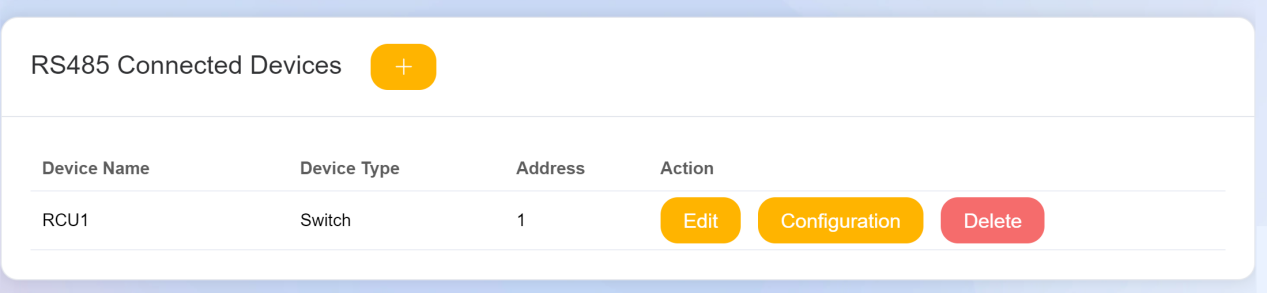
(1) Scroll down to the RS485 Connected Devices field.
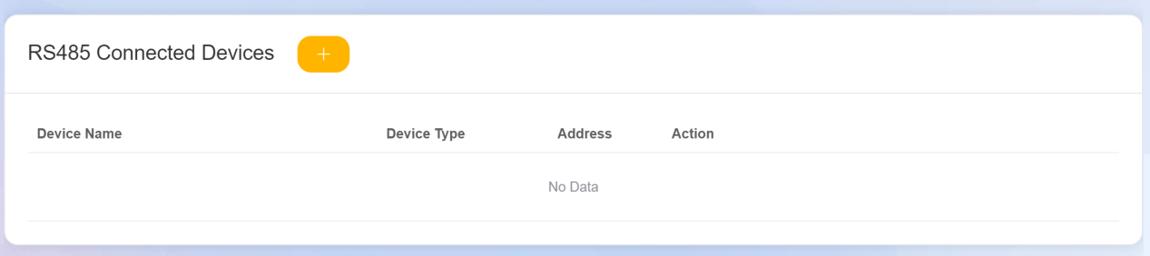
(2) Click ![]() and configure the following settings.
and configure the following settings.
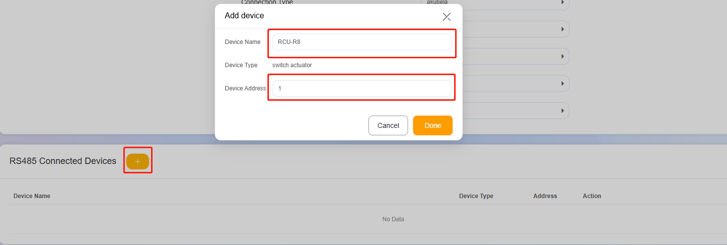
Device Name: Assign a custom name for the device.
Device Address:
a. Toggle on the desired DIP switch(es) on the physical device.
b. Enter the corresponding number (1-63) based on the toggled DIP switch(es).
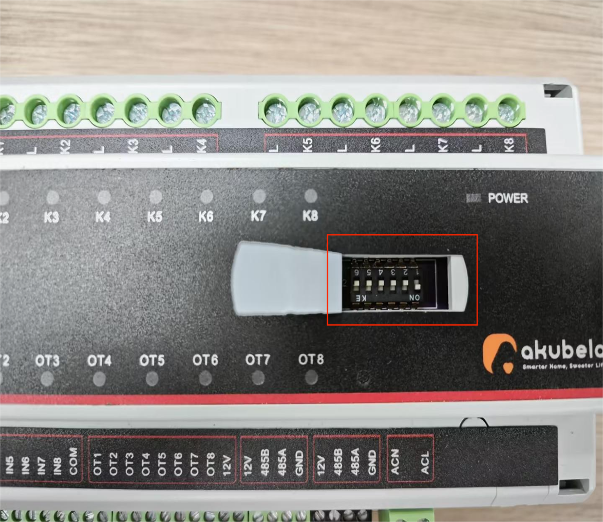
NOTE:
The address mapping is as follows:
Switch Number
Address
1
1
2
2
3
4
4
8
5
16
6
32
Example:
When you toggle on Switch No. 1, enter 1 in the device address box.
When you toggle on Switches No. 1, 2, and 3, add their values (1 + 2 + 4) and enter 7 as the device address.
(3) Click Done. The added actuator is displayed.
3. Configure connected devices
(1) Click  to open the device setting window.
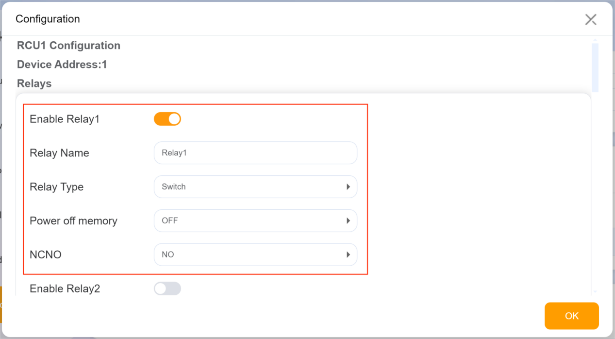
Configure Relays
① Enable the desired relay.
② Name the relay if needed.
③ Set the following parameters based on the relay.
Relay Type: Select the desired relay type (e.g., Switch, Light, Fan).
Power off memory: Select whether to maintain the relay's state after a power outage.
NCNO (Normally Closed or Normally Open): Specify the relay’s behavior based on its wiring configuration.
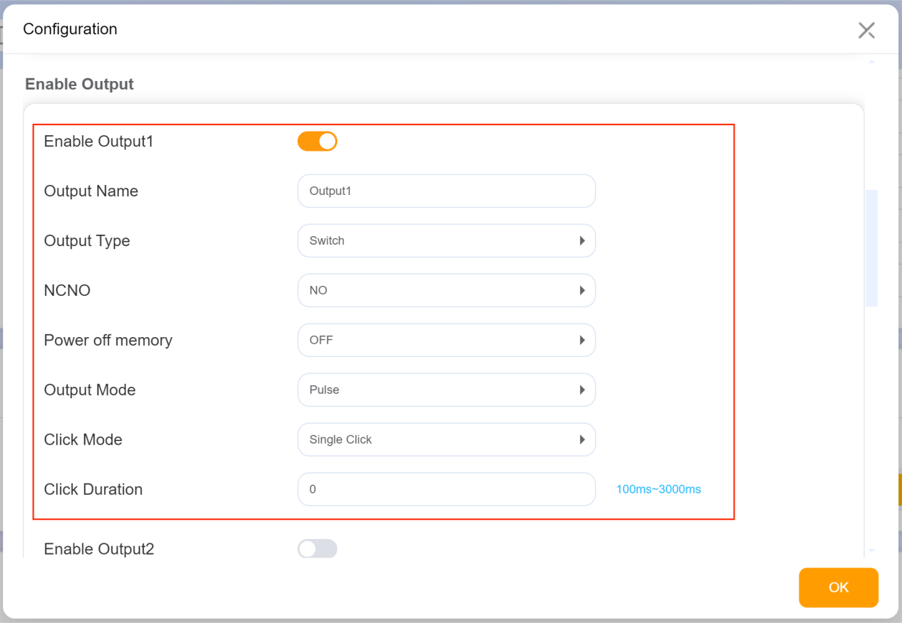
Configure Digital Outputs
① Enable the desired output.
② Name the output if needed.
③ Set the following parameters based on the output.
Output Type: Choose the output type (e.g., Lock, Bell, DND indicator).
NCNO: Select the output behavior.
Power off memory: Set the power off memory behavior.
Output Mode: Choose the output mode (High and Low Level or Pulse). If "Pulse" is selected, you can also set the click mode and click duration.
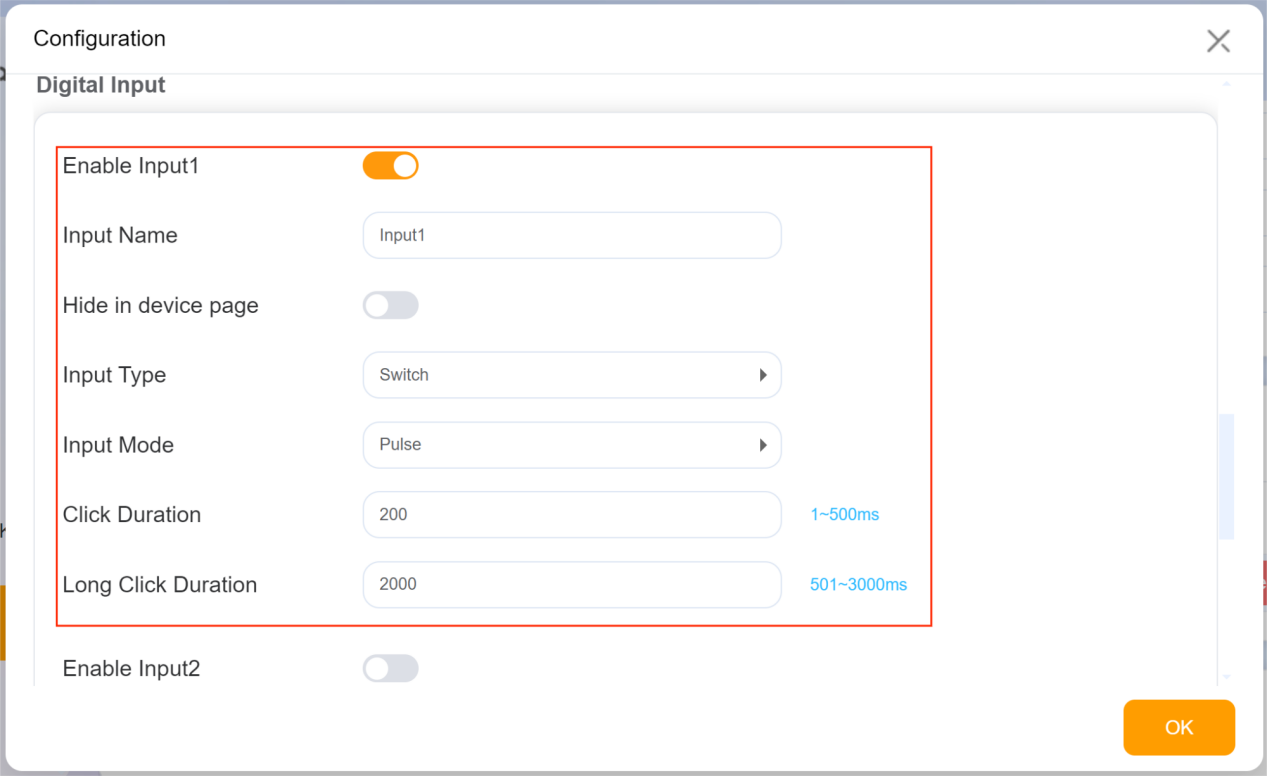
Configure Digital Inputs
① Enable the desired input.
② Name the input if needed.
③ Specify whether to hide the input on the HyPanel’s screen.
④ Select the input type (e.g., DoorMagnet, Gas, Urgency).
⑤ Choose the input mode (High and Low Level or Pulse). If "Pulse" is selected, you can set the click duration.
(2)Click ![]() to save the device settings.
to save the device settings.
4. Save all settings
Once you've completed all the above settings, click ![]() at the bottom of the page to validate your changes.
at the bottom of the page to validate your changes.
Upon completion, the configured device (e.g., Relay 1) will be visible on the HyPanel.
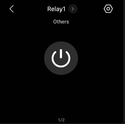
Activating this relay will turn the corresponding indicator on the switch actuator.
