About This Manual
Thank you for reading this manual. It is designed for administrators managing the SDMC (SIP Device Management Center) for integrated control of personnel (residents, property managers), network settings, intercoms, messages, devices, access control, authentication methods, logs, lift control, and monitoring. This manual applies to SDMS version 6.0.0.75.
Please click here for the latest software version.
What’s New in Version 6.0.0.75:
Support setting whether to display door phone on the indoor monitor’s Monitor and Contacts list.
Support entering the Zone Type when configuring AutoP for indoor monitors.
SDMC Overview
SDMC (SIP Device Management Center) is generally installed in the community management center. The software serves as a LAN-based on-premise platform designed to manage the personnel, devices, access control, intercom, alarm, message, lift control, video monitoring, etc at one stop.
Users using SDMC will be able to:
To achieve data synchronization between the SDMC and the device.
To manage the residents, property staff, and access control with various types of authentication methods.
To manage the deployment of devices on a node basis for residents.
To make IP/SIP call the intercom devices, and monitor community-wide surroundings for security purposes.
To manage various types of logs.
To manage and deal with alarms.
To manage messaging and advertisement pushing.
To import and export system data and database for the convenience of data sharing and system configuration.
To manage the lift control.
SDMC Installation
Installation Requirements
Prior to the installation of the SDMC software, make sure that the following installation requirements are met:
Windows 7 operating system or above.
No SDMC and SDMC software are installed on your personal computer or on other personal computers in the same network.
The Firewall on your computer is turned off.
Install SDMC
Steps to install SDMC.
Decompress the SDMC zip file
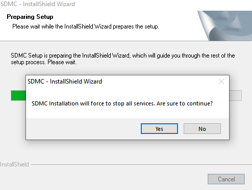
Click the setup.exe file.
Click “Yes” in the pop-up window to continue the installation.
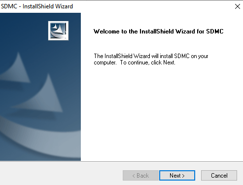
4. Click Next to go to the next step.
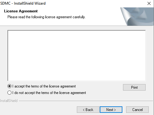
5. Accept the terms and click Next to the next step.
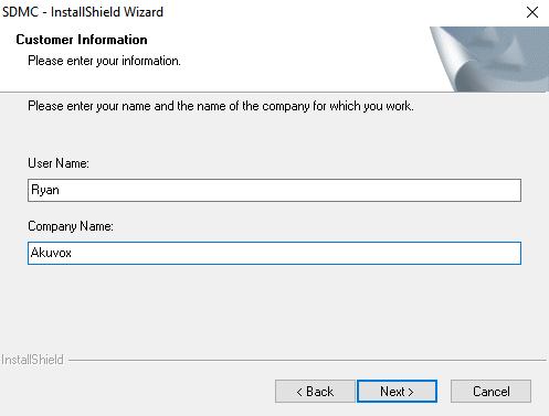
6. Enter the User Name and Company Name and click Next.
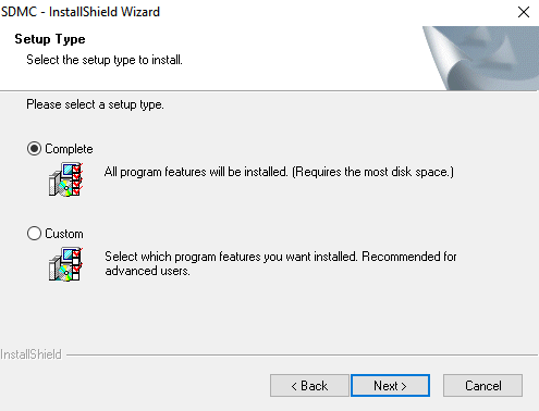
7. Select the installation path by default or the other path to your preference and click Next.
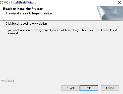
8. Click Install to finish the installation.
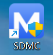
After the installation is completed, you will see the SDMC icon along with the SDMC ServerManage icon on your desktop.
Note
The SDMC installation path should not contain any Chinese characters.
Set up SDMC Server Manage Software
SDMC ServerManage is a program that is installed along with the SDMC. The software is designed to manage services called SDMC Service and WatchdogService.
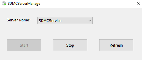
SDMC Service: This service is used to facilitate two-way communication between the SDMC and the devices for data transmission. Therefore, the service must be turned on to ensure the smooth running of SDMC.
WatchdogService: Upon installation, Watchdog automatically initiates and continuously monitors the status of SDMCService. Specifically, if SDMCService is found inactive, Watchdog will automatically reactivate it. This ensures that SDMCService is always operational as long as Watchdog is active.
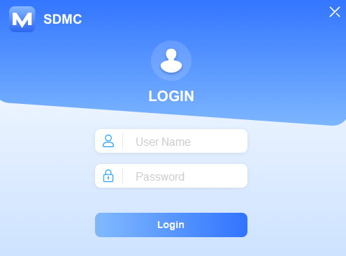
Log in to SDMC
To log in to SDMC for the first time, enter the username and password. Both are admin by default. You can click  on the upper-right corner of the screen to close SDMC.
Getting Started
Network Connection
You need to select a specific Network Interface Card (NIC) used to connect SDMC and devices for data transmission. The SDMC IP address will appear automatically after you select your NIC.
1. Click to select NIC.
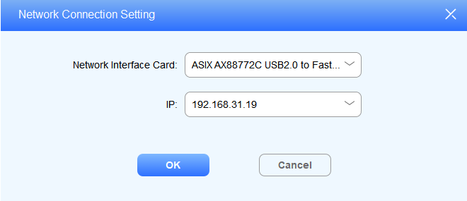
2. You can also click 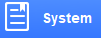 ,select System Settings> Network to set and edit the network connection after login.
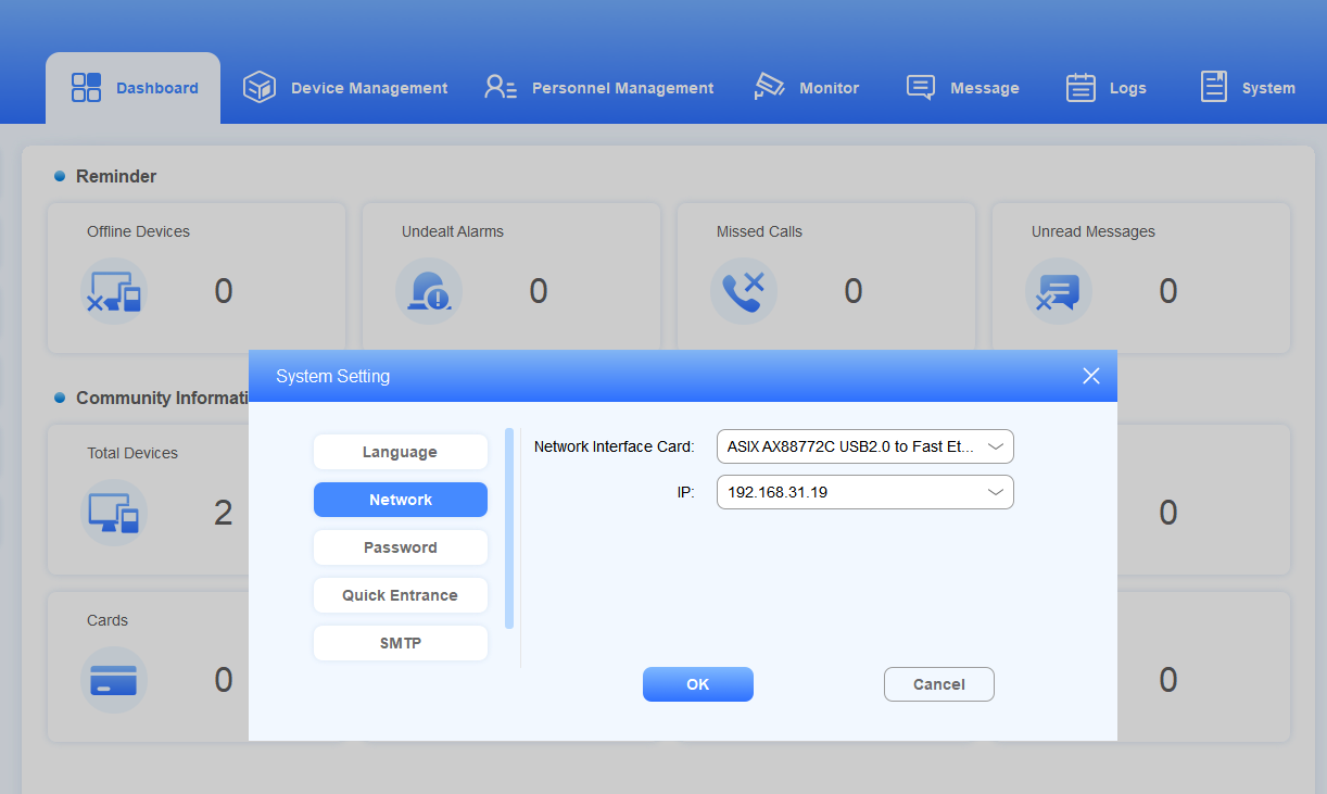
Language
SDMC currently supports English and Chinese languages (both simplified and traditional Chinese).
Click System > System Settings> Language.
Click OK for the confirmation.
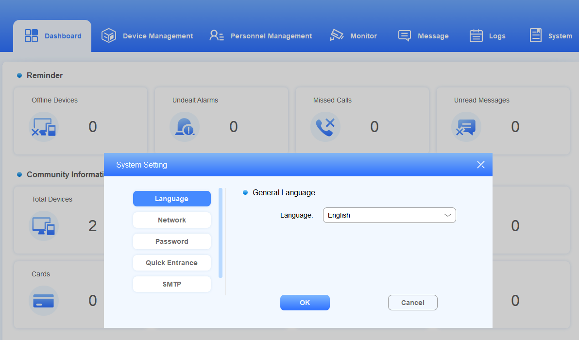
Password
After you log in to the SDMC, you can change the SDMC login password by going to System > System Settings > Password.
Dashboard
SDMC dashboard mainly consists of seven modules, namely Dashboard, Device Management, Personnel Management, Monitor, Message, Logs, and System, along with two functional columns on both sides.
.png)
Modules
Modules | Descriptions |
Dashboard | Gives you a quick view of real-time statistical information on devices, calls, messages, residents, and access logs, etc. |
Device Management | Allows you to create nodes and manage devices by adding, editing, or deleting them. You can adjust device settings before syncing the changes. You can make calls to a specific device and open the door. |
Personnel Management | Allows you to manage access control for the residents and property management, to manage various types of access authentication methods for staff, residents, and visitors, etc. |
Monitor | Allows you to manage monitoring devices in terms of adding, editing, and deleting monitoring devices, and performing video preview for monitoring. |
Message | Allows you to manage messages and notification ads, etc. |
Logs | Allows you to manage various types of logs, such as access logs, alarm logs, call logs, and system logs. |
System | Allows you to manage SDMC SIP settings, Autop data backup, lift control, network, language, password, dashboard operation icons on the left column, SMTP, and device reset and reboot. |
Device Management
The Device Management module allows you to manage device deployment on a node-by-node basis and synchronize data to the corresponding devices at selected nodes. It also enables you to make calls to specific devices and open doors. In addition, you can search and check data for specific device(s).
Introduction to Nodes
Create nodes before deploying the devices to the nodes. You can either manage the node one by one or use a template.
About Nodes
Node | Descriptions |
Community | Community is the root nodes which is extendable to the other five subordinate nodes: Public/Building > Unit > Floor > Room. Public and Building are parallel nodes. |
Public | Public is the second-level node. You can create 1-99 public nodes. |
Building | Building is also the second-level node, which can be extended to the other three subordinate nodes: Unit >Floor > Room. You can create 1-999 building nodes. |
Unit | Unit is the third-level node, which can be extended to the other two subordinate nodes: Floor > Room. You can create 1-99 unit nodes. |
Floor | Floor is the fourth-level node, which can be extended to Room node. You can create 1-99 unit nodes. |
Room | Room is the lowest-level node. You can create 1-99 room nodes. |
Add Nodes
Add Nodes Separately
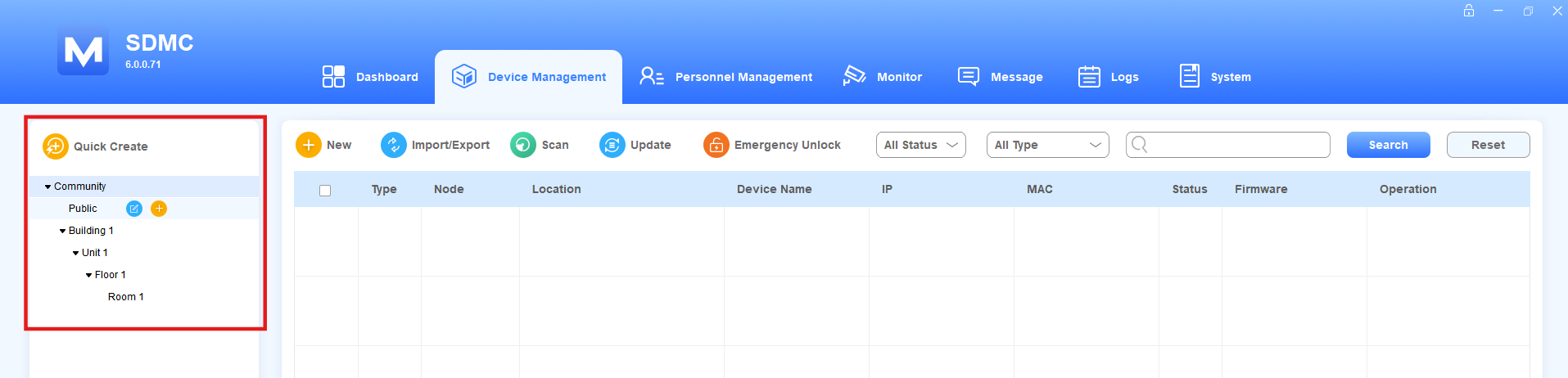
In the Device Management module, you can create nodes from the community node to the room node.
Move the arrow to the Community (root node), and click
 to create building nodes.
After the building nodes are created, you can create other nodes subordinated to the building nodes in the same way.
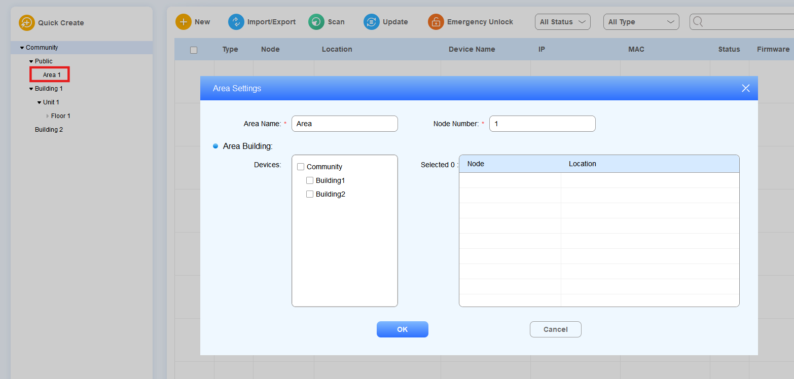
Move the arrow to the Public node and click
 to create a public area node.
Note
You can click
to change the node name.
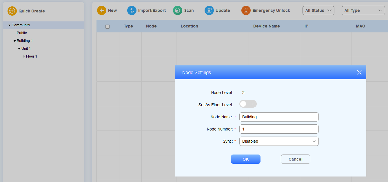
Add Nodes Using a Template
Click
 to go to the node template.
Set up the node number at each node level.
Create From: This decides the order of the created node. For example, if you want to create Buildings 10-20 and there are already Buildings 1-12, you can enter 9 in the Create From field, and the new buildings created will be ordered from 10. The original Buildings 10, 11, and 12 will be reordered to be Buildings 21, 22, and 23.
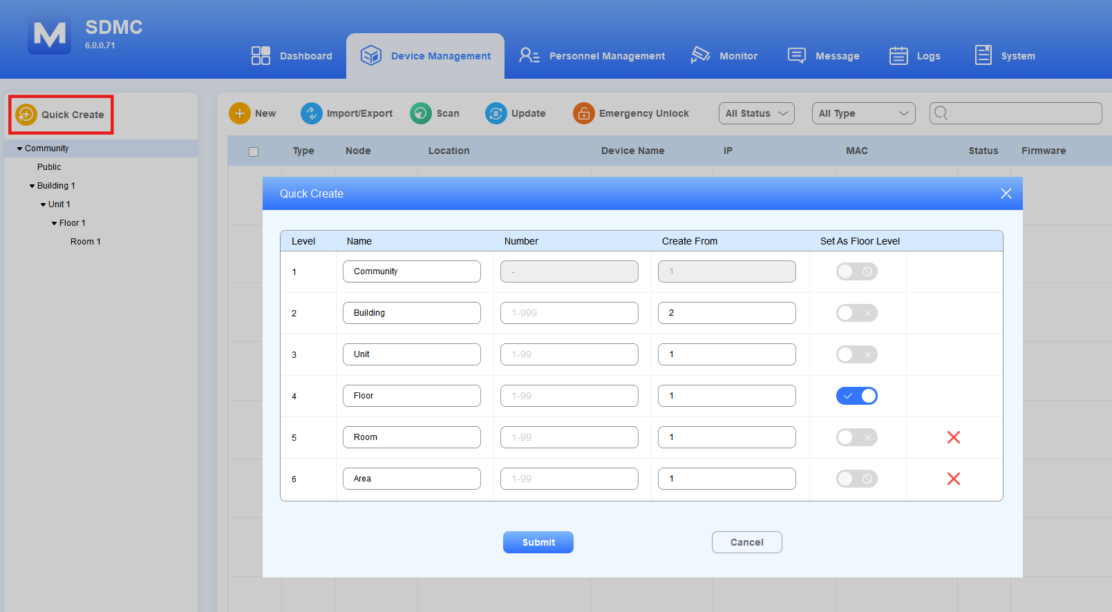
Set As Floor Level: Decide the accessible floors for residents. The node number equals the floor number. For example, if you enable Set As Floor Level for the unit with node number 6, the resident can access the 6th floor. You can also turn on or off the feature when editing nodes.
Note
Room and public nodes are optional.
Set As Floor Level is enabled for Level 4 by default.
Set As Floor Level can only be enabled for Level 2, 3, 4, or 5. The accessible floors will be synchronized to the Personnel Management > Resident > Add Resident interface.
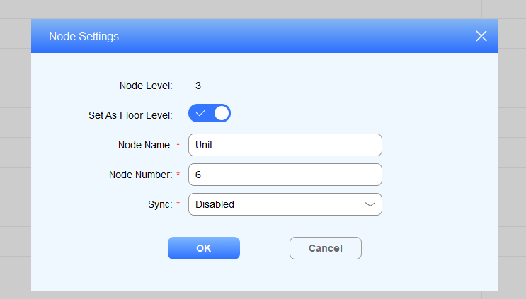
Edit/Delete Nodes
You can edit node names and numbers and delete them.
Click
 of the desired node.
Change the node name and number.
Enable or disable Set As Floor Level.
Select Enabled in the Sync field if you want all the parallel nodes have the same name at the same node level. For example, if you change building 1 to building A, then all the building nodes will be renamed to building A after synchronization.
Click
 to delete the node.
Building Node
Public Node
Add Devices
After the nodes are created, you can start adding the device(s) to the specific level of nodes in the Device Management module. Devices can be added separately, in batches, or via scanning.
Add Devices Separately
In the Device Management module, click
 .
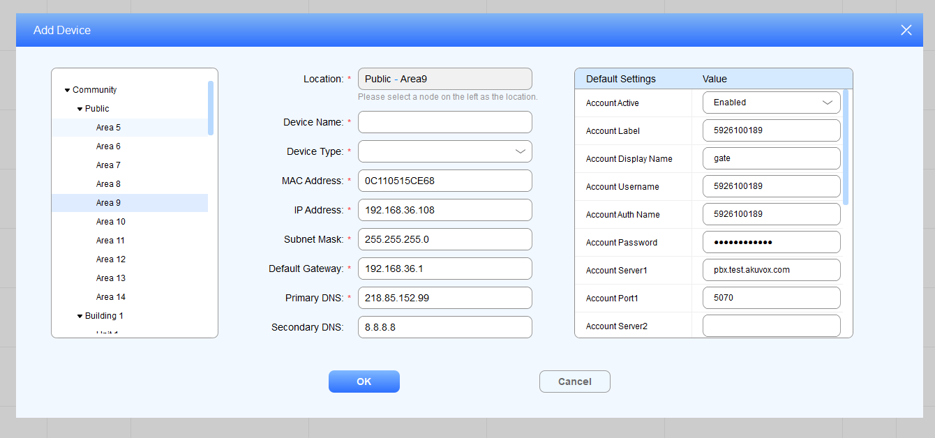
.Select the desired node to add the device.
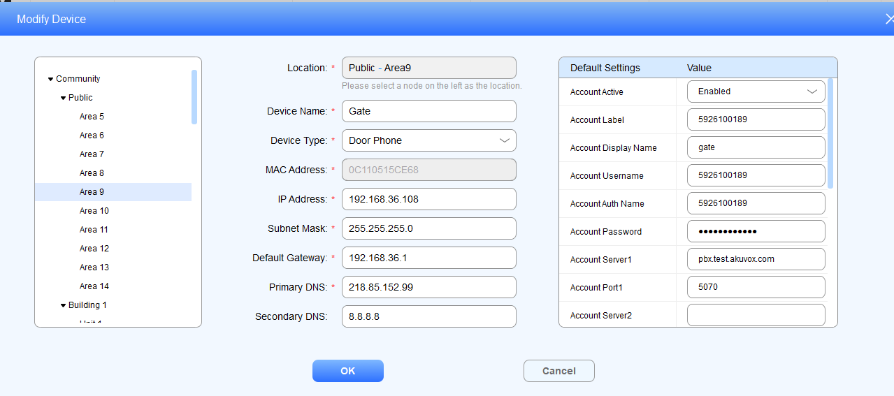
Fill in the device name, type, and network parameters.
Configure and synchronize the device settings to the device if needed.
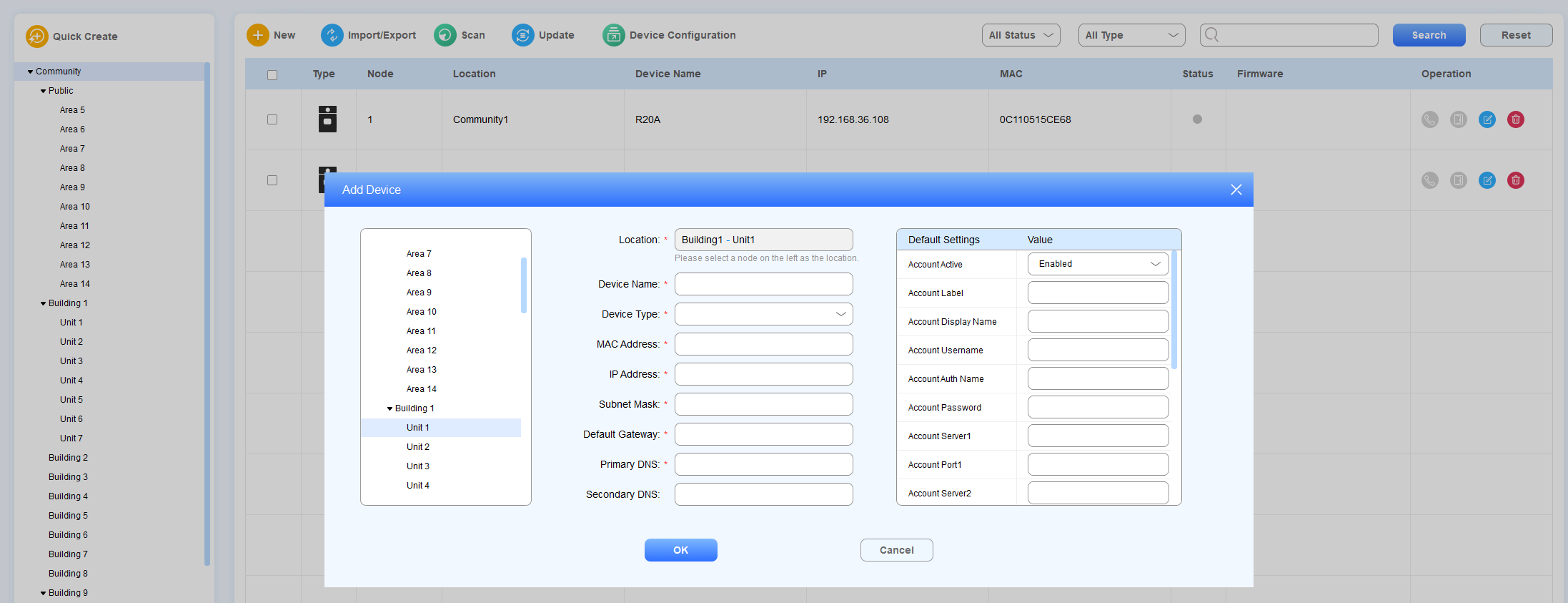
Parameter Description:
Parameter | Description |
Location | Select the node as the location in the left column. |
Device Name | Name the device to distinguish it from others. The maximum field length is 63 digits. If you leave the device name blank, the system will prompt “Please enter the name”. |
Device Type | Select device type: Indoor Monitor, Door Phone, Guard Phone, and Access control. The default device type is Door Phone. |
Show Monitor on Indoor Monitor | Available when the Device Type is Door Phone. Set whether to display the door phone in indoor monitor’s Monitor list. |
Show Contacts on Indoor Monitor | Available when the Device Type is Door Phone. Set whether to display the door phone in indoor monitor’s Contacts list. |
MAC address | Fill in the device MAC address. |
IP Address | Fill in the device IP address. |
Subnet Mask | Fill in the device subnet mask. |
Default Gateway | Fill in the device default gateway. |
Primary DNS | Fill in the primary DNS. |
Secondary DNS | Fill in the secondary DNS. |
Default Settings
Settings | Description |
Account Active | Enable or disable the device SIP account. |
Account Label | Fill in the device SIP account display label. |
Account Display Name | Fill in the device SIP account display name to be shown on the device being called. |
Account Username | Fill in the device SIP account username, which can be the same as the SIP account authentication name. |
Account Auth Name | Fill in the device SIP account authentication name. |
Account Password | Fill in the device SIP account authentication password. |
Account Server1/2 | Fill in the SIP server IP address. |
Account Port1/2 | Fill in the SIP server port for the data transmission. The default SIP server port is 5060. |
RTSP Enable | Enable the RTSP if you want to obtain the video footage from the device. |
Prevent SIP Hacking | Enable it if you want to deny the call from other devices that do not share the same SIP server as the called-party device. |
DTMF Option | Select the number of DTMF digits for the door access control (Ranging from 1 to 4 digits). |
DTMF Code 1/2/3 | Set the three sets of DTMF codes for relay A/B/C and the number of the codes. |
Relay Enable | Enable the open relay via the HTTP function. |
Relay Username | Create an authentication name for the open relay via HTTP. Relay username must be configured before you can open the door via HTTP on SDMC. |
Relay Password | Create a password for the open via HTTP authentication. The relay password must be set before you can open the door via HTTP on SDMC. |
Default Settings for MR01:
Settings | Description |
|---|---|
Installation Method | Specify how the device is mounted, which affects coordinate ranges and height constraints.
|
xMin | The minimum x-coordinate centered around MR01(-3000 to 0). |
xMax | The maximum x-coordinate centered around MR01(0 to 3000). |
yMin | The minimum y-coordinate centered around MR01. |
yMax | The maximum y-coordinate centered around MR01(0 to 3000). |
zMax | The height of the detection space. |
Installation Height | The installation height of MR01. |
Installation Location | The installation location of MR01. |
Add Devices in Batch
SDMC allows you to add devices in batch using an .xlsx file. You can export existing device information and use the file as a template.
1. In the Device Management module, click  .
.
2. Click Export to export the template file.
3. Follow the instructions and enter the device information.
4. Click Import to upload the modified file.
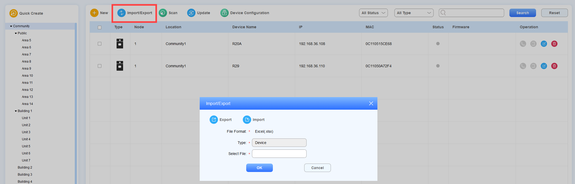
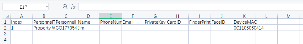
Sample Template: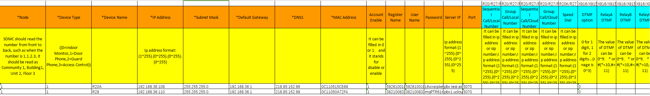
Note
You can import a maximum of 20000 devices at a time.
Without using a USB license, when the number of devices already added plus the devices listed in the file exceeds 500, the file cannot be imported.
Add Devices via Scanning
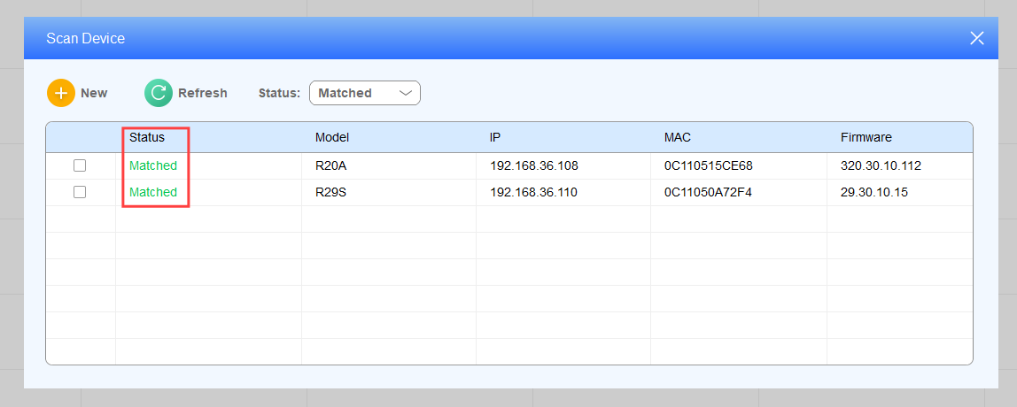
SDMC allows you to scan the devices in the same network before adding them to the specific node. Device network information will be automatically filled in.
1. In the Device Management module, click Scan. Select to display Unmatched, Matched, or All devices in the Status field.
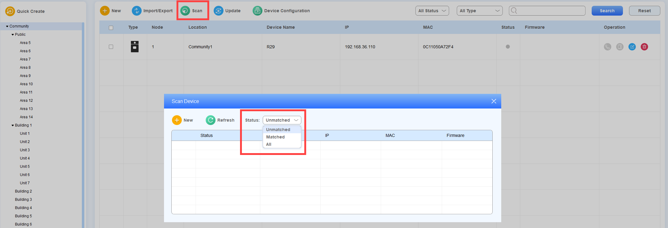
2. Tick the checkbox of the desired device, and click
 .
.
3. Select the desired node and complete the settings.
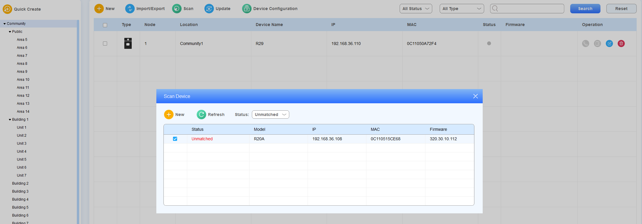
After the devices are added successfully, the status will change from unmatched to matched.
Check/Edit/Delete Device
Search for and check the device by its online status, type, or keyword.
Click
 to delete the desired device.
Click
 to edit the desired device.
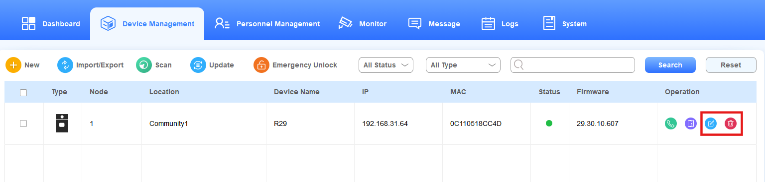
Edit the device in terms of moving the device to a different node and modifying its network and default settings.
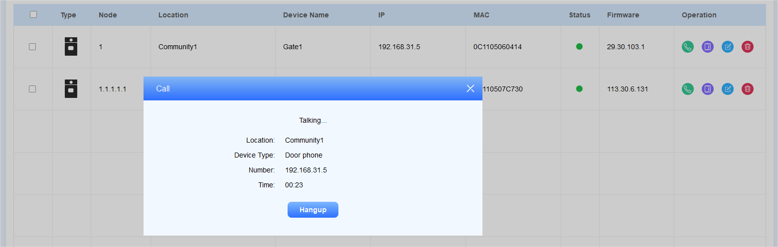
Make Calls to Device
As an administrator, you can make call to the specific device if needed.
Click
 of the specific device.
Click
 to hang up the call.
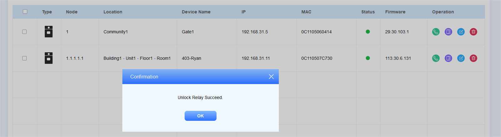
Trigger Device Relay via HTTP
Click
 of the specific device.
Devices AutoP
SDMC allows you to perform device autop in batch.
Manual Input
You can manually input the AutoP commands.
1. Click Device Management > Device Configuration >  > Manual Input Mode.
2. Enter the AutoP command. Enter multiple commands on newlines with a maximum of 4096 bytes.
3. You can tick the box of the device type(All, Indoor Monitor, Door Phone, Guard Phone, Access Control) or nodes to quickly select desired devices. You can also enter the device name, IP, or MAC to search.
4. Click Submit to save the configuration.
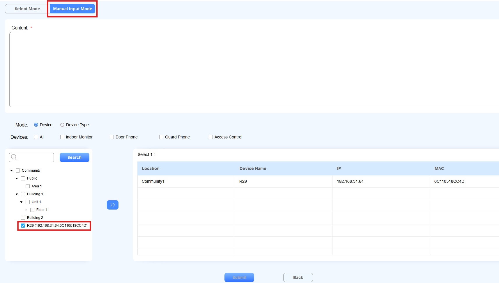
After creating commands, you can search for, edit, and delete them on the Device Configuration window.
Select Commands
You can select commands by choosing their device type and specific category.
Click Device Management > Device Configuration >
.
Choose Select Mode, the device type(indoor monitor, guard phone, or door phone), and the feature category.
Check the desired commands.
Check the desired device(s) by selecting their location.
Submit the setting.
Upgrade Firmware
SDMC allows you to upgrade device firmware remotely.
1. Click Device Management > Upgrade Management > .
2. Select the device model in the upper left corner and tick the box of the desired device.
3. Select Upgrade Right Now or customize the time by clicking Idle-time Upgrade.
4. Click Select File to upload the firmware and click Upgrade.
You can select the device model or status type (All Status, Finished, Processing, and Cancel) to check the device upgrading details.

Personnel Management
Personnel Management module includes three sub-modules: Resident, Property Worker, and Verification Mode, where you can manage residents, property staff, various types of authentication, and access control.
Manage Residents
You can assign residents to rooms and buildings, etc, manage their personal information, and grant them various access methods.
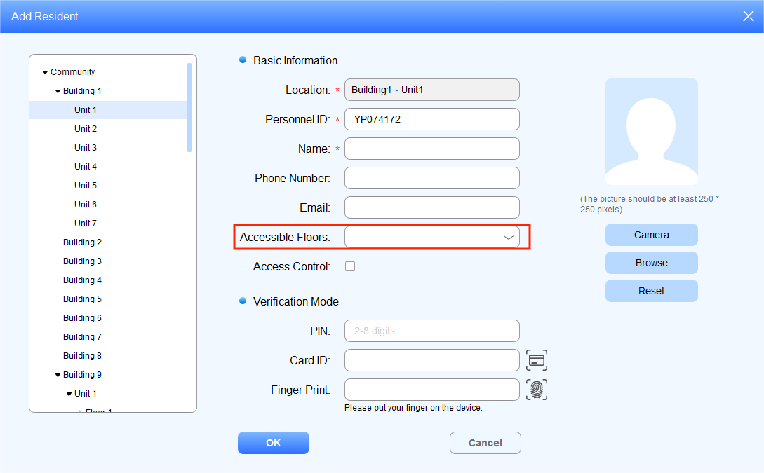
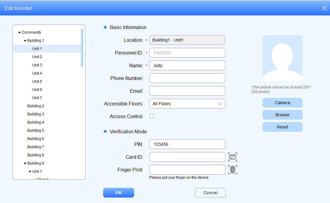
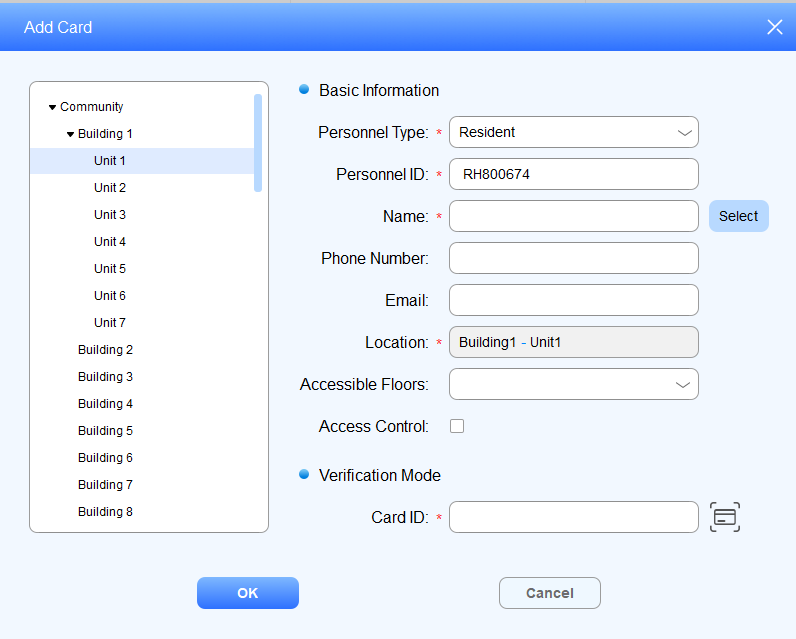
Add Residents
You can add residents to the rooms and buildings on a node basis.
Click Personnel Management > Resident, then click
 .
.Select the desired room node to add the resident.
Enter the resident’s information.
Select the floor number that the resident is allowed to access.
You can tick the box of Access Control to set the period when the user is allowed to open doors. It is disabled by default.
Set access authentication methods for the resident:
Create the private PIN code.
Click
 to obtain the ID card number from the card reader connected to the SDMC, or enter the ID card number directly.
Click
 to obtain the fingerprint from the fingerprint reader connected to the SDMC.
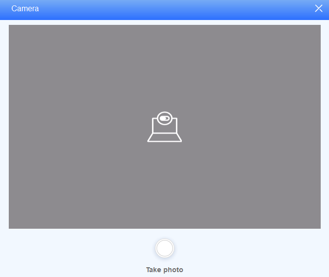
Upload Resident Face ID for access authentication.
a. Click Browse to upload the resident’s picture, and reset the picture for re-upload if needed.
b. Click Camera to take a picture of the resident before uploading.
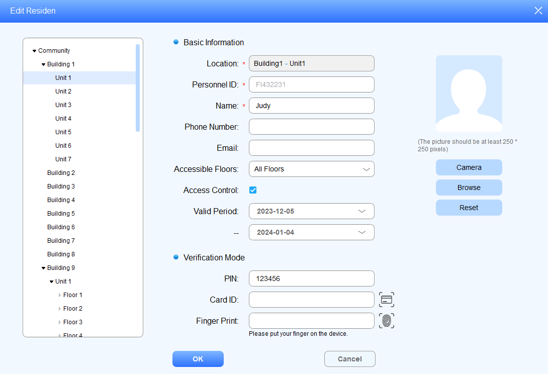
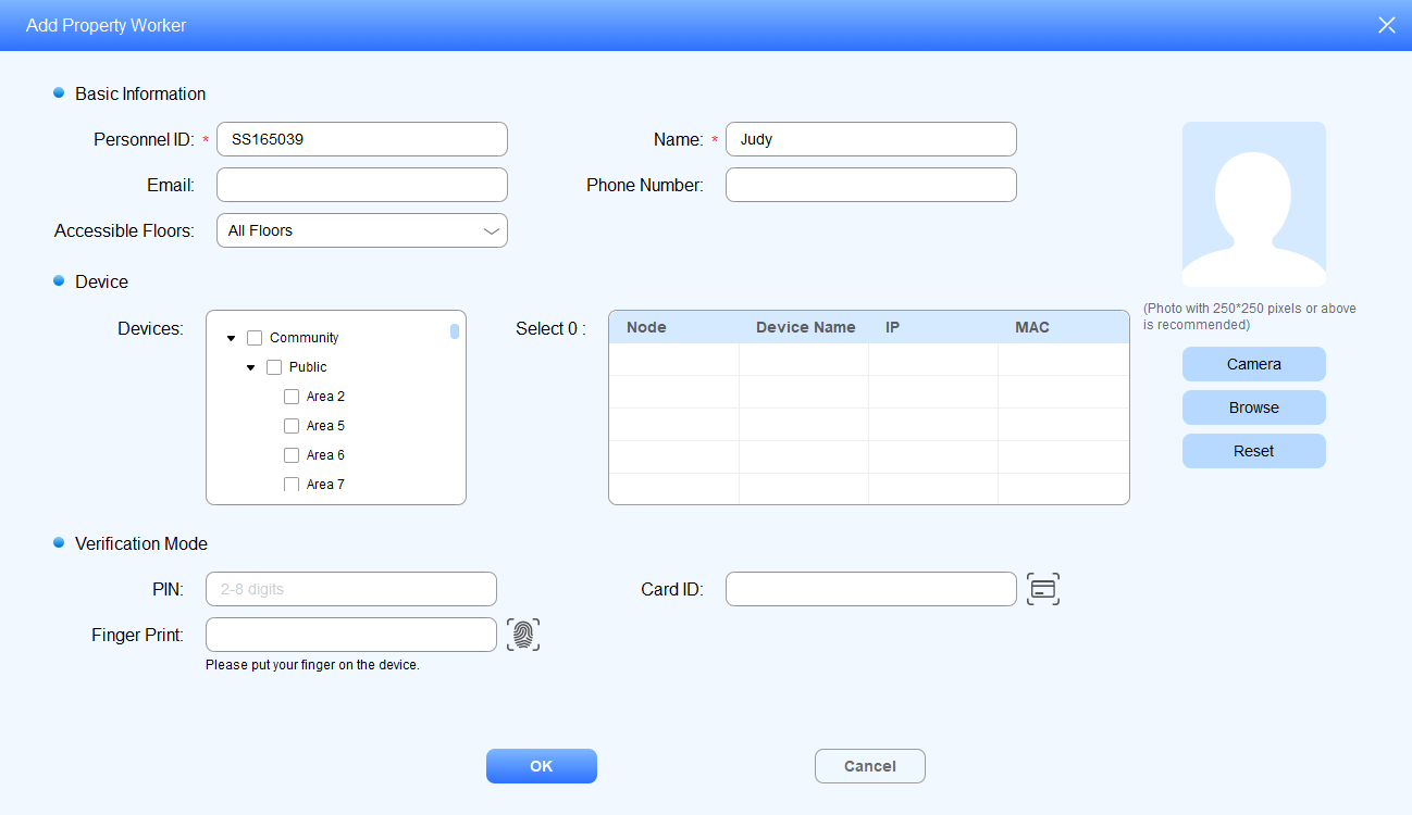
Field Name Description:
Field Name | Description |
Location | Location can only be the room node (the lowest node). |
Personnel ID | Personnel ID can be automatically generated, or you can change the personnel ID when adding the resident. |
Name | 63 characters maximum in length. |
Phone | 63 characters maximum in length. |
63 characters maximum in length. | |
Accessible Floors | You can select up to 10 floor numbers. When All Floors is selected, other options cannot be selected. |
Access Control | Enable the feature to set the time when the user can open doors. |
Valid Period | Select the valid time span for access control methods. |
Private Key | Private PIN code should be 2-8 digits |
Card ID | You can only enter number or alphabet with 127 digits in length. Each resident can be assigned with five card numbers maximum. And card numbers should be separated by “;”. |
Finger Print | Scan your finger on the fingerprint reader. |
Face ID | You can upload the face ID directly, or you can take a picture of the resident with your PC camera (the picture should be 480*480 or greater). Face in the picture should be clear and in front-view, accounting for 1/4 of the total space of the picture. |
Note
After the resident information and authentication methods are set up, you are required to click
in the Device Management Module to synchronize the data to the device.
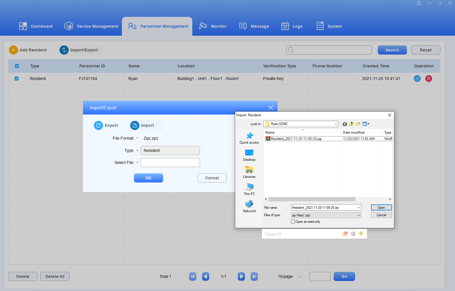
Import/Export Resident Data
You can import the .zip file to SDMC to quickly set up the resident’s information and access authentication methods, and export the .zip file for backup.
Click
 .
.Click Import, and select the .zip file in your local PC, then upload the file to your SDMC.
Tick the checkbox of the specific resident(s) or tick
 of all the resident, then click Export and select where you want to store the .zip file in your PC, then click Save.
.Zip file sample


Note
You are allowed to upload the .xlsx excel file to the SDMC directly if you do not need to import face and finger print data.
Check/Edit/Delete Residents
You can search, check, edit, and delete the residents that have been added.
Search the resident by Personnel ID, Name, Location, Phone Number in the Fuzzy search field
Tick the checkbox of the specific resident(s) or tick the
 if you want to delete all the residents.
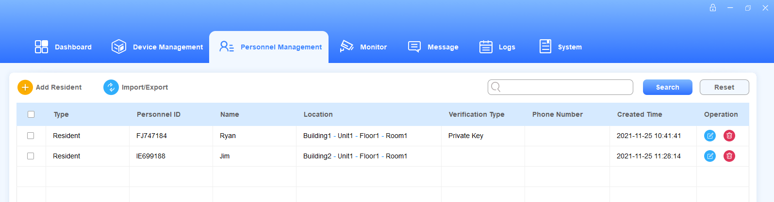
3. Click  of the desired resident to edit.
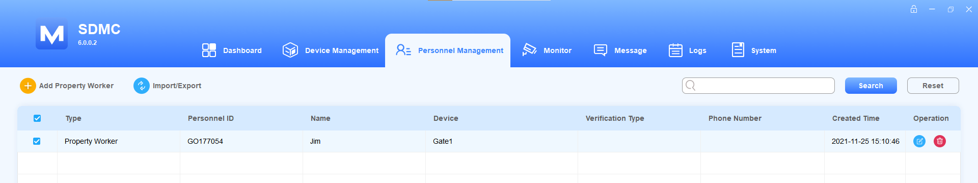
Manage Property Staff
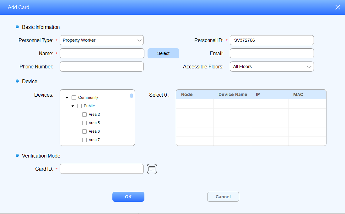
Add Property Staff
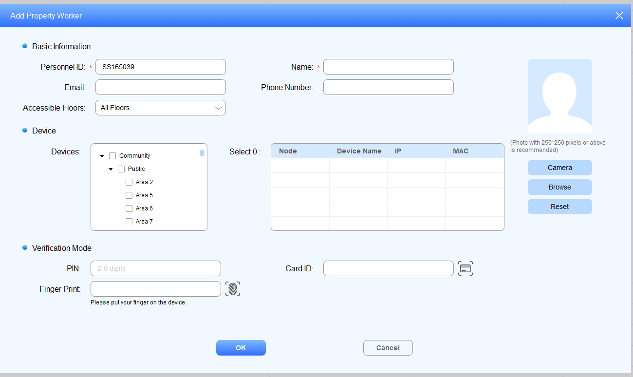
You can add property staff(s) and grant them the permission to open doors in the specific location for the property management.
Click Personnel Management > Property Worker >
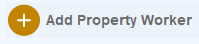 .
.Enter the staff’s personal information and change the automatically generated personnel ID if needed.
Allow staff to access a specific door by choosing an access control device at the desired location.
Set the verification mode for the staff in the same way as you do for residents.
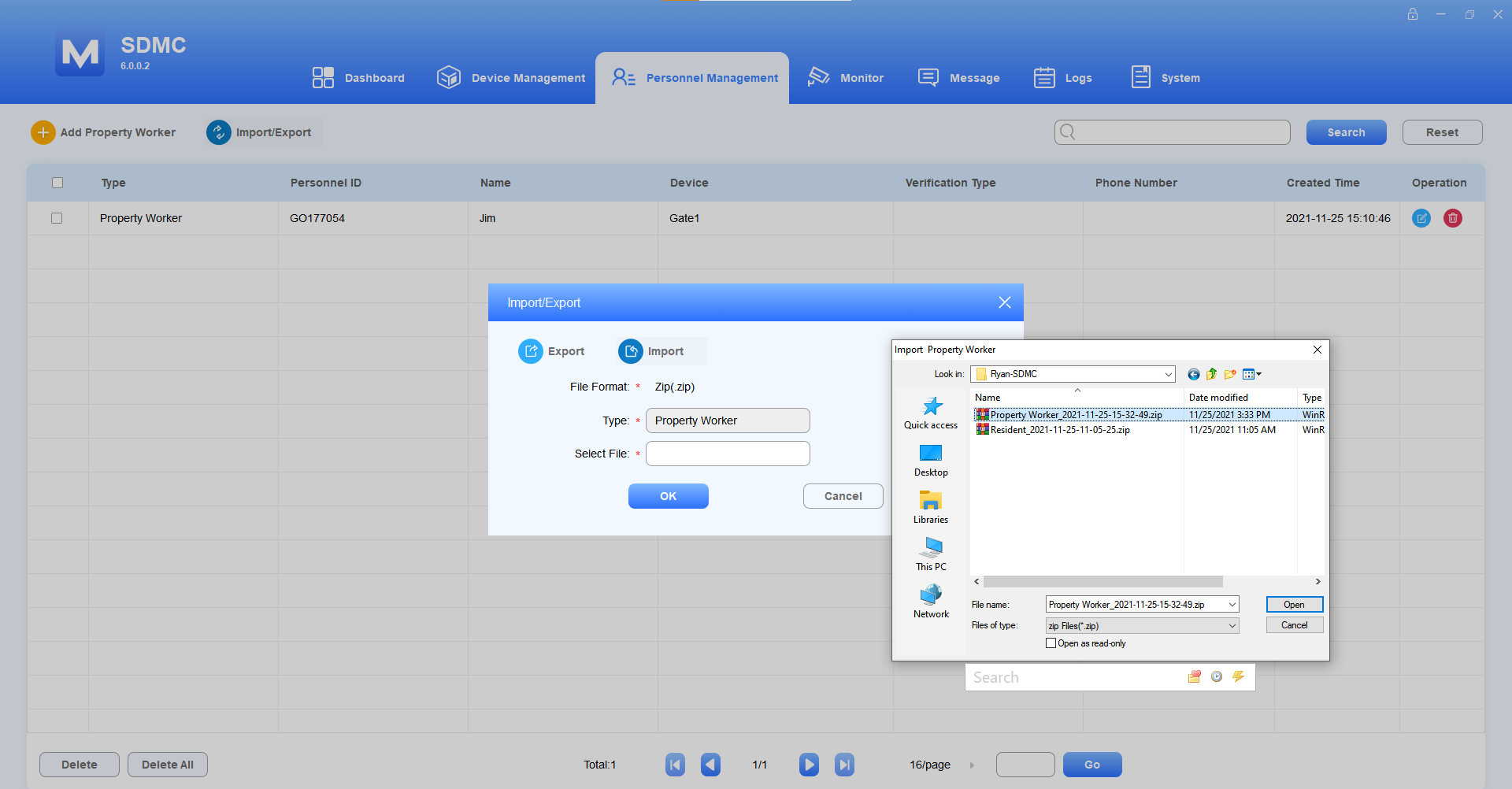
Import/Export Property Staff
You can import the .zip file to SDMC to quickly set up property staff information and access authentication methods, and export the zip file as needed for backup.
Click
 .
.Click Import, and select the .zip file in your local PC, then upload the file to your SDMC.
Tick the checkbox of the specific property staff(s) or tick
 of all the staffs, then click Export and select where you want to store the .zip file in your PC, then click Save.
.Zip file sample

Note
You are allowed to upload .xlsx excel file to the SDMC directly if you do not need to import face and finger print data.
Check/Edit/Delete Property Staff
You can search, check, edit, and delete the property staff that have been added.
Search the property staff by Personnel ID, Name, Location, Phone Number in the Fuzzy search field.
Tick the checkbox of the desired property staff(s) or tick
 if you want to delete all the property staff.
3. Click of the desired user to edit.
Note
Keywords used for searching property staff are case-sensitive.
Access Authentication Management
You can set up different access methods for both residents and property staff and specify the locations they are allowed to access.
Face ID
Create Face ID
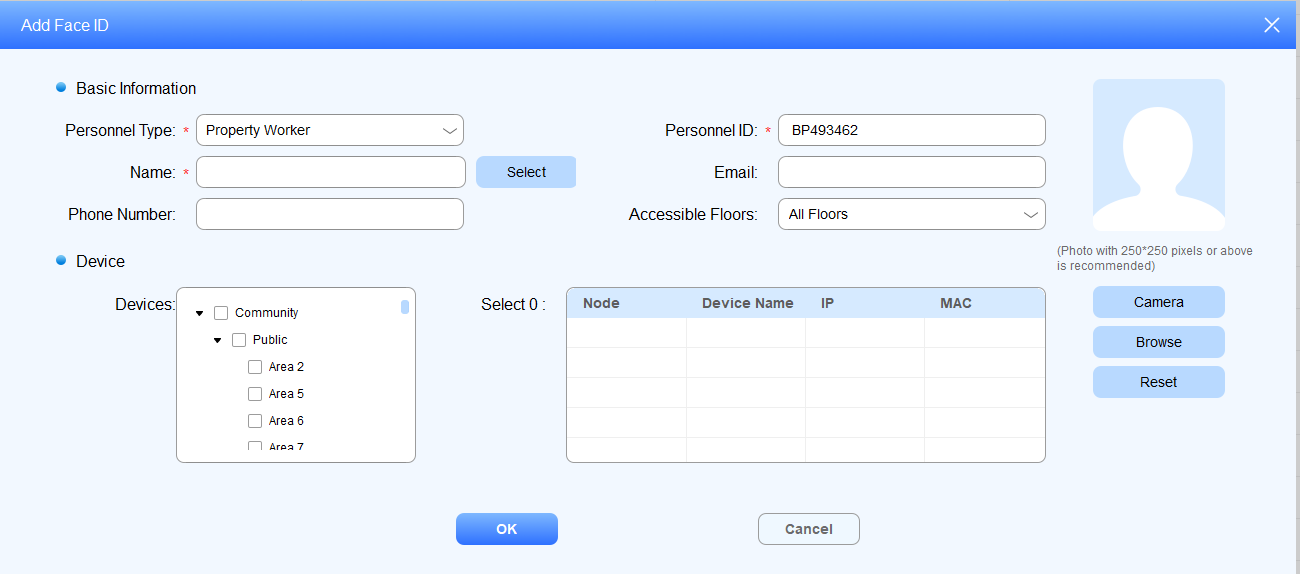
Navigate to Personnel Management > Verification Mode > Face ID (on the left column) >
 .
.Select Personnel Type.
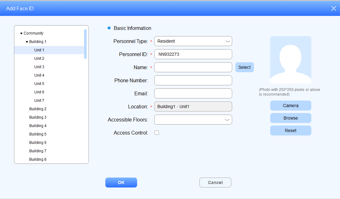
Select Resident type
Enter the resident’s name, or you can click
 to select the resident from the existing residents’ name list, and fill in other information.
Select the room node for the resident in the left column. (The resident will be able to access the building in which the room is located.)
Upload the resident’s picture to SDMC.
Select Property Worker type
Enter the property staff’s name, or you can click
 to select the staff from the existing property staff name list, and fill in other information.
Select the specific nodes (locations) where you allow the property staff to access.
Upload the property staff’s picture to SDMC
Import/Export Face IDs
You can import face IDs to SDMC for residents and property staffs for a quicker and larger scale face ID enrollment, and export the data for backup.
Navigate to Personnel Management > Verification Mode > Face ID (on the left column) >
 .
.
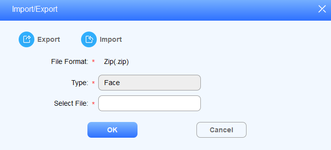
2. Click , and select the .zip file, then import the file to the SDMC.
3. Click to export the .zip face data out of the SDMC to your local PC.
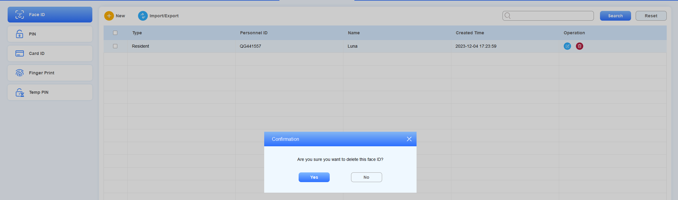
Check/Edit/Delete Face Data
Navigate to Personnel Management > Verification Mode > Face ID
Search the face ID by personnel ID, Name in the fuzzy search field. Reset the search keyword if needed.
Tick the checkbox of the desired face ID to delete or tick
 to delete all.
Click
 to edit the information.
Click
 of the specific resident and property staff for the deletion.
Private PIN Code
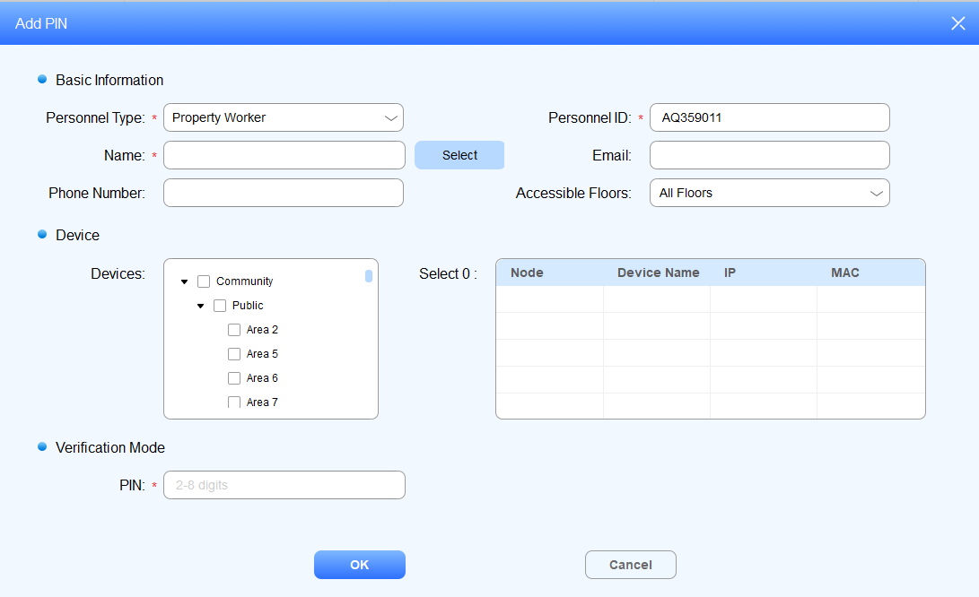
Create Private PIN Code
Private PIN code is used by the residents for door opening.
Navigate to Personnel Management > Verification Mode > PIN >
 .
.Select Personnel Type:
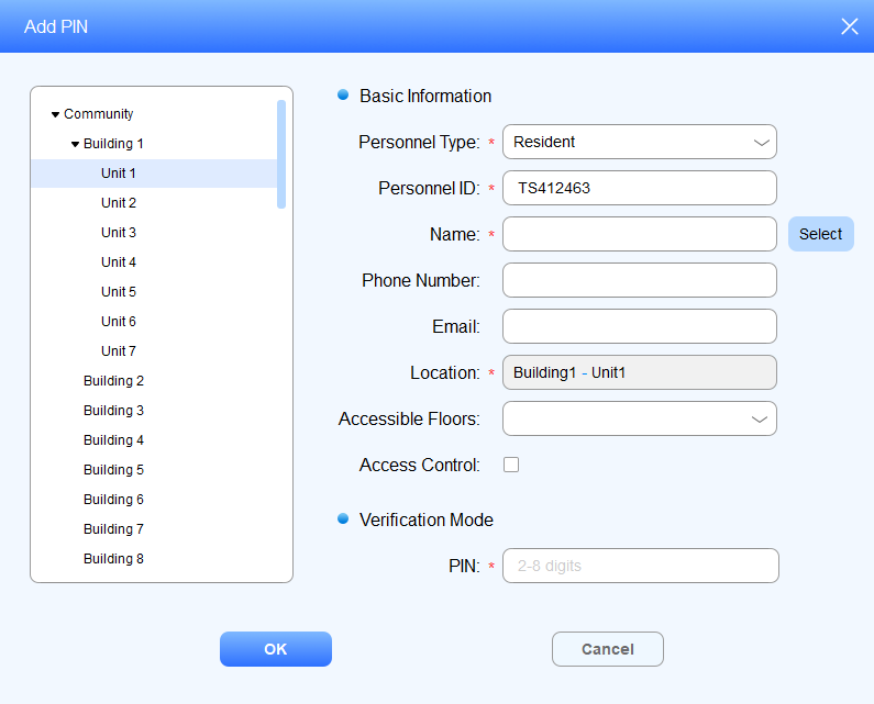
Select Resident type
Enter the resident’s name, or you can click
 to select the resident from the existing residents’ name list, then fill in other information.
Select the room node for the resident in the left column. (The resident will be able to access the building in which the room is located.)
Create a private PIN code for the resident.
Select Property Worker type
Enter the property staff’s name, or you can click
 to select the staff from the existing property staff name list, then fill in other information.
Select the specific nodes (locations) where you allow the property staff to gain access to.
Create a private PIN code for the resident.
Import/Export Private PIN Codes
You can import private PIN codes to SDMC for residents for a quicker and larger number of PIN code setup, and export the data for backup.
Navigate to Personnel Management > Verification Mode > PIN >
 .
.
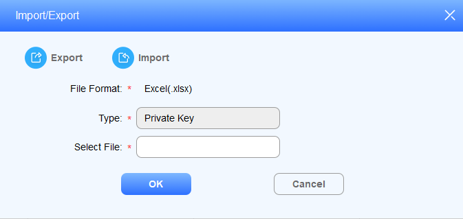
2.Click , and select the .zip file, then import the file to the SDMC
3.Click to export the .zip private PIN code data out of the SDMC to your local PC.
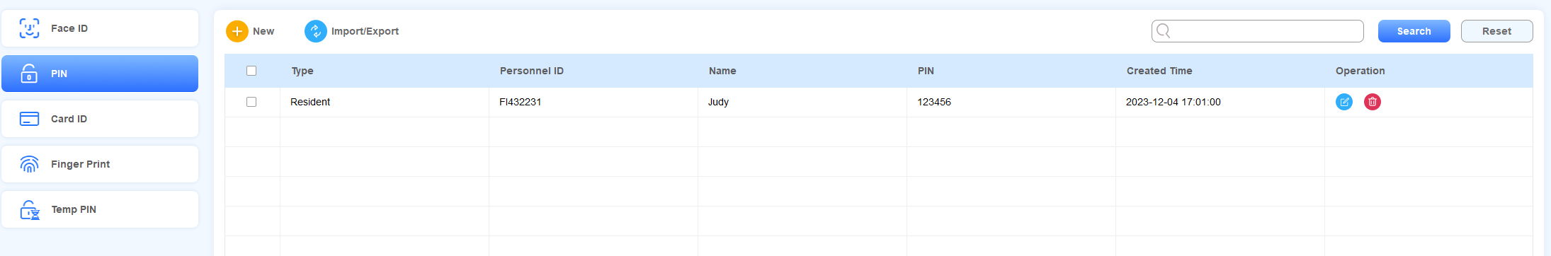
Search/Edit/Delete Private PIN Codes
Navigate to Personnel Management > Verification Mode > PIN.
Search the Private PIN code by Personnel ID, Name in the fuzzy search field. Reset the search keyword if needed.
Tick the checkbox of the desired PIN code for deletion, or you can tick
 to delete all.
Click
to edit the information.Click
.png) of the specific resident and property staff for the PIN code deletion.
of the specific resident and property staff for the PIN code deletion.
Card ID
Create Card ID
You can create an access card number for both residents and the property manager.
Navigate to Personnel Management > Verification Mode > Card ID >
 .
.Select Personnel Type:
Select Resident type
Enter the resident’s name, or you can click
 to select the resident from the existing residents’ name list, then fill in other information.
Select the room node for the resident. (The resident will be able to access the building in which the room is located.)
Click
 to obtain the card number for the card reader, or you fill in the card number manually.
Select Property Worker type
Enter the staff’s nam,e or you can click
 to select the resident from the existing property staff’s name list, then fill in other information.
Select the specific nodes (locations) where you allow the property staff to gain access to.
Click
 to obtain the card number for the card reader, or you fill in the card number manually.
Import/Export Card IDs
You can import access card number for residents and property staffs in batch, and export the data for backup.
1. Navigate to Personnel Management > Verification Mode > Card ID >  .
.
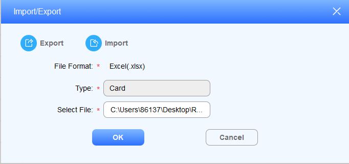
2. Click  , and select the .xlsx file, then import the file to the SDMC.
3. Click to export the .xlsx card data out of the SDMC to your local PC.
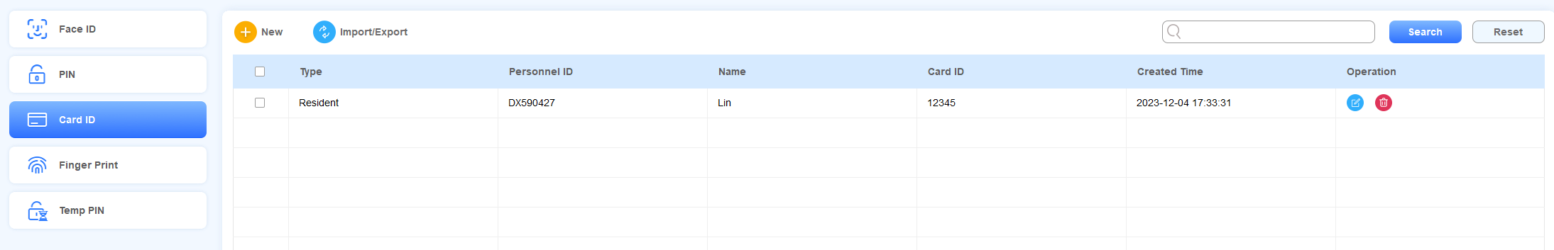
Search/Edit/Delete Card ID
Navigate to Personnel Management > Verification Mode > Card ID.
Search the face ID by Personnel ID, Name in the fuzzy search field. Reset the search keyword if needed.
Tick the checkbox of the desired card ID for the deletion, or you can tick
 to delete all.
Click to edit the information.
Click
.png) of the specific resident or property staff for the card ID deletion.
of the specific resident or property staff for the card ID deletion.
Finger Print
Enroll Finger Print
Navigate to Personnel Management > Verification Mode > Finger Print >
 .
.Select Personnel Type:
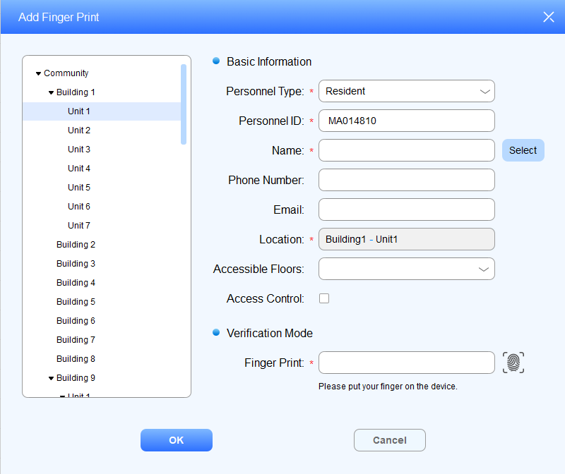
Select Resident type
Enter the resident’s name, or you can click
 to select the resident from the existing residents’ name list, then fill in other information.
Select the room node for the resident in the left column. (The resident will be able to access the building in which the room is located.)
Click
 to obtain the finger print code from the finger print reader, or you can fill in the code number.
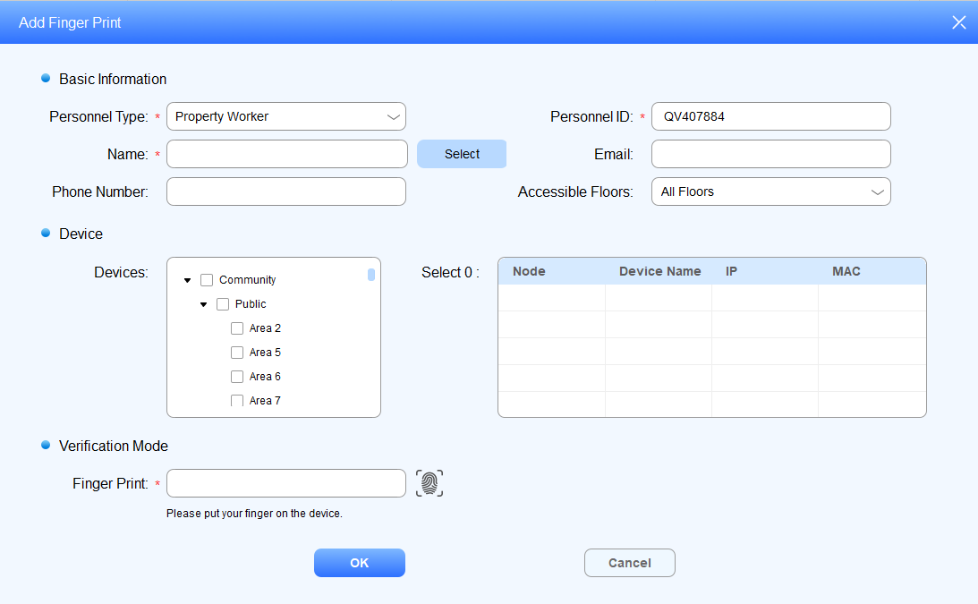
Select Property Worker type
Enter the property staff’s name, or you can click
to select the staff from the existing property staff name list, then fill in the other information.Select the specific nodes (locations) where you allow the property staff to access.
Click
to obtain the finger print code from the finger print reader, or you can fill in the code number.
Import/Export Finger Print Data
You can import finger print data to SDMC for residents and property staffs for a quicker and larger scale enrollment, and export the data for backup.
Navigate to Personnel Management > Verification Mode > Finger Print >
 .
.
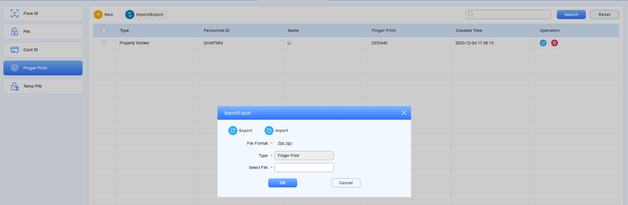
3.Click , and select the .zip file, then import the file to the SDMC.
4.Click to export the .zip fingerprint data out of the SDMC to your local PC.
Check/Edit/Delete Finger Print Data
Navigate to Personnel Management > Verification Mode > Finger Print.
Search the fingerprint data in the fuzzy search field by Personnel ID, Name, and Finger Print code.
Click
to edit the information.Click
 of the specific finger print for deletion or tick
  to delete all.
Note
Do not change the finer print code. Changes may result in invalid fingerprint authentication.
Temporary PIN Code
Create Temporary PIN Code
You can generate a temporary PIN code with validity time range for the visitors to access the location you selected.
Navigate to Personnel Management > Verification Mode > Temp PIN >
 .
.Enter the visitor’s name, and select the location that the visitor can access.
Enter the visitor’s email for receiving the temporary PIN.
Select the floor number that the visitor can access.
Click
 to generate a temporary PIN code for the visitor, or enter the PIN code manually.
Set the PIN code validity time range, and press OK to save the configuration.
Field Name Description
Field Name | Description |
Visitor Name | Enter the visitor's name, which should be 63 digits maximum in length. The visitor’s name can be seen in the access log. |
Visitor Location | Select the location (node) that you allow the visitor to access. The node you selected can be applicable upwards. For example, if you select the node “Building1,” then the visitor is also allowed to access the “Community1” node, which is above the Building node. |
Email should be no more than 255 characters. | |
Accessible Floors | You can select up to 10 floor numbers. When All Floors is selected, other options cannot be selected. |
Temp PIN | Temporary PIN code should be 2-8 digit numbers starting with the number 9. You can change the PIN code after it's been generated. |
Valid Period | Set the validity time range for the temporary PIN code. The default valid time range is “00:00:00-23:59:59” of the day. |
Check/ Edit /Delete Temporary PIN Code
After the Temporary PIN code is generated, you can change the visitor’s information in terms of their names, visiting location, emails, and temporary PIN code, along with its validity time range if needed.
Navigate to Personnel Management > Verification Mode > Temp Key.
Search the temporary PIN code in the search field by personnel ID, name, and temporary PIN code.
Click
to edit the information.Click
 of the specific temporary PIN code for deletion or tick
  to delete all.
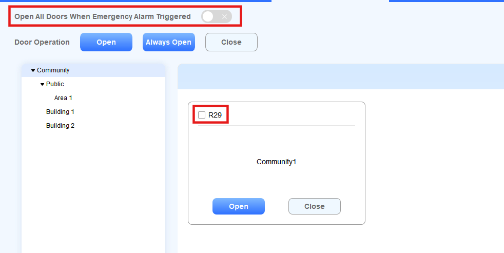
Emergency Unlock
You can make doors open automatically or manually during emergencies. For example, during a fire emergency, the doors can be opened automatically once an emergency alarm is triggered on any one of the door phones so that people can be quickly evacuated to a safer place. Also, you can open doors manually on the SDMC in an emergency.
Go to Device Management.
Click Emergency Unlock.
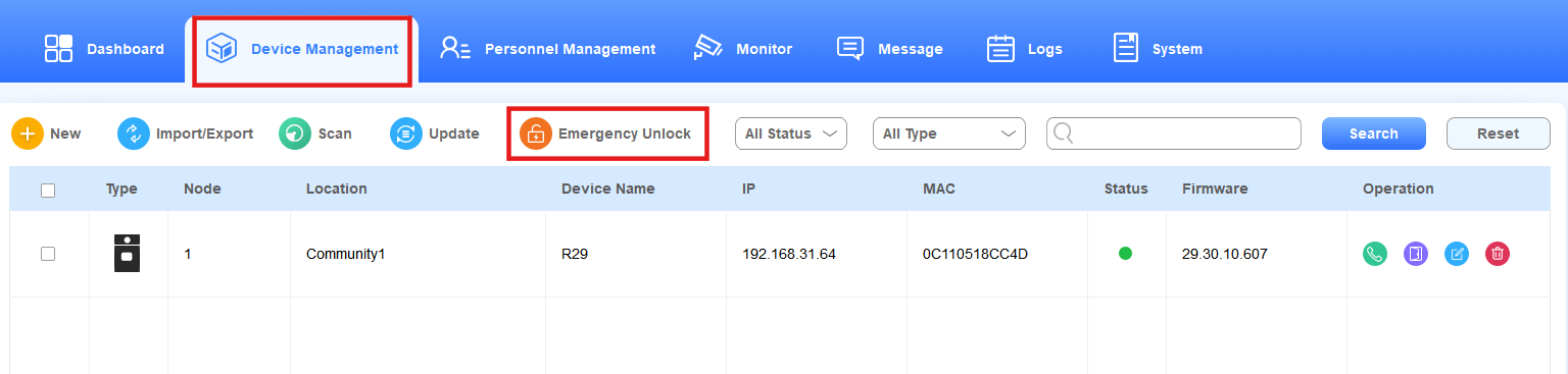
Select automatic door unlock or manual unlock.
Enable Open All Doors when Emergency Alarm Triggered to open doors automatically when an emergency occurs.
If disabled, you can check the device(s) and click Open to open the doors manually. Click Hold Open to keep it open until you click Close to close it manually.
Note
To use this feature, the emergency action should be set up on the device.
Click here to view the details.
Monitor
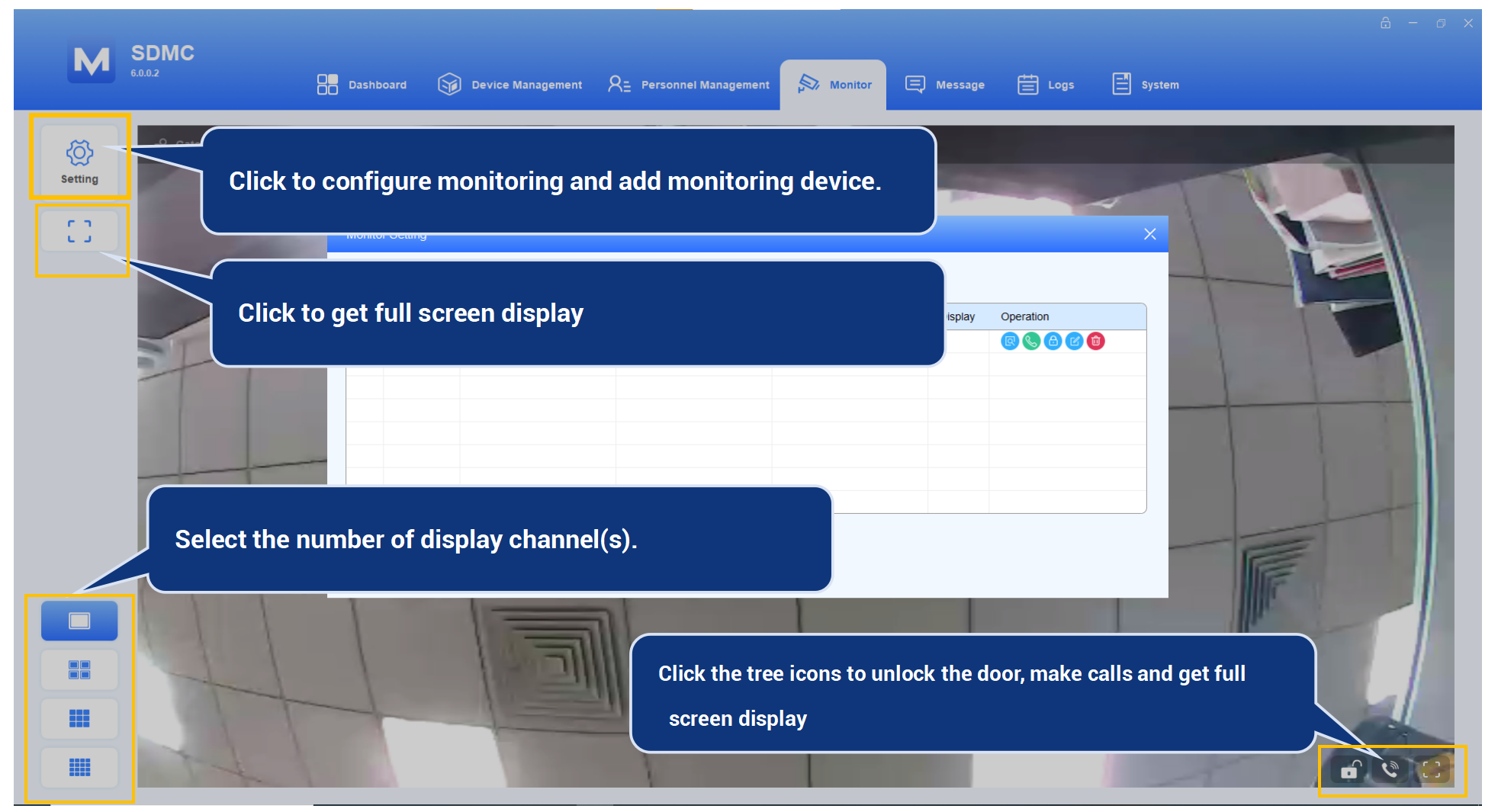
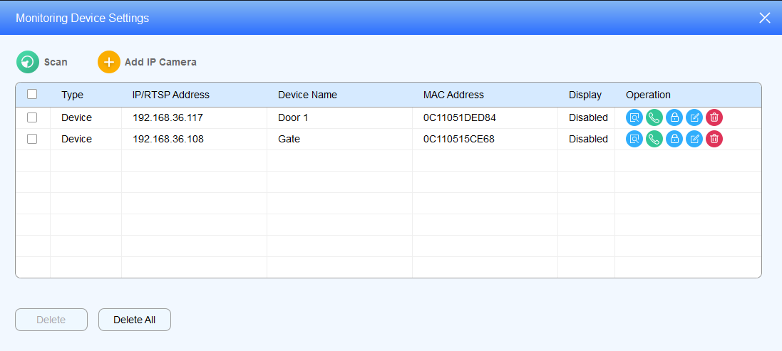
Add Monitoring Devices
You can add Akuvox door phones as monitoring devices in the same LAN network via scanning, and you can also add a third-party IP camera for monitoring.
Add Akuvox Door Phone via Scanning
Click
 and click
  .
.Tick the checkbox of the desired door phone and click
 .
.
Enter the RTSP username and password for authentication, and select the number of the channel display.
Enter the relay username and password for authentication, and enable relay(s) as needed.
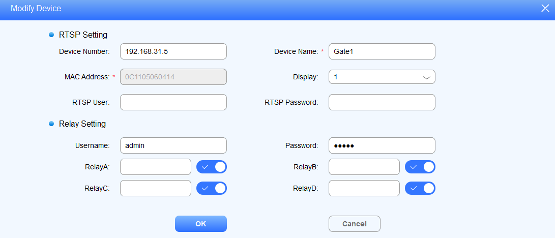
Field Name Description:
Field Name | Descriptions |
Device Number | Shows the monitoring device IP address. |
Device Name | Shows the monitoring device name by location. |
MAC Address | Shows the monitoring device's MAC address. |
Display | Select the number of channels if you want to view the monitoring video (from 1 to 16 channels). |
RTSP User | Enter the door phone RTSP username for authentication. |
RTSP Password | Enter the door phone RTSP password for authentication. |
Username | Enter the door phone relay username for authentication. |
Password | Enter the door phone password for authentication. |
Relay A/B/C/D | Enable the relay(s) that can be triggered while you are monitoring. |
Note
The number of channel selected should be matched with channel display icon you selected. For example, if you select “5” for the channel display, and you select
, then the video will not displayed. You should select the channel icon greater than 5.
Add a third-party IP camera
Click
 and then
  .
.Fill in the RTSP URL of the IP camera.
Fill in the IP address of the access-controlling door phone.
Enter the device name of the IP camera, and select the number of display channels.
Enter the relay username and password for the authentication.
Enable the relay(s) as needed.
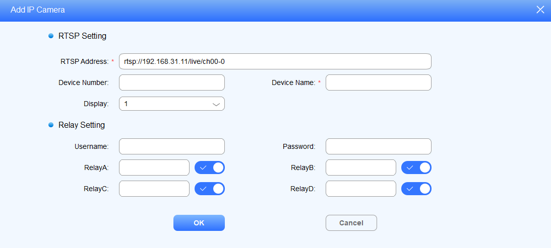
Field Name Description:
Field Name | Descriptions |
RTSP Address | Enter the RTSP address in the URL format provided by a third-party IP camera. |
Device Number | Enter the IP address of the device. |
Device Name | Enter the IP camera name, for example, by its location. |
Display | Select the number of channels if you want to view the monitoring video (from 1 to 16 channels). |
Edit/Delete Monitoring Device
You can edit and delete the monitoring device if needed.
Click
 to delete the desired device, or tick
  to delete all.
Click
 to edit settings.
Preview/Call/Unlock
After the monitoring device is set up, you can preview the video image from the monitoring device to see who is standing at the door station, while making a call to the person before you open the door.
Click
 of the monitoring device to take a preview of the video image.
Click
 to call the monitoring device.
3. Click  to unlock the access-controlling door phone.
In addition, you can re-select the monitoring device after taking a quick view of the full-screen video footage.
Click on the upper area highlighted in the red box.
Select the desired monitoring device.
Message
Create/Draft/Send Message
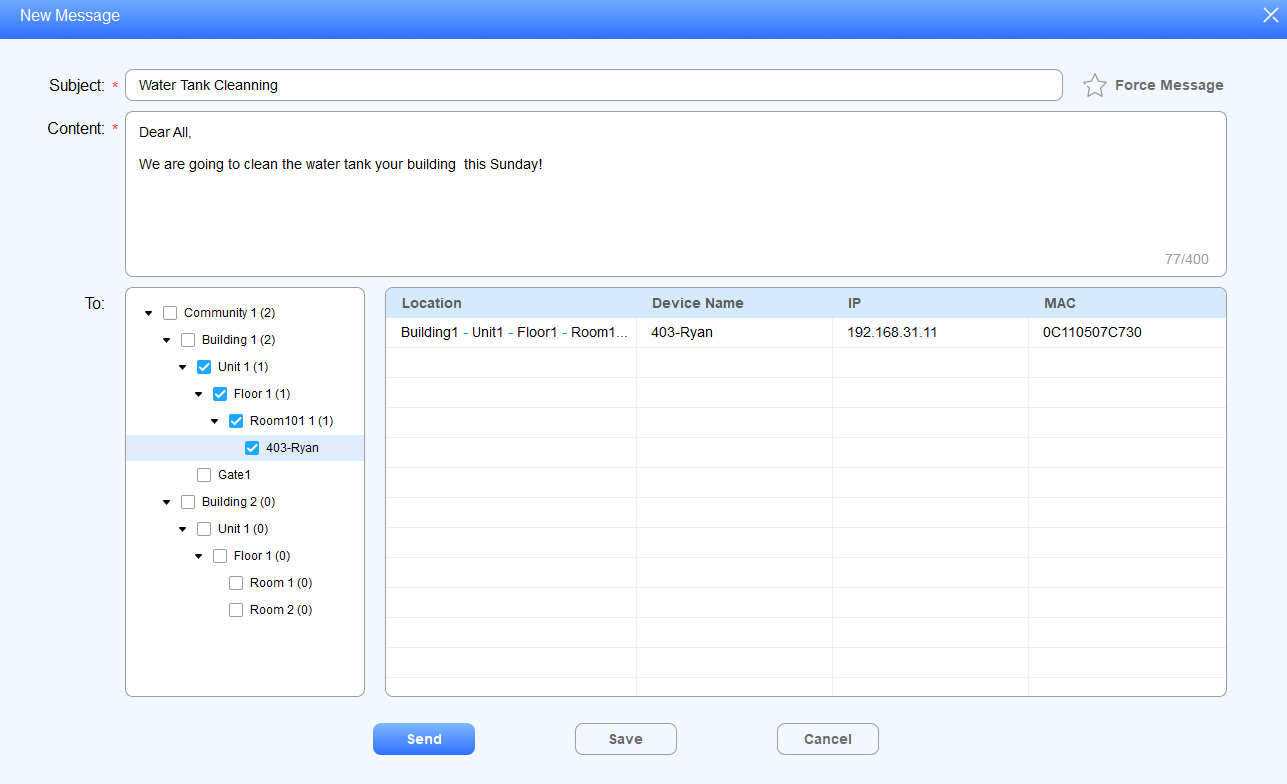
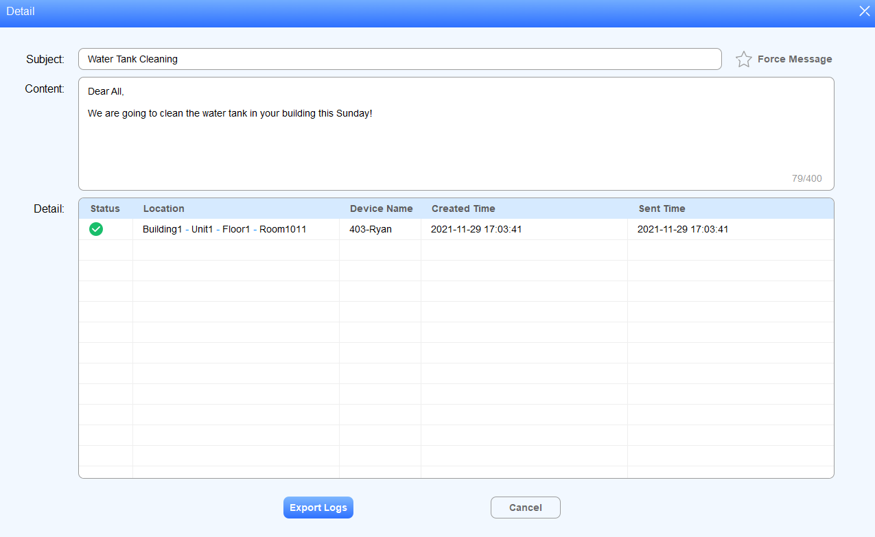
You can create, draft, and send messages or notifications to the targeted residents or to all residents in the community.
Click Message > Text Message >
.png) .
.Create the subject and the message, then select the specific residents (by their room node(s))
Click Send to send a message to the device (e.g., indoor monitor) you selected, or you can click Save to save the message as a draft for later use if needed.
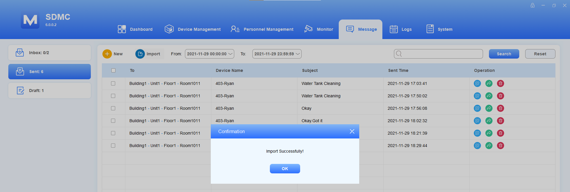
Import/Export Message
You can import the message template file from your local PC to SDMC, and the message in the file will be automatically sent to the designated device node. You can also export the received messages.
Import/Send Message to Residents
Navigate to Message > Text Message > Sent.
Click
 to select the .xlsx message file from your local PC, and import the message file to the SDMC, which will send the message to the specific device node.
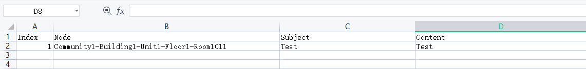
Import Template:
Export Message
Click
 of the specific message you want to export.
2. Click to export the message to your local PC.
Check/Reply/Forward/Delete/Edit Message
Check/Reply/Forward/Delete Received Messages
You check, reply, forward, and delete the messages in the inbox.
Select Message > Text Message > Inbox.
Search the message by Date/All/Unread/Read, or enter the keyword in the fuzzy search field by Device Name or Subject.
Click
 to check the message details. You can also forward or reply to the message.
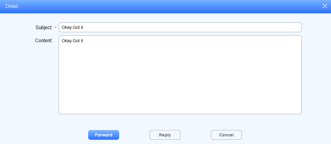
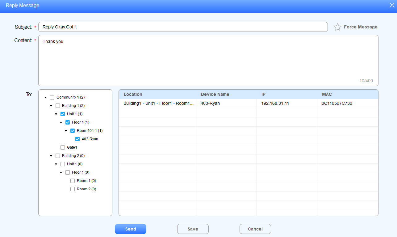
Click
 to reply to the message in the same way as you create a new message.
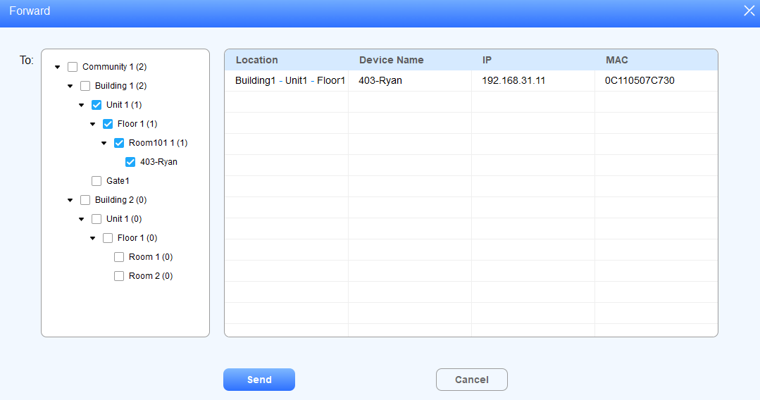
Click
 to forward the message to other residents and select the node(s) to which you want to forward the message.
Click
 to delete the message.
Note
The two numbers on both side of “/” indicate the total number of received message and unread messages. For example
, 2 is total number of messages, 0 is the total number unread message.
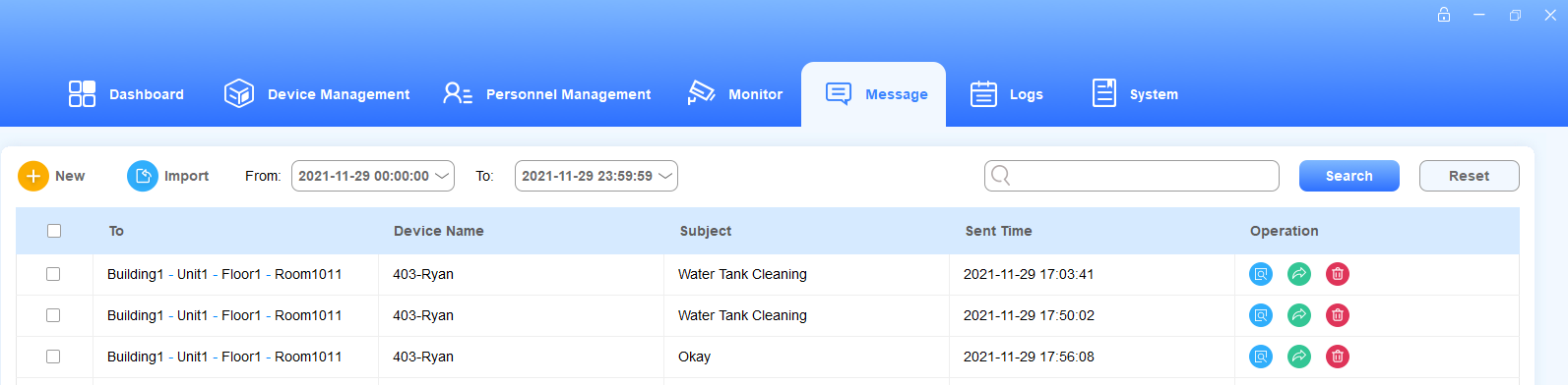
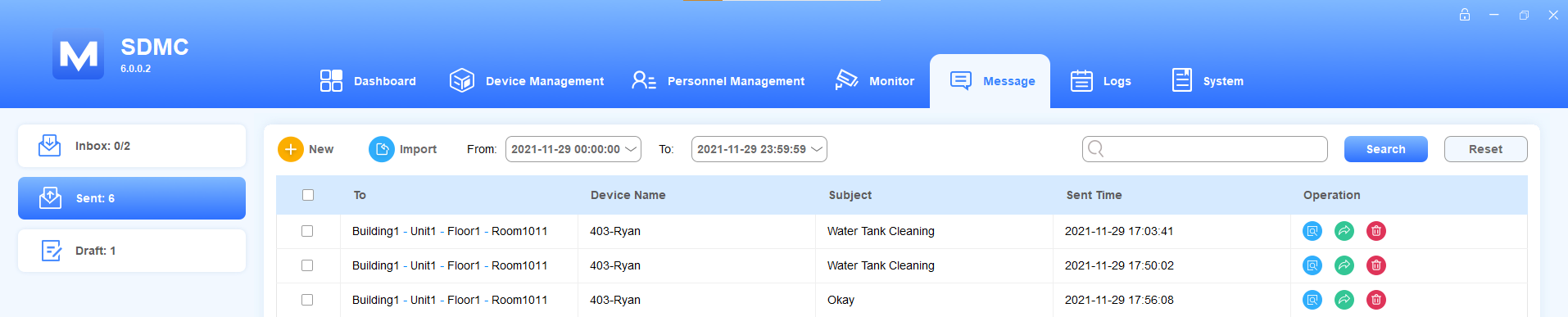
Check/Forward/Delete Sent Messages
Select Message > Text Message > Sent.
Search the message by Date, or enter the keyword in the fuzzy search field by Device Name or Subject.
Click
 to delete the message, or tick
  to delete all.
Click
 to check the message.
Click
 to forward the message to other residents and select the node(s) to which you want to send the message.
Edit/Delete Draft Messages
You can edit and delete the draft message before sending it to targeted residents.
Select Message > Text Message > Draft.
Search the message by Date, or enter the keyword in the fuzzy search field by Device name, Subject.
Click
 to delete the message, or tick
 to delete all.
Click
 to edit the message and select the node(s) to which you plan to send the message.
Gas Data
SDMC can receive gas data sent by the indoor monitor and allows you to export the data by month.
1. Click Message > Gas Data.
2. Search the gas log by date.
3. You can click.png) to edit the gas value with a maximum of 10 digits. Only numbers and decimal points can be entered.
to edit the gas value with a maximum of 10 digits. Only numbers and decimal points can be entered.
4. You can click  to delete the log.
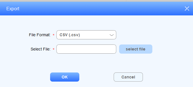
5. You can click  to export the log in either .csv or .xlsx format to your PC.
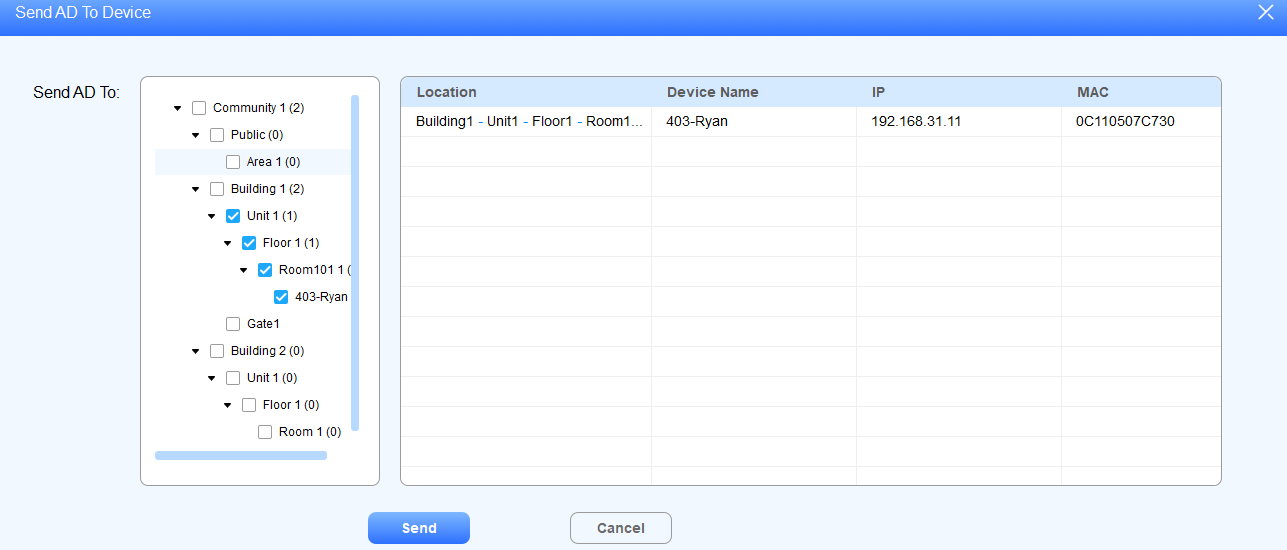
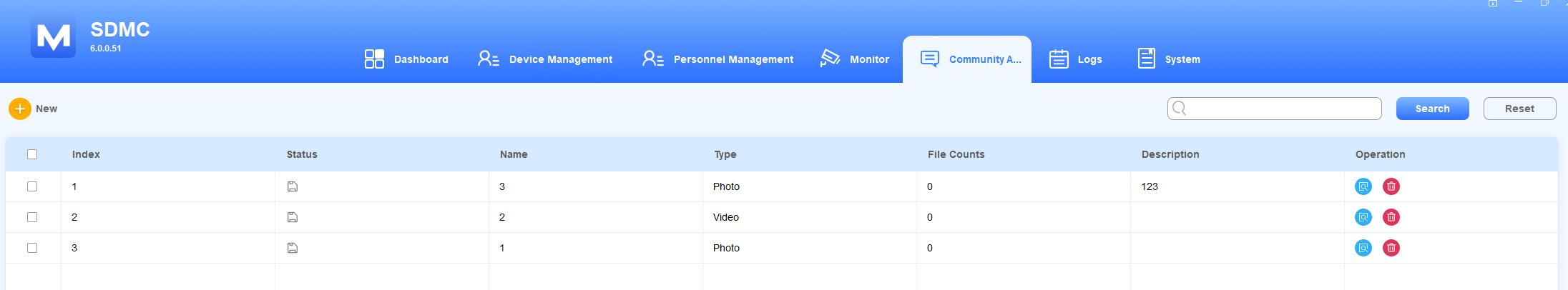
Ad Pushing
Photo/Video Ads
You can upload the Ad pictures and videos to the SDMC and synchronize them to the targeted residents’ indoor monitors. And the pictures and videos will be displayed in rotation according to the display duration you set.
Click Message > Community Advertisement >
 .
.Select the File Type.
Photo Ad
Name the picture.
Enter the description for the ad.
Click Import to upload the picture to SDMC, and set the display duration.
Click Save to save the picture, and click Send To Device if you want to synchronize the picture to the device.
Select the device to which you want to synchronize the picture(s) by nodes, then click Send for confirmation.
Field Name Description:
Field Name | Descriptions |
File Type | Select a photo or video ad according to you need. |
Name | Create an Ad list name for the convenience of management and categorization |
Description | Enter the description for ads, for example, you can enter the owner of the ads and the ad expiration date, etc. |
Files: Name | Shows the file name of the picture |
Duration | Set the rotational display duration of the pictures. The duration can be 10s, 20s, 30,60s, 120s,180s,240s, 300s, 600s, 1200s, 1800s,3600s, and 10s (default duration). For example, if you select “10s” for the duration, then a picture will be displayed for 10 seconds before it changes to the next one. |
Preview | Display the preview of the picture. |
Note
The picture should be .jpg, jpeg, and png format with recommended dimension of 1920*1080.
Video Ad
Name the video.
Enter the description for the video.
Click Import to upload the video to SDMC, and set the display duration.
Click Save to save the configuration, and click Send To Device if you want to synchronize the video to the device.
Select the device to which you want to synchronize the video(s) by nodes, then click Send for confirmation.
Note
The video should be mp4, wmv, and avi format.
Check/Delete/Edit Ads
Click Message > Community Advertisement.
Search the ads by Name and Description in the fuzzy search field.
Click
to edit the ad.Click
to delete the ad. The ad synchronized to the indoor monitor will also be deleted.
Logs
Logs module allows you to manage six types of logs: Access Logs, Alarm Logs, Call Logs, Video Records, Motion Detection, and System Logs.
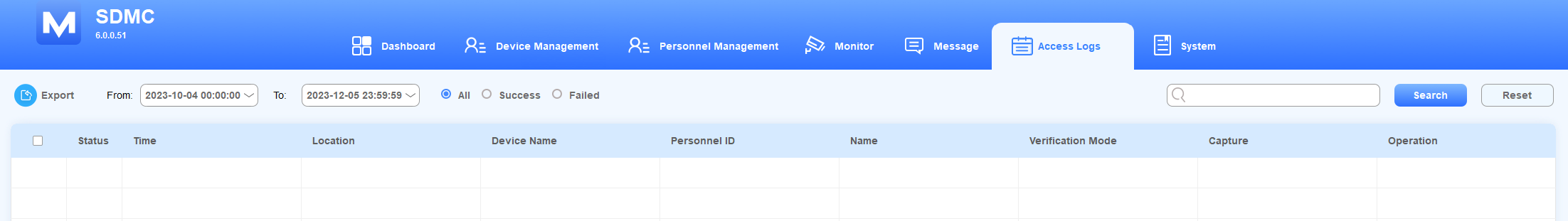
Access Logs
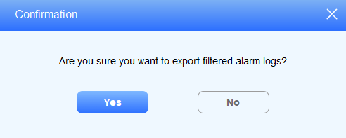
Search/Check/Delete/Export Access Logs
Click Logs > Access Logs.
Search the access logs by Name, Location, Personnel ID, or Device Name in the search field.
Click
 to see the picture captured.
Click
 to delete the log.
Click
to export the log to your PC.
Alarm Logs
Search/Check/Delete/Export Alarm Logs
Click Logs > Alarm Logs.
Search the alarm log by All/Dealt/Undealt or Location in the search field.
Click
 of the alarm logs if you want to enter remarks for the alarm you have dealt with.
Click
 to delete the log.
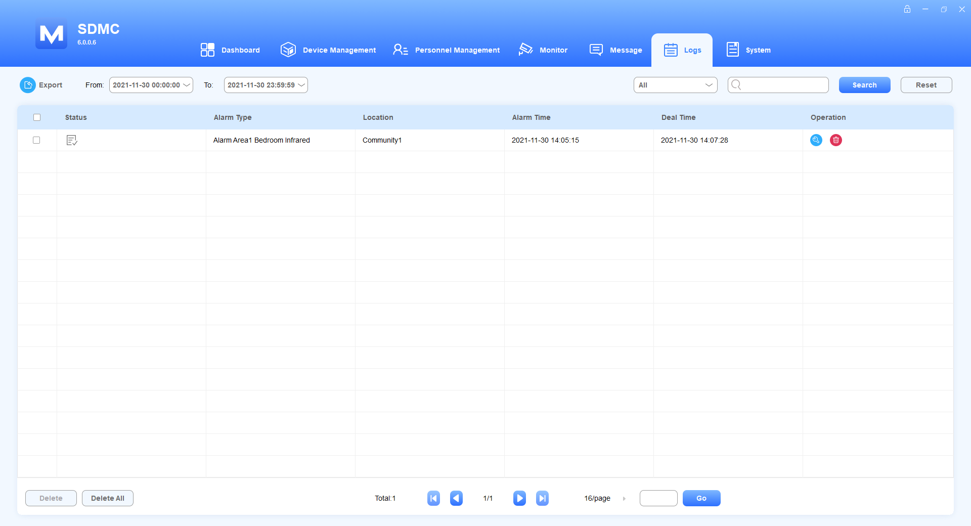
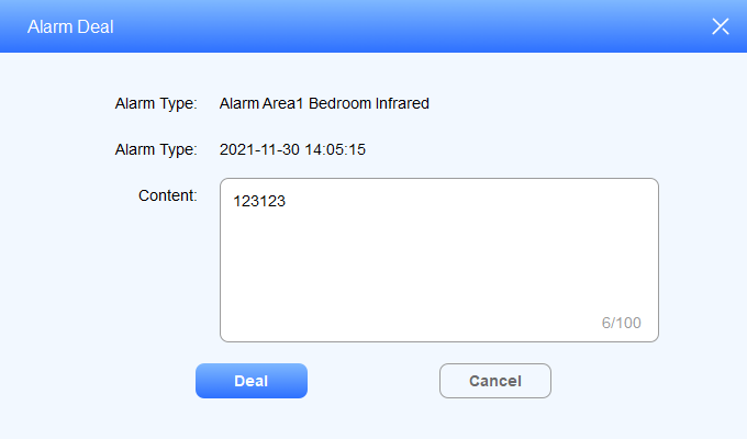
5. Click to export the log to your PC.
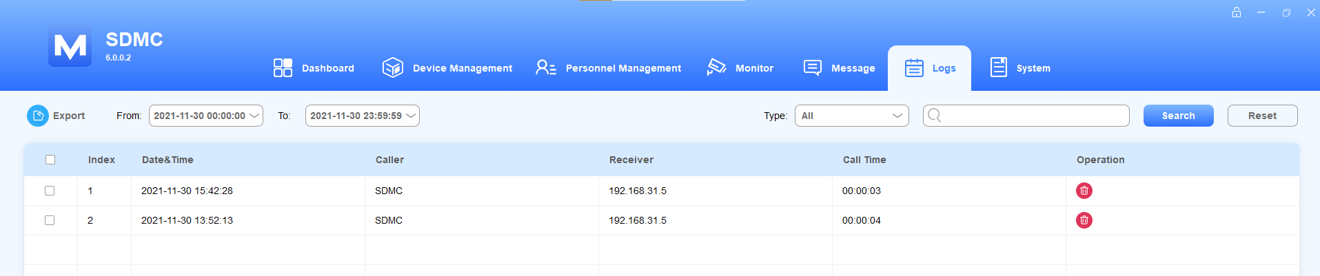
Call Logs
Search/Check/Delete/Export Call Logs
Click Logs > Call Logs.
Search the call log by date, type, or location in the search field.
Click
 to delete the log.
Click
 to export the log to your PC.
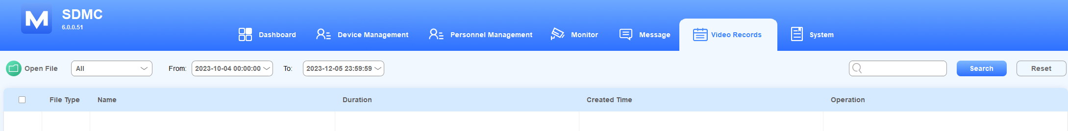
Video Records
Search/Check/Delete/Export Video Records
Click Logs > Video Records.
Search the call log by date or name in the search field.
In Operation field, you can click the picture to see the enlarged one,
 to play the audio or video record, and to delete the log.
Click Open File to see the downloaded files.
Note
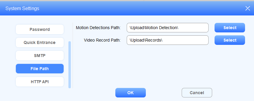
You can change the file path for storing video records. Go to System > System Settings > File Path and click Select to choose the file path.
Motion Detection
Search/Check/Delete/Export Motion Detection Records
Click Logs > Motion Detection.
Search the motion detection log by date, name, or location in the search field.
In Operation field, you can click the picture to see the enlarged one and
to delete the log.Click Open File to see the downloaded files.
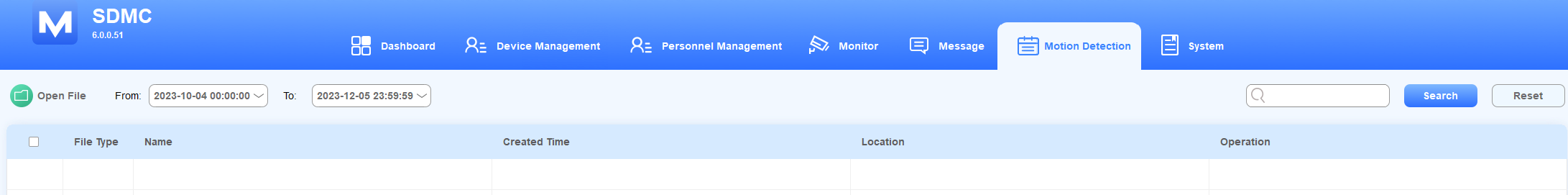
Note
You can change the file path for storing motion detection records. Go to System > System Settings > File Path and click Select to choose the file path.
System Logs
The system module allows you to monitor all the system operations that have occurred in the SDMC. You can check system logs and export the log to your PC.
Search/Export Logs
Click Logs > System Logs.
Search the logs by date or keyword in the search field.
Click
 to export the system logs to your PC.
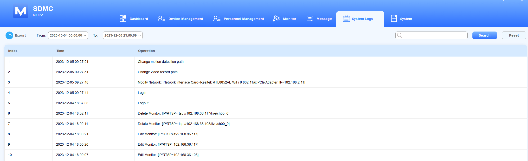
Operation code examples
System log is composed of the operation code starting with a verb.
Operation Verb | Descriptions |
Login | Indicates a Login operation, meaning someone has logged into the SDMC. |
Send | Indicates a Send operation, for example,” Send AD List: [ Device Name=403-Ryan; Adlist Name=Test-2” means the AD list has been sent to the device (403-Ryan) with Ad list name “Test-2”. |
Modify | Indicates an Modfiy operation, Modify Network [Network Interface Card=192.168.31.15, IP=192.168.31.19, meaning the network adaptor IP address has been changed to 192.168.31.19. |
System
SIP Settings
You are required to configure SIP settings for the SDMC before you can make SIP calls from the SDMC to the devices.
Click System > SIP Settings.
Configure the SDMC SIP settings.
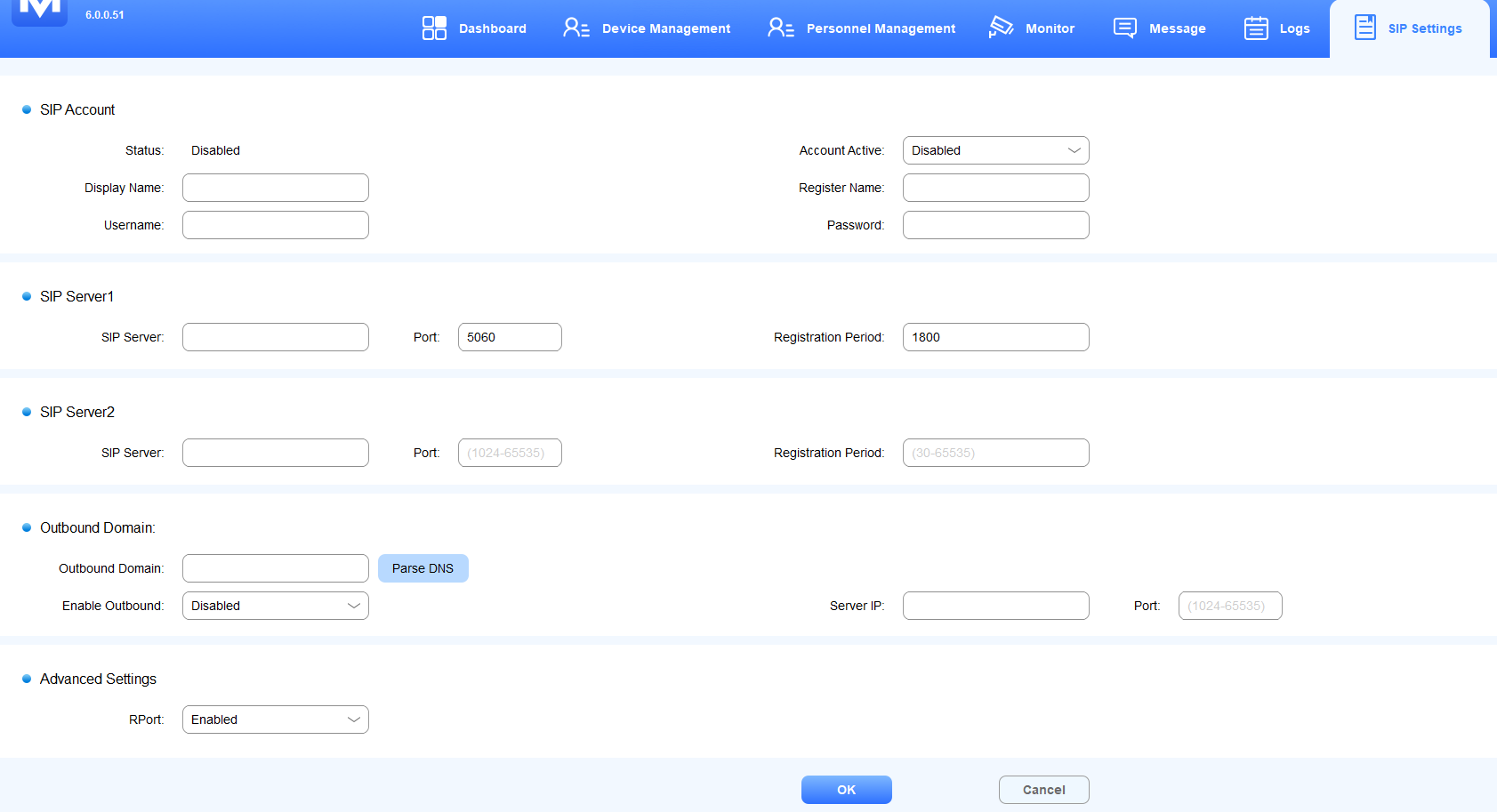
Field Name Description
Field Name | Sub-field Name | Descriptions |
SIP Account | Status | Displays whether the SIP account is registered or not. It will show Enabled when the account is registered. |
Account Active | Enable or disable the registered SIP account. | |
Display Name | It can be the device's name shown on the called-party device. You can fill in 63 bytes of characters in length. | |
Register Name | The SIP account register name is obtained from the SIP account administrator. You can fill in 63 bytes of characters in length. | |
Username | The SIP account username is obtained from the SIP account administrator for authentication. You can fill in 63 bytes of characters in length. | |
Password | The password obtained from the SIP account administrator for authentication. | |
SIP Server1/2 | SIP Server | SIP server IP address or its URL. |
Port | SIP server port for data transmission. | |
Registration Period | SIP account registration time pan. SIP re-registration will start automatically if the account registration fails during the registration time span. The registration period ranges from 30-65535s with 1800 default. | |
Outbound Domain | Outbound Domain | The domain name (DNS) provided by the outbound proxy server provider. |
Enable Outbound | Enable or disable the outbound proxy server. | |
Server IP | The outbound SIP server IP address or its URL. | |
Port | The outbound SIP server port for data transmission. | |
Advanced Settings | RPort | Enable the RPort when the SIP server is in a WAN(Wide Area Network). |
Note
An outbound proxy server is used to receive all initiating request messages and route them to the designated SIP server for data transmission.
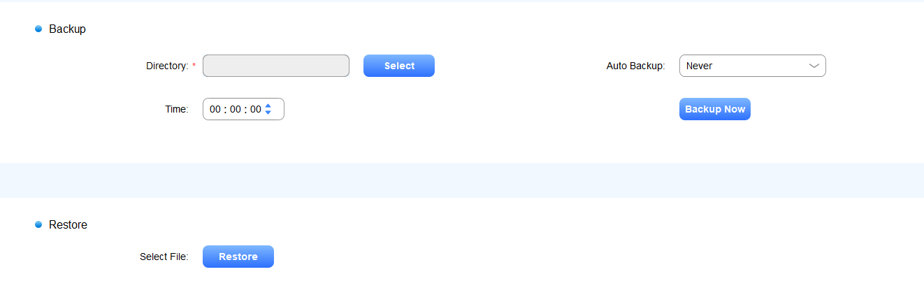
Backup & Restore
SDMC allows data to be stored in your computer automatically, which can be used to restore your SDMC database when data damage or breakdown occurs. You can set the auto-backup schedule for the database.
Click System > Backup & Restore.
Select Local Backup & Restore or Remote Backup & Restore.
Local Backup & Restore:
1. Select the file path and click Backup Now, or configure the auto-backup schedule.
2. Click Restore to upload data from your computer.
Remote Backup & Restore:
1. Configure FTP Server whose address, password, and username should be obtained from FTP server provider. You can click Test Connection to check whether the connection is set up and stable.
2. Click Backup Now or configure an auto-backup schedule.
3. Click Restore to upload data from your computer. 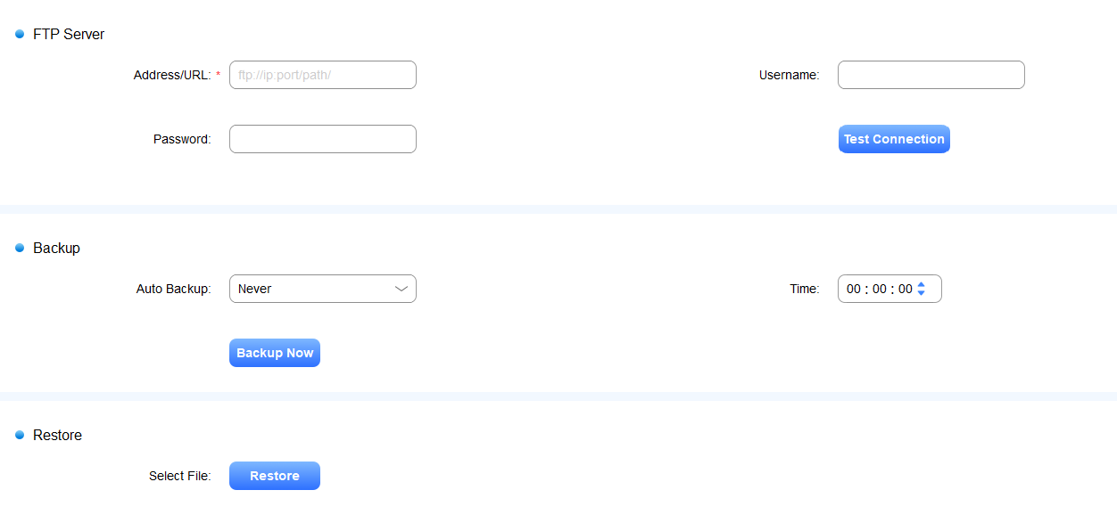
Device Backup & Restore
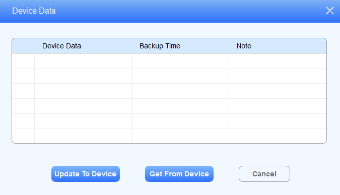
Update Autop Data to Device
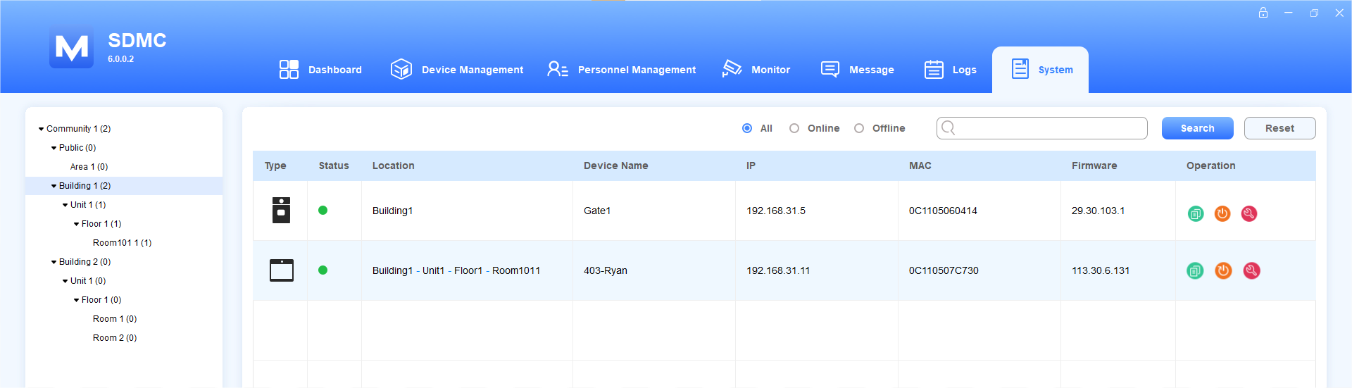
Click System > Device Backup & Restore.
Select the device by node on the left column or search for the device by Device Name, MAC, etc.
Click
 to update the Autop data of the desired device.
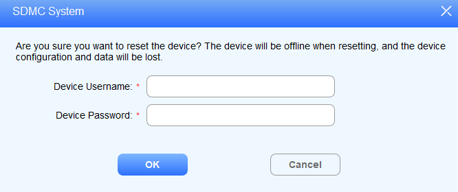
Reset the Device
You can reset the device remotely from your SDMC for device maintenance and troubleshooting.
Click System > Device Backup & Restore.
Select the device by node on the left column or search the device by Device Name, MAC, etc.
Click
.png) to reset the desired device.
to reset the desired device.Enter the authentication username and password.
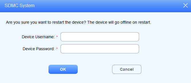
Reboot the Device
You can reboot the device remotely from your SDMC for device maintenance and troubleshooting.
Click System > Device Backup & Restore.
Select the device by node on the left column or search the device by Device Name, MAC etc.
Click
 to reboot the desired device.
Enter the authentication username and password.
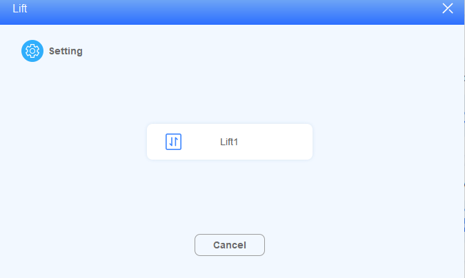
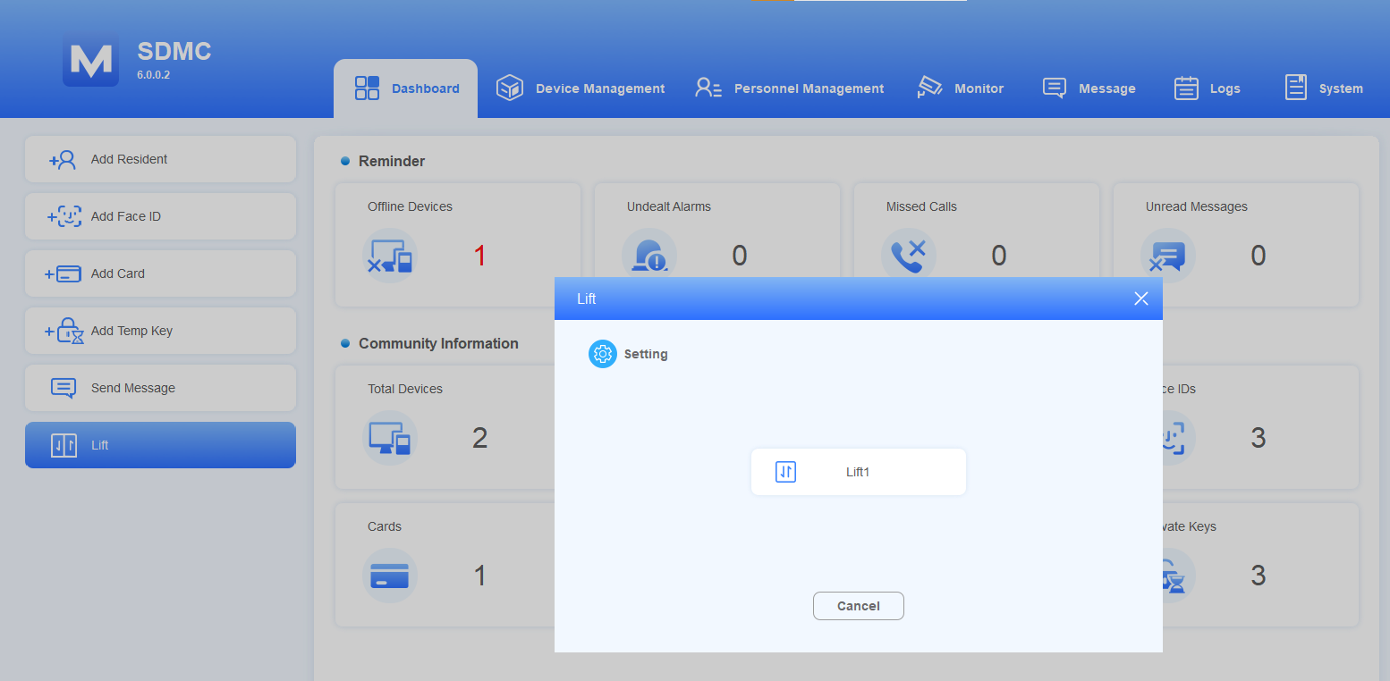
Lift Control
Click System > Lift Settings.
Click
 of the lift you want to control.
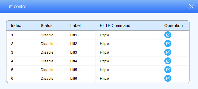
3. Enable the lift and edit the lift label.
4. Enter the HTTP command provided by the lift control manufacturer.
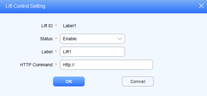
Click to summon the lift.
Field Name Description:
Field Name | Descriptions |
Label | Configure the lift label 1-6. The label should be 63 digits maximum in length. |
HTTP command | The HTTP command should be 255 digits maximum in length. |
Lift control can also be made on the dashboard by clicking System > Lift Settings.
System Setting
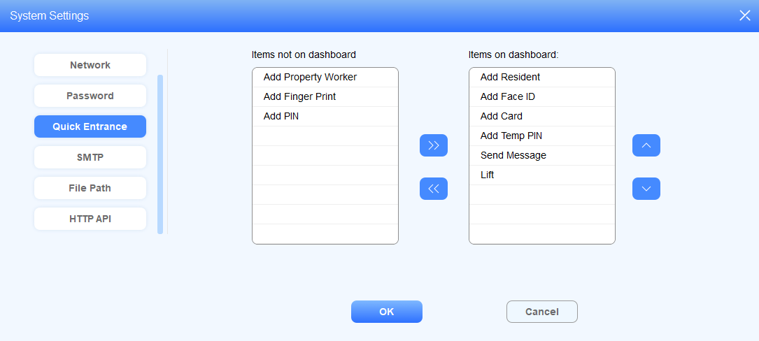
Quick Entrance
Quick Entrance allows you to configure operational icons on the dashboard for the quick and convenient of operations.
Click System > System Settings> Quick Entrance.
Move the operational icons left or right using

 and adjust the dashboard position of the operational icons by selecting
 .
.
SMTP
The SMTP server can be configured in your SDMC. When the alarm goes off or the door is opened, then a notification can be sent to the SMTP server.
Click System > System Settings > SMTP.
Configure the parameters.
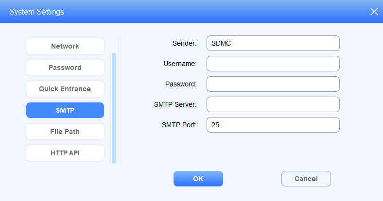
Field Name Description:
Field Name | Descriptions |
Sender | The sender name of the notification is SDMC by default. The sender name should be 63 characters maximum in length. |
Username | The SMTP server authentication username. |
Password | The SMTP server authentication password. |
SMTP Server | The SMTP server address. It should have a maximum of 255 digits in length. |
SMTP Port | The SMTP server port ranges from 1-65535, with 25 as the default. |
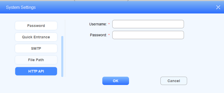
HTTP API
SDMC allows you to customize the username and password for authentication when obtaining the HTTP API.
1. Click System > System Settings > HTTP API.
2. Customize the username and password and click OK to save the configuration.
Contact Us
For more information about the product, please visit us at www.akuvox.com, or feel free to contact us by
Sales email: sales@akuvox.com
Technical support email: support@akuvox.com
Telephone: +86-592-2133061 ext.7694/8162
We highly appreciate your feedback about our products.