.jpg)
1. Overview
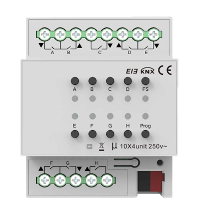
KXAC-B1C4
This 4-gang curtain Module provides manual control, scheduled execution, and real-time status monitoring, serving as a foundational element of home automation. Its precise control and user-friendly operation ensures a comfortable, efficient, and smart curtain management experience.
2. Wiring and Operation Elements
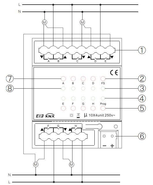
①Output/Load Terminals
②Manual/Automatic Mode Switch Button
③Manual/Automatic Mode LED
④Programming LED
- Green: Enter physical address programming mode
⑤Programming Button
⑥KNX Bus Terminals
⑦Relay Control Button
⑧Relay Status LED
3. Project Design and Application
3.1 Parameter Settings
General Setting
This page allows configuration of the device’s general settings.
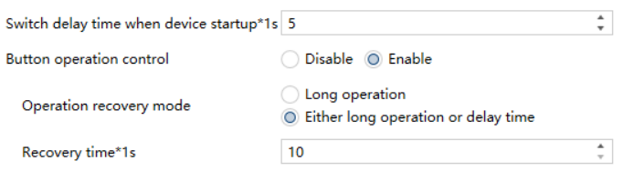
Parameter | Option | Description | Remark |
|---|---|---|---|
Switch delay time when device startup*1s | 1…60 | Defines the delay applied during device startup. | Applies only after a power-off restart. |
Button operation control | Disable Enable | Enables or disables manual operation via the physical button. | This parameter must be enabled to allow entry into manual operation mode via a long button press. |
Operation recovery mode | Long operation | Manual mode can be entered and exited exclusively by long-pressing the button. | |
Either long operation or delay time | Manual mode can be entered and exited either by long-pressing the button or automatically after the configured recovery time. | ||
Recovery time*1s | 10…3000 | Specifies the timeout for exiting manual operation if no button action occurs. | |
Channel Configuration
This page is used to select the applied product module and enable the corresponding channel functions. The available parameters are shown in the figure below.
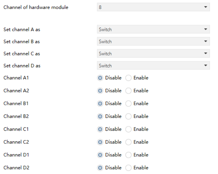
Parameter | Option | Description | Remark |
|---|---|---|---|
Channel of module | 4 8 16 28 | Selects the applied product module. | |
Set channel x as | Disable Switch Blind | Selects the function assigned to the specified channel. | |
Channel A1~N1 Channel A2~N2 | Disable Enable | Enables or disables the corresponding channel function. | Each channel is divided into two parts: 1 and 2. |
Switching x [x=A1~N2]
This page is used to configure the functional parameters of the switch channel.
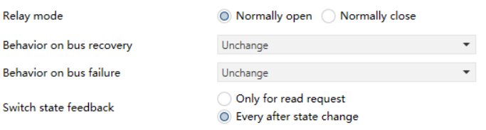
Parameter | Option | Description | Remark |
|---|---|---|---|
Relay mode | Normally open Normally close | Defines the control type of the connected load. | Normally open: load runs when powered, stops when unpowered. Normally close: load stops when powered, runs when unpowered |
Behavior on bus recovery | Unchange Open Close As before bus failure | Defines the relay contact action executed after the device restarts due to a bus power recovery. | This parameter applies only to device restart after a power failure. |
Behavior on bus failure | Unchange Open Close | Defines the relay contact action executed after the bus power fails. | |
Switch state feedback | Only for read request Every after state change | Defines the feedback mode for the switch state. |
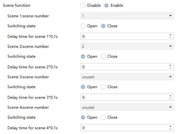
Parameter | Option | Description | Remark |
Scene function | Disable Enable | Enables or disables the scene function. | |
Scene x:scene number【x=1~8】 | Unused 1 2 … 64 | Assigns a scene number to the channel. | |
Switching state | Open Close | Defines the switch state when the scene is recalled. | |
Delay time for scene 1*0.1s | 0…255 | Sets the switch delay time for the scene channel. |
Channel x: Blind [x=A~N]
This page is used to configure the functional parameters of the blind (shutter) channel.
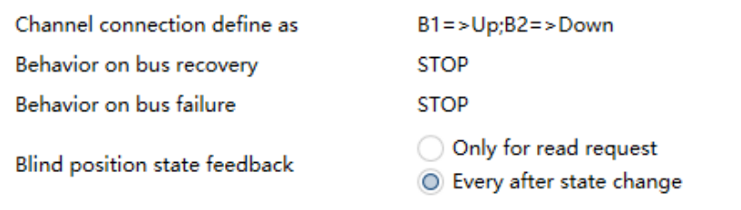
Parameter | Option | Description | Remark |
Switch state feedback | Only for read request Every after state change | Defines the switch state feedback mode |
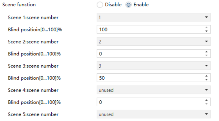
Parameter | Option | Description | Remark |
Scene function | Disable Enable | Enables or disables the scene function. | |
Scene x:scene number 【x=1~8】 | Unused 1 2 … 64 | Assigns a scene number to the scene channel. | |
Blind position | [0...100]% | Sets the blind position to be recalled when the scene is activated. |
3.2 Description of Communication Objects “Switch Actuator”
Communication objects serve as the interface through which the device exchanges information with other devices on the KNX bus. Only these objects are capable of sending and receiving KNX telegrams.
The following section provides a detailed description of each communication object and its specific function.
3.2.1 Communication Objects
All channels support the same set of functions. The table below lists the communication objects for Channel A as an example:

No. | Object | Function | Length | Type | Remark | ||||
1 | Switching x 【x=A1~N2】 | On/Off | 1bit | 1.001_switch | |||||
Receives switch control telegrams from the bus. - Telegram on (value “1”): relay contact closes. - Telegram off (value “0”): relay contact opens. | |||||||||
2 | Switching x 【x=A1~N2】 | State | 1bit | 1.001_switch | |||||
Reports the current relay state of the channel. - Telegram on (value “1”): relay contact closed. - Telegram off (value “0”): relay contact open. | |||||||||
5 | Switching x【x=A1~N2】 | Scene | 1byte | 18.001sce e_control | |||||
Receives scene control telegrams from the bus. | |||||||||

No. | Object | Function | Length | Type | Remark |
1 | Channel x 【x=A~N】 | Position | 1byte | 5.001_percentage | |
Receives curtain position telegrams from the bus. | |||||
2 | Channel x 【x=A~N】 | Status of position | 1byte | 5.001_percentage | |
Reports the current position status of the curtain channel. | |||||
3 | Channel x【x=A~N】 | Up/Down | 1bit | 1.008_up/down | |
Receives telegrams for curtain Up/Down control from the bus. | |||||
4 | Channel x 【x=A~N】 | stop | 1bit | 1.007_step | |
Receives telegrams to stop curtain movement from the bus. | |||||
5 | Channel x 【x=A~N】 | Scene | 1byte | 18.001scene_control | |
Receives scene control telegrams from the bus. | |||||