

KXLC-G1E1
Precautions
Keep the device away from strong magnetic field, high temperatures, and humid environments.

Avoid dropping the device or subjecting it to strong impacts.

Do not clean the device with a wet cloth or use volatile chemicals.

Do not disassemble the device.
This manual provides detailed information on technical features, installation, programming, and application examples to help ensure correct proper use of the coupler in KNX networks.
1. Overview
The device can function as a line coupler, backbone coupler, or line repeater, and is suitable for both new installations and existing KNX networks. A built-in filter table controls whether group telegrams are forwarded or blocked. Only telegrams listed in the filter table are transmitted, which reduces unnecessary bus traffic and improves system performance. The filter table is automatically generated by the ETS (Engineering Tool Software) during commissioning.
Function Modes
The hardware is identical for all three operating functions—line coupler, backbone coupler, and repeater—so they share the same ordering number. The coupler’s function is set automatically after downloading the physical address, as shown below:
Function Mode | Main Line | Sub Line |
Backbone Coupler | Backbone Line | Main Line 1-15 |
Line Coupler | Main Line 1-15 | Sub Line1-15 |
Repeater | Line 1-15 | Segment 1-3 |
The connected main line supplies power to the coupler. If the physical address is set to x.x.0, the device operates as a coupler. For other addresses, it functions as a repeater.
As a Line or Backbone Coupler
When used as a line coupler, the device connects a KNX-TP main line with a KNX-TP sub line, providing galvanic isolation between them.
Due to the flexibility of the coupler, the device can be used as a line coupler, linking a sub line to a main line, or as a backbone coupler, linking a main line to a backbone line.
The primary function of the coupler is to filter traffic, either according to its position in the system hierarchy or based on the filter tables for group communication.
It also supports long telegrams (up to 250 bytes) and offers a configurable one-button activation for special functions (e.g., transmitting all group telegrams). These features simplify installation, daily operation, and troubleshooting.
An informative 6-duo LED display provides a clear indication of bus status on both lines, making it easier to detect common communication issues such as bus overload or retransmissions.
As a Repeater
When used as a repeater, the coupler links two lines for data transfer while maintaining galvanic isolation between them.
Up to three repeaters can be connected behind a line coupler. This allows up to four lines to form one complete line. Each line must be supplied by its own KNX power supply.
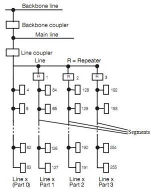
Fig.1 Connection of repeaters on a bus line
Application Programs
The coupler can be programmed using ETS version 5 or later.
In the line/backbone coupler mode, download the application program “KNX Line Coupler”.
In the repeater mode, download the application program “KNX Line Repeater”.
Factory Commissioning State
When delivered from the factory:
The line coupler blocks all telegrams, since the filter table is not yet defined.
The manual operation timeout is set to 120 minutes.
The default physical address is 15.15.0.
2. Technical Specifications
Power Supply | Bus Main Line | 21-30V DC (device power supply |
Bus Sub Line | 21-30V DC | |
Bus Current | Main <10mA/30VDC; Sub: <5mA/30VDC | |
Bus Consumption | Main <300mW; Sub <150mW | |
Connections | KNX Main/Sub Line | Left bus connection terminal (Red/Black) |
Operation & Display | KNX Main Line LED | Green on: Normal Off: Error |
KNX Sub Line LED | Green on: Normal Off: Error or not connected | |
Traffic Main Line LED | Green: Bus traffic on main line Red(flashing): Traffic error on main line | |
Traffic Sub Line LED | Green: Bus traffic on sub line Red(flashing): Traffic error on sub line | |
GA LED (Routing group telegrams, configured via ETS parameter “Group telegrams main groups 0...13”) | Used as a Line Coupler: Green: Filter table active Red: Block Green + Red: Route all Off: Telegrams differ on main and sub lines | |
Used as a repeater: Green and Red: Route all | ||
PA LED (Routing physical address telegrams) | Green: Filter table active Red: Block Green + Red: Route all Off: Telegrams differ on main and sub lines | |
Programming/Running LED | Red: Assigning physical address Green (flashing): Device running normally | |
Programming Button | Assigning physical address | |
Function LED | Green: Manual override active Off: Manual override inactive | |
Function Button | Switch to manual override | |
Environmental Condition | Operating Temperature Storage Temperature Transport Temperature | –5°C to + 45°C –25°C to + 55°C –25°C to + 70°C |
Ambient | Humidity | <93%(non-condensing) |
Protection | IP 20 | |
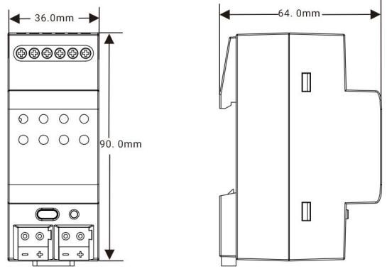
Dimensions | 36×90 ×64mm | |
Weight | 0.1KG | |
Housing | Plastic, beige | |
Design | Modular installation device for 35 mm DIN rail |
3. Dimensions and Operating Elements
3.1. Dimensions
3.2. Operating Elements
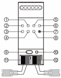
①Traffic Main Line LED | ④Traffic Sub Line LED | ⑦Function Button | ⑩Programming LED |
②KNX Main Line LED | ⑤PA LED | ⑧GA LED | ⑪KNX Main Line Terminal |
③KNX Sub Line LED | ⑥Function LED | ⑨Programming Button | ⑫KNX Sub Line Terminal |
NOTE:
The latest downloaded settings (parameters) and filter table are still available when switching from “Manual operation” to “Normal operation” .
4. Application
Application Program | Max. Number of Communication Objects | Max. Number of Group Addresses | Max. Number of Associations |
KNX Line Coupler/Repeater | 0 | 0 | 0 |
4.1. Coupler
When the coupler receives a telegram addressed to a physical address(e.g., during commissioning), it compares the received address with its own and determines whether routing is required.
The coupler handles group telegrams according to its parameter settings. In normal operation (default settings), it only routes telegrams whose group addresses are listed in the filter table.
If a routed telegram does not receive a response, or if a bus device detects a transmission error, the coupler will retransmit the telegram. Retransmission behavior can be configured separately for each line using the parameters: “ Repetition of group telegrams ” , “Repetition of physical addressed telegrams” , and “Repetition of broadcast telegrams”. These parameters are typically left at their default settings.
4.2. Repeater
As a line repeater, the filter table is disabled. This means that telegrams are forwarded to all connected lines, regardless of whether they are processed on the respective line. It makes no difference whether the telegram originates within a line or is sent from the main line to a sub line via a line coupler.
If an error occurs during the transmission of a telegram with the physical address of a receiver, the line repeater can retransmit it. This behavior can be configured separately for each line segment using the parameter “Repetition of physical addressed telegrams” .
If the line repeater routes a group telegram but does not receive an acknowledgement, or if a bus device detects a transmission error, the repeater will retransmit the telegram. This can be set independently for the main line and sub line using the parameter” Repetition of group telegrams”.
5. Coupler/Repeater Parameter Settings in ETS
5.1. Parameter Interface “General”
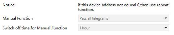
Fig.5.1 Parameter interface “General
Parameter “Manual Function”
Telegram routing configuration for the manual function.
Options:
Disabled
Pass all telegrams
Pass all Physical telegrams
Pass all Group telegrams
Parameter “Switch-off time for Manual Function”
Exit time from “manual operation” .
Options:
10 min
1 hour
4 hours
8 hours
NOTE:
The parameter “Transmit all” for Group or Physical telegrams is intended only for testing purposes and should not be used in normal operation.
5.2. Parameter Interface “Line-->Main Line”
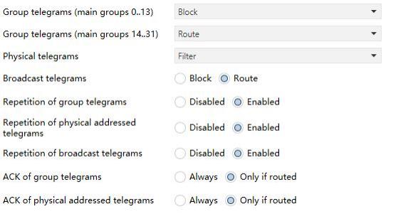
Fig.5.2 Parameter interface “Line-->Main line”
Parameter “Group telegrams: Main group 0..13”
Options:
Block: All group telegrams in main groups 0-13 are blocked.
Route: All group telegrams in main groups 0-13 are routed to the main line, regardless of the filter table. (For testing purposes only.)
Filter: Only group telegrams in main groups 0-13 that are included in the filter table are routed to the main line.
Parameter “Group telegram: Main group 14..31”
Options:
Block: All group telegrams in main groups 14-31 are blocked.
Route: All group telegrams in main groups 14-31are routed to the main line, regardless of the filter table. (For testing purposes only.)
Filter: Only group telegrams in main groups 14-31 that are included in the filter table are routed to the main line.
Parameter “Physical telegrams”
Options:
Block: No physical telegrams are routed to the main line.
Route: All physical telegrams are routed to the main line. (For test purposes only.)
Filter: Only telegrams addressed to this physical address are routed.
Parameter “Broadcast telegrams”
Options:
Block: No received broadcast telegrams are routed to the main line.
Route: All received broadcast telegrams are routed to the main line.
Parameter “Repetition of group telegram”
Options:
Disabled: Received group telegrams are not resent to the main line in case of a fault.
Enabled: Received group telegrams are resent up to three times in case of a fault.
Parameter “Repetition of physical addressed telegrams”
Options:
Disabled: Received physical addressed telegrams are not resent to the main line in case of a fault
Enabled: Received physical addressed telegrams are resent up to three times in case of a fault.
Parameter “Repetition of broadcast telegrams”
Options:
Disabled: Received broadcast telegrams are not resent to the main line in case of a fault
Enabled: Received broadcast telegrams are resent up to three times in case of a fault.
Parameter “ACK of group telegrams”
Options:
Always: An acknowledgement is generated for every group telegram received from the sub line.
Only if routed: An acknowledgement is generated only if the group telegram is routed to the main line.
Parameter “ACK of physical addressed telegrams”
Options:
Always: An acknowledgement is generated for every physical telegram received from the sub line.
Only if routed: An acknowledgement is generated only if the physical telegram is routed to the main line.
5.3. Parameter window “Main line-->Line”
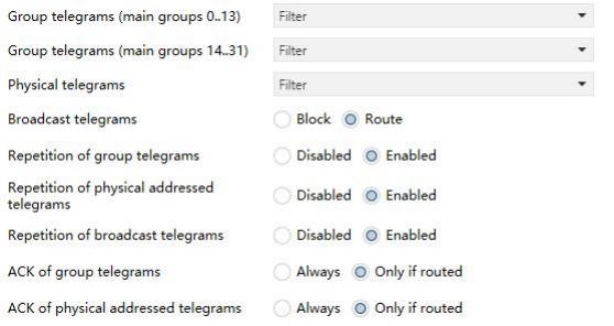
Fig.5.3 Parameter window “ Main line-->Linee”
Parameter “Group telegrams: Main group 0..13”
Options:
Block: All group telegrams in main groups 0-13 are blocked.
Route: All group telegrams in main groups 0-13 are routed to the sub line, regardless of the filter table. (For testing purposes only.)
Filter: Only group telegrams in main groups 0-13 that are included in the filter table are routed to the sub line.
Parameter “Group telegram: Main group 14..31”
Options:
Block: All group telegrams in main groups 14-31 are blocked.
Route: All group telegrams in main groups 14-31 are routed to the sub line, regardless of the filter table. (For testing purposes only.)
Filter: Only group telegrams in main groups 14-31 that are included in the filter table are routed to the sub line.
Parameter “Physical telegrams”
Options:
Block: No physical telegrams are routed to the sub line.
Route: All physical telegrams are routed to the sub line. (For testing purposes only.)
Filter: Only telegrams addressed to this physical address are routed.
Parameter “Broadcast telegrams”
Options:
Block: No received broadcast telegrams are routed to the sub line.
Route: All received broadcast telegrams are routed to the sub line.
Parameter “Repetition of group telegram”
Options:
Disabled: Received group telegrams are not resent to the sub line in case of a fault.
Enabled: Received group telegrams are resent up to three times in case of a fault.
Parameter “Repetition of physical addressed telegrams”
Options:
Disabled: Received physical addressed telegrams are not resent to the sub line in case of a fault
Enabled: Received physical addressed telegrams are resent up to three times in case of a fault.
Parameter “Repetition of broadcast telegrams”
Options:
Disabled: Received broadcast telegrams are not resent to the sub line in case of a fault
Enabled: Received broadcast telegrams are resent up to three times in case of a fault.
Parameter “ACK of group telegrams”
Options:
Always: An acknowledgement is generated for every group telegram received from the main line.
Only if routed: An acknowledgement is generated only if the group telegram is routed to the sub line.
Parameter “ACK of physical addressed telegrams”
Options:
Always: An acknowledgement is generated for every group telegram received from the main line.
Only if routed: An acknowledgement is generated only if the group telegram is routed to the sub line.