The “Room thermostat” parameter page (see Figure 5.10.1) is used to configure basic thermostat settings. It supports three device control modes: Air Conditioning, Floor Heating, and Ventilation.
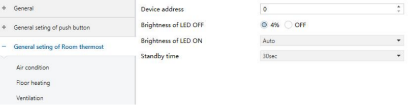
Figure 5.10.1 "General setting of Room thermostat" Interface
Device address
Sets the panel address. The default value is 10.
NOTE:
This function is currently unavailable, so the panel address cannot be set.
Brightness of LED OFF
Sets the brightness of the LED indicator when the touch button is not pressed.
Options:
4%
OFF
Brightness of LED ON
Sets the LED brightness when the touch button is pressed.
Options:
Auto
35%
45%
55%
65%
75%
85%
Standby time
Sets the time before the panel enters standby mode.
Options:
30 sec
1 min
2 min
3 min
4 min
5 min
Disable
5.10.1 Parameter Setting Interface “Air-condition”
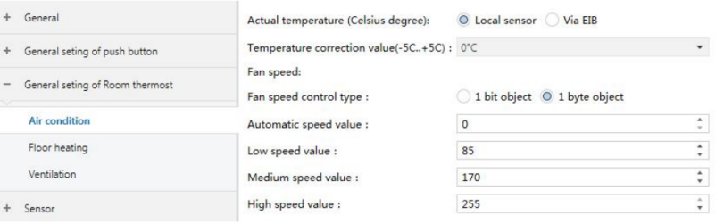
Figure 5.10.2 "Air-condition" Interface
Actual temperature (Celsius degree)
Defines the source of the actual ambient temperature used for air-conditioning control. Unit: °C.
Options:
Local sensor
Via EIB
Temperature correction value
Sets the calibration offset for the selected temperature source.
Range: –5 °C to +5 °C (step: 0.5 °C)
Options:
-5
4.5
-4
-3.5
……
3
3.5
4
4.5
5
Fan speed control type
Defines the data type of the fan speed control object.
Options:
1 bit object
1 byte object
The following parameters are available when "Fan speed control type" is set to “1 byte object”.
❖ Automatic speed value
Sets the control value and the feedback status value for automatic fan speed, with a range of 0–255.
❖ Low speed value
Sets the control value and the feedback status value for low fan speed, with a range of 0–255.
❖ Medium speed value
Sets the control value and the feedback status value for medium fan speed, with a range of 0–255.
❖ High speed value
Sets the control value and the feedback status value for high fan speed, with a range of 0–255.
Control mode type
Defines the data type of the air-conditioning mode control object.
Options:
1 bit object
1 byte object
The following parameters are available only when “1 byte object” is selected for the control mode type.
❖ Cooling value
Defines the control value and feedback value for cooling mode, with a range of 0–255.
❖ Heating value
Defines the control value and feedback value for heating mode, with a range of 0–255.
❖ Dehumidification value
Defines the control value and feedback value for dehumidification mode, with a range of 0–255.
❖ Fan value
Defines the control value and feedback value for Fan mode, with a range of 0–255.
Output control the relay actuator
Enables or disables control of the fan coil relay actuator.
Options:
disable
Enable
Temperature hysteresis (0.1°C)
Sets the hysteresis for heating or cooling output control.
Range: 1–200 (unit: 0.1 °C)
TIP:
Heating mode:
Stop heating when actual temperature T ≥ setpoint + hysteresis
Start heating when actual temperature T < setpoint – hysteresis
Example (hysteresis = 1 K, setpoint = 25 °C):
Heating stops above 26 °C and starts below 24 °C
Between 24 °C and 26 °C, the previous state is maintained.
Cooling mode:
Start cooling when actual temperature T > setpoint + hysteresis
Stop cooling when actual temperature T ≤ setpoint – hysteresis
Example (hysteresis = 1 K, setpoint = 25 °C):
Cooling starts above 26 °C and stops below 24 °C
Between 24 °C and 26 °C, the previous state is maintained.
NOTE:
When using two-point control, a hysteresis temperature must be set. Consider the following:
Small hysteresis: More stable temperature, but frequent control value transmissions increase bus and device load.
Large hysteresis: Fewer switching actions, but reduced comfort and control accuracy.
Fan Automatic Control Parameters
Fan output control type
Defines the fan speed switching conditions under two-point control.
The controller determines the fan state or speed based on the temperature difference between the actual temperature and the setpoint:
Cooling: Temperature difference = Actual temperature – Setpoint
Heating: Temperature difference = Setpoint – Actual temperature
Fan OFF & Low speed Temp Difference [1…200] (0.1°C)
Defines the temperature difference threshold between fan OFF and low speed. If the temperature difference ≥ this set value, the fan runs at low speed. If the difference < this set value, the fan is OFF.
Options: 1…200
Fan Low & Medium speed Temp Difference [1…200] (0.1°C)
Defines the temperature difference threshold for switching the fan to medium speed. If the temperature difference is ≥ this value, the fan runs at medium speed.
Options: 1…200
Fan Medium & High speed Temp Difference [1…200] (0.1°C)
Defines the temperature difference threshold for switching the fan to high speed. If the temperature difference is ≥ this value, the fan runs at high speed.
Options: 1…200
Fancoil Temp hysteresis [1…200] (0.1°C)
Sets the hysteresis value for temperature difference to prevent unnecessary fan actions near threshold values.
Options: 0…200
TIP:
No hysteresis. The fan switches speed immediately once the threshold is reached.
For example, if the hysteresis is 0.5 °C and the defined temperature difference is 1 °C:
The upper temperature difference = defined value + hysteresis = 1.5 °C
The lower temperature difference = defined value – hysteresis = 0.5 °C
When the temperature difference is between 0.5 °C and 1.5 °C, the fan does not change operation and maintains the previous state.
The fan changes its operating state only when the temperature difference is < 0.5 °C or ≥ 1.5 °C.
Minimum time in fan speed [0…65535]s
Defines the minimum running time before the fan can switch to another speed.
Speed changes are allowed only after this time elapses. If the current speed has already run long enough, switching occurs immediately.
Options: 0…200 (0 = No minimum time, but speed delay settings still apply.)
NOTE:
This parameter is only effective in Automatic mode.
Heating Output Mode Parameters
Control type
Sets the heating output control method.
Options:
Two-step (ON/OFF) control: Hysteresis value is required.
PWM control: PWM PI control.
Heating speed (For PI)
Sets the heating response speed by selecting PI control coefficients.
Options:
Lower
Low
Medium
Fast
Faster
PWM control object
Defines the PWM output data type for PI control.
Options:
PWM (1 bit)
PWM (1 byte)
The following parameter is available only when “PWM control object” is set to “PWM (1 bit)”.
❖ PWM period
Defines the PWM period (1–255 minutes).
Minimum PWM valve
Sets the minimum PWM output limit for heating valve control.
Options:
0%
5%
10%
15%
20%
25%
30%
35%
40%
Maximum PWM valve
Sets the maximum PWM output limit. Values above this limit are capped automatically.
Options:
60%
65%
70%
75%
80%
85%
90%
95%
100%
Cooling Output Mode Parameter Settings
Control type
Sets the cooling output control method.
Options:
Two-step (ON/OFF) control: Hysteresis value is required
PWM control: Uses PI control
Cooling speed (For PI)
Sets the cooling response speed by selecting PI control coefficients.
Options:
Lower
Low
Medium
Fast
Faster
PWM control object
Defines the PWM output data type for PI control.
Options:
PWM (1 bit)
PWM (1 byte)
The following parameter is available only when “PWM control object” is set to “PWM (1 bit)”.
❖ PWM period
Defines the PWM period (1–255 minutes).
Minimum PWM valve
Sets the minimum PWM output limit for cooling valve control.
Options:
0%
5%
10%
15%
20%
25%
30%
35%
40%
Maximum PWM valve
Sets the maximum PWM output limit. Values above this limit are capped automatically.
Options:
60%
65%
70%
75%
80%
85%
90%
95%
100%
5.10.2 Parameter Setting Interface “Floor heating”
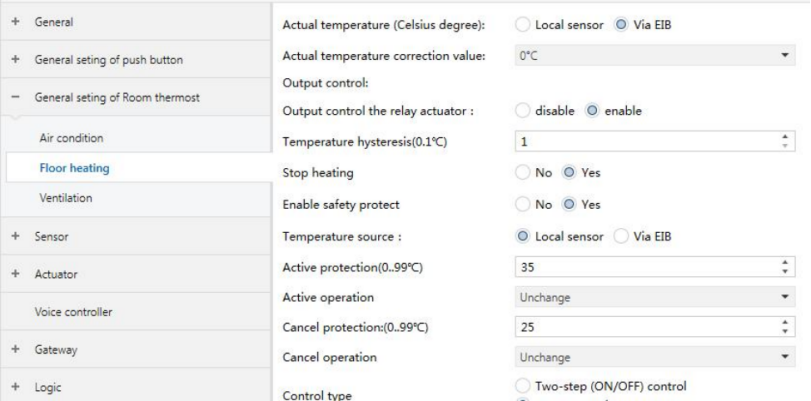
Figure 5.10.3 "Floor heating" Interface
Actual temperature (Celsius degree)
Defines the source of the actual ambient temperature used for floor heating output control.
Options:
Local sensor
Via EIB
Actual temperature correction value
Sets the correction offset for the acquired temperature value.
Range: −5 °C to +5 °C (step: 0.5 °C)
Options:
-5
-4.5
-4
-3.5
……
3
3.5
4
4.5
5
Output control the relay actuator
Enables or disables the electric heating valve actuator output.
Options:
Disable
Enable
Temperature hysteresis(0.1°C)
Sets the hysteresis value for two-step floor heating output control.
Range: 1–200 (unit: 0.1 °C)
Enable safety protect
Enables or disables overheat protection for floor heating actuators.
Options:
No
Yes
The following parameter is available only when “Enable safety protect” is enabled.
❖ Temperature source
Options:
Local sensor
Via EIB
Active protection (0–99°C)
Sets the temperature threshold that triggers overheat protection.
Range: 0–99 (Unit: °C)
Active operation
Defines the action performed when the protection temperature threshold is exceeded.
Options:
Unchange: Keep current status
OFF: Turn off floor heating
ON: Turn on floor heating
Cancel protection (0–99°C)
Sets the temperature threshold for canceling overheat protection.
Range: 0-99 (Unit: °C)
Cancel operation
Defines the action performed when overheat protection is canceled.
Options:
Unchange: Keep current status
OFF: Turn off floor heating
ON: Turn on floor heating
Floor Heating Output Control Parameters
Control type
Defines the floor heating valve output control method.
Options:
Two-step(ON/OFF) control: Requires setting a hysteresis value
PWM control: Uses PI control
Floor heating speed (For PI)
Sets the PWM output response speed by selecting PI control coefficients.
Options:
Lower
Low
Medium
Fast
Faster
PWM control object
Sets the data type of PWM output for PI control.
Options:
PWM(1bit)
PWM(1byte)
Then following parameter is available only when "PWM control object" is set to PWM(1bit).
❖ PWM period
Sets PWM period. Range: 1–255 minutes
Minimum PWM valve
Sets the minimum PWM output limit for valve control.
Options:
0%
5%
10%
15%
20%
25%
30%
35%
40%
Maximum PWM valve
Sets the maximum PWM output limit. Output values above this limit are capped automatically.
Options:
60%
65%
70%
75%
80%
85%
90%
95%
100%
5.10.3 Parameter Setting Interface “Ventilation”
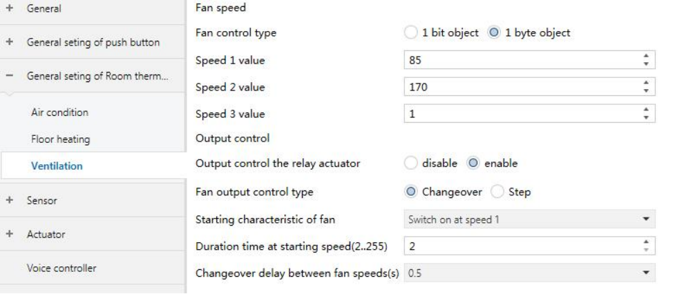
Figure 5.10.4 "Ventilation" Interface
Fan control type
Defines the object data type used for ventilation fan speed control.
Options:
1 bit object
1 byte object
The following parameters are available when the “Control type” is set to “1-byte object”.
❖ Speed 1 value
Defines the control or status feedback value for fan speed 1.
Range: 0–255
❖ Speed 2 value
Defines the control or status feedback value for fan speed 2.
Range: 0–255
❖ Speed 3 value
Defines the control or status feedback value for fan speed 3.
Range: 0–255
Output control the relay actuator
Enables or disables the ventilation fan actuator output.
Options:
Disable
Enable
Fan output control type
Defines the fan output switching method.
Options:
Changeover: Reverse switching
Step: Step switching
Starting characteristic of fan
Defines the fan speed after power-on. The speed levels correspond to the configured Speed X Value.
Options:
Switch on at speed 1
Switch on at speed 2
Switch on at speed 3
Duration time at starting speed
Defines how long the fan runs at the default speed after power-on.
Range: 2–255
Unit: seconds
Changeover delay between fan speed
Defines the delay when switching from one fan speed to another.
Unit: seconds
Options:
0.5
1
1.5
2
2.5
3
3.5
4
4.5
5
5.5
6
6.5
7
7.5
8
8.5
9
9.5
10