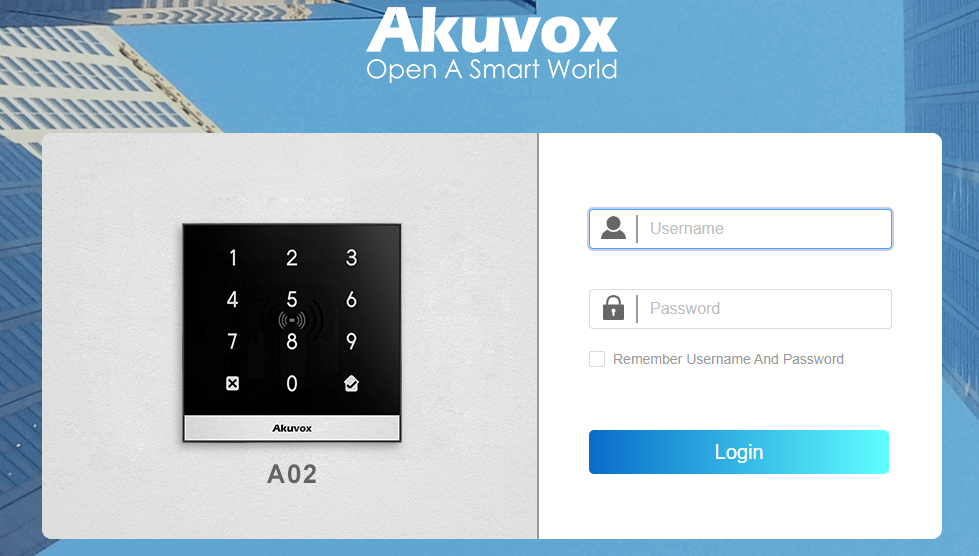
Akuvox A01/A03 Access Control Terminal Administrator Guide 202306
- 09 Nov 2023
- Print
- DarkLight
- PDF
Akuvox A01/A03 Access Control Terminal Administrator Guide 202306
- Updated on 09 Nov 2023
- Print
- DarkLight
- PDF
Article Summary
Share feedback
Thanks for sharing your feedback!
 About This Manual
Thank you for choosing the Akuvox A0X access control terminal. This manual is intended for the administrators who need to properly configure the access control terminal. This manual is written based on firmware version: 101.30.4.10/103.30.4.10, and it provides all the configurations for the functions and features of A01 and A03 access control terminals. Please visit the Akuvox forum or consult technical support for any new information or the latest firmware.
Introduction of Icons and Symbols
Note:
- Informative information and advice from the efficient use of the device.
Tip:
- Useful information for the quick and efficient use of the device.
Related Documentation
You are advised to refer to the related documents for more technical information via the link below:
https://knowledge.akuvox.com
Product Overview
Akuvox Access control terminals A01 and A03 incorporate a door controller and an RIFD reader in one standalone device, thus saving your solution costs. Equipped with a card reader (125kHz and 13.5MHz) which is currently capable of handling a majority of cards in wide use. A0X is designed to provide you with greater flexibility and security than those traditional access control systems. A0X access control terminal applies to residential buildings, office buildings, and their complex.
Change Log
The change log will be updated here along with the changes in new software version.
Model Specification

Introduction to Configuration Menu
- Status: this section gives you basic information such as product information, Network Information, and log related configurations such as access logs and so on.
- Network: this section covers LAN port setting.
- Access Control: this section covers relay, input, web relay, card setting, keypad and so on.
- Directory: this section includes access schedule management and user management.
- Device: this section includes light, Wiegand, lift control, and audio.
- Setting: this section deals with relay schedule, security notification settings, web relay, time, action, and HTTP API setting.
- System: this section covers firmware upgrade, device reset, reboot, configuration file auto-provisioning, system log and PCAP, password modification as well as device backup.
Tool selection
Akuvox has many configuration tools for you to set up devices more conveniently. Here we list some common tools, please contact your administrator to get the tool if you need them.
- ACMS: ACMS (Access Control Management System) is designed with an idea that personnel, device, access control, personnel attendance, and shift schedule, etc.
- Akuvox Upgrade tool: upgrade Akuvox devices in batch on a LAN (Local Area Network).
- Akuvox PC Manager: distribute all configuration items in batch on a LAN.
- IP Scanner: it is used to search Akuvox device IP addresses on a LAN.
Access the Device
Before configuring device, please make sure the device is installed correctly and connects to a normal network. Using the Akuvox IP scanner tool to search the device IP address in the same LAN. Then use the IP address to log in to the web browser by user name and password admin and admin.
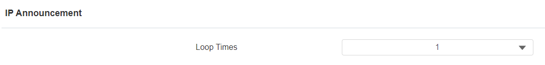
You can obtain the IP address by pressing the Reset button at the back of the device. And you can also set the number of IP number announcement (1-5 times) if needed. You can go to Device > Audio > IP Announcement.
Tip
- You can also obtain the device IP address using the Akuvox IP scanner to log in to the device web interface. Please refer to the URL below for the IP scanner application:https://knowledge.akuvox.com/v1/docs/en/how-to-obtain-ip-address-via-ip-scanner?highlight=IP%20Scanner
Note
- Google Chrome browser is strongly recommended.
- The Initial username and password are admin and please be case-sensitive to the user names and passwords entered.
Time Setting
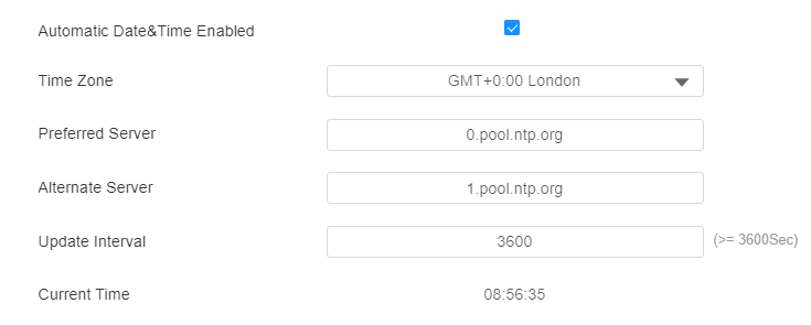
Time setting on the web interface allows you to set up time and date manually while allowing you to use the NTP server address that you obtained to automatically synchronize your time and date. And when your time zone is selected, the device will automatically notify the NTP server of its time zone so that the NTP server can synchronize the time zone setting in your device. To configure the configuration on the device web Setting > Time interface.

Parameter Set-up:
- Automatic Date&Time Enabled: if enabled, the device will update the time automatically via the NTP server (Network Time Protocol). Disable it if you want to set up the time manually.
- Time Zone: select the specific time zone based on where the device is used. The default time zone is GMT+0:00.
- Preferred Server: enter the primary NTP server address you want to update the time with. The default NPT server address is 0.pool.ntp.org.
- Alternate Server: enter the backup NPT server address you want to update the time with when the primary one failed.
- Update Interval: set the time update interval. For example, if you set it as 3600s, then the device will send a request to the NPT server for the time update once every 3600second.
- Current Time: display the current device time.
- Date/Time: set the date and time for the device manually when you disable the automatic date and time service.
Note
- You can only set the NTP-related parameter after you enable the automatic date and time.
Brightness Setting
If you want to brighten up the brightness in order to see the card reader at greater ease in an environment with higher light intensity, you need to set up the related parameters in the web Device > Light > Light of Swiping Card Area.
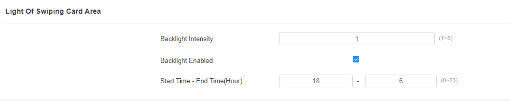
Parameter Set-up:
- Backlight Intensity: adjust the backlight intensity, the bigger value, the brighter backlight.
- Backlight Enabled: enable the card reader LED lighting if needed.
- Start Time - End Time (H): enter the time span for the LED lighting to be valid, e.g., if the time span is from 18-22 it means the LED light will stay on during the time span from 6:00 pm to 10:00 pm in one day (24 hours).
Volume and Tone Configuration
Volume and tone configuration in access control terminal refers to tamper alarm volume, voice prompt volume and open-door tone configuration. Moreover, you can upload the tone you like to enrich your personalized user experience.
Volume Configuration
You can configure the Mic volume according to your need for open-door notification. Moreover, you can also set up the tamper alarm volume when unwanted removal of the access control terminal occurs. To configure the configuration on web Device > Audio > Volume Control interface.

Parameter Set-up:
- Tamper Alarm Volume: set the tamper alarm volume from 0-15 according to your need. The default volume is 8.
- Voice Prompt Volume: set the voice prompt volume from 0-15 according to your need. The default volume is 8.
- Keypad Volume: adjust the volume of the keypad. The default volume is 8.
Upload Open Door Tone
You can upload the tone for open door failure and success on the device web interface. To upload the tones, go to Device > Audio > Open Door Tone Setting interface.

Parameter Set-up:
- Open Door Tone Enabled: enable it before you can apply the open door tone.
Note
- The open door tone file should be in .wav format and the file size should be smaller than 200KB.
Network Setting
You can configure the default DHCP mode (Dynamic Host Configuration Protocol) and static IP connection. Moreover, you can set up an IP address, Subnet Mask, Default Gateway, LAN DNS1 & LAN DNS2. To configure the configuration on web Network > Basic > LAN Port interface.
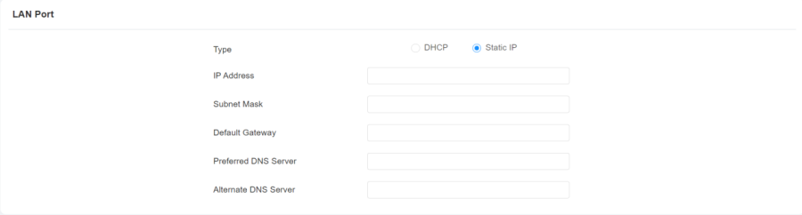
Parameter Set-up:
- DHCP: select the DHCP mode by checking off the DHCP box. DHCP mode is the default network connection. If the DHCP mode is selected, then the access control terminal will be assigned by the DHCP server with IP address, subnet mask, default gateway, and DNS server address automatically.
- Static IP: select the static IP mode by checking off the Static IP check box. When static IP mode is selected, then the IP address, subnet mask, default gateway, and DNS servers address must be manually configured according to your actual network environment.
- IP Address: set up the IP Address if the static IP mode is selected.
- Subnet Mask: set up the subnet mask according to your actual network environment.
- Default Gateway: set up the correct gateway default gateway according to the IP address of the default gateway.
- Preferred/Alternate DNS: set up DNS1/ DNS2 (Domain Name Server) according to your actual network environment. DNS1 is the primary DNS server address while the DNS2 is the secondary server address, and the access control terminal connects to the DNS2 server when the primary DNS server is unavailable.
Relay Setting
You can configure the relay switch(es) for door access on the web interface.
Relay switch setting
To configure the configuration on web Access Control > Relay > Relay interface.

Parameter Set-up:
- Trigger Delay (Sec): set the relay trigger delay timing (ranging from 0-10 Sec). For example, if you set the delay time as 5 sec. then the relay will not be triggered until 5 seconds after you press the unlock tab.
- Hold Delay (Sec): set the relay hold delay timing (ranging from 1-10 Sec). For example, if you set the hold delay time as 5 Sec. then the relay will be delayed for 5 after the door is unlocked.
- Relay Status: relay status is low by default which means normally closed (NC). If the relay status is high, then it is in normally open status (NO).
- Relay Name: name the relay switch according to your need. For example, you can name the relay switch according to where the relay switch is located for convenience.
Note
- Only the external devices connected to the relay switch need to be powered by power adapters as the relay switch does not supply power.
Web Relay Setting
In addition to the relay that is connected to the access control terminal, you can also control the door access using the network-based web relay on the device and on the device web interface.
Configure Web Relay on the Web Interface
Web relay needs to be set up on the web interface where you are required to fill in such information as relay IP address, password, and web relay action before you can achieve door access via web relay. To configure the configuration on web Access Control > Web Relay interface.


Parameter Set-up:
- Type: select your web relay type.
- Disabled: if it is selected, only the local relay will be triggered for the door opening.
- Web relay: if it is selected, only the web relay will be triggered for the door opening.
- Local Relay + Web relay: if it is selected, both the local relay and web relay will be triggered for the door opening. In the DTMF code door opening, if the web relay and local relay share the same DTMF code, the local relay will be triggered first.
- IP Address: enter the web relay IP address provided by the web relay manufacturer.
- User Name: enter the User name provided by the web relay manufacturer.
- Password: enter the password provided by the web relay manufacturer. The password is authenticated via HTTP and you can define the passwords using HTTP get in Action.
- Web Relay Action: enter the specific web relay action command provided by the web manufacturer for different actions by the web relay. http://admin:admin@192.168.1.2/state.xml?relayState=2.
After the web relay is set up, you can configure the specific web relay to be triggered based on the relay location for the door access. To configure the configuration on web Directory > User > Access Setting interface. You need to click the +Add tab to turn to the Access Setting interface.

Door Access Schedule Management
You are required to configure and make a schedule for the user-based door access via RF card, Private PIN.
Configure Door Access Schedule
You can create door access schedules so that they can be later conveniently applied to the door access control intended for individual users or a group of users created. Moreover, you can edit your door access schedule if needed.
Manage Relay Schedule
Set the corresponding relay always open at a specific time. This feature is designed for some specific scenarios, for example, the time after school, or for morning work time. To do the configuration on the web Access Control > Relay > Relay Schedule interface.

Parameter Set-up:
- Relay ID: choose the relay you need to set up.
- Schedule Enable: enable the relay schedule.
Create Door Access Schedule
You can create the door access schedule on a daily or weekly basis, and you can also create a schedule that allows you to plan for a longer period of time in addition to running the door access schedule on a daily or monthly basis. To configure the configuration on web Setting > Schedule interface.

To create a daily schedule, select Daily mode:
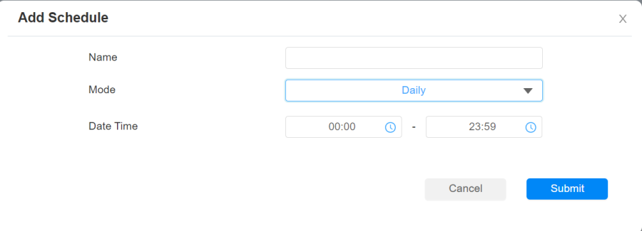
Parameter Set-up:
- Mode: select daily schedule.
- Name: enter the daily schedule name.
- Date Time: set up the time schedule for the validity of the door access during the day.
To create a daily schedule, select Weekly mode:
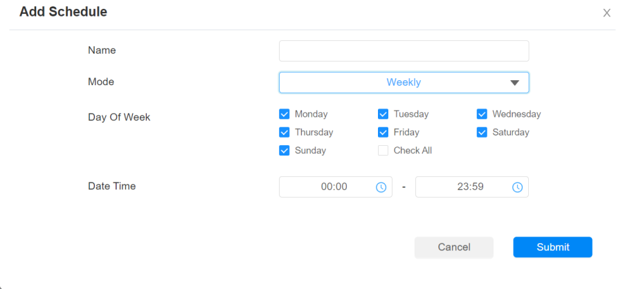
Parameter Set-up:
- Day of Week: select the day(s) on which door access can be valid on a weekly.
To create a longer period schedule:
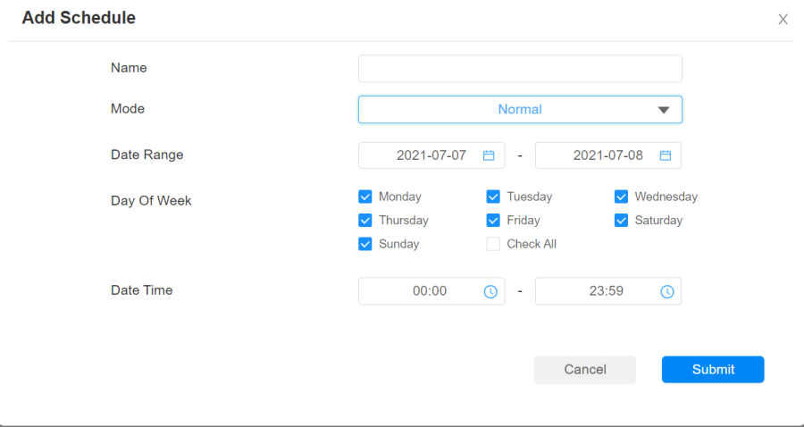
Parameter Set-up:
- Start Date- End Date: set the date range of the validity of the door access.
Import and Export Door Access Schedule
In addition to creating door access schedules separately, you can also conveniently import or export the schedules in order to maximize your door access schedule management efficiency. To configure the configuration on web Setting > Schedule interface.
Note
- It only supports .xml format files for importing and exporting the schedule.
Door Unlock Configuration
A0X access control terminal offers you three types of door access via RF card. You can configure them on the web interface. Moreover, you can import or export the configured files including access control information.
Configure RF Card for Door Unlock
Configure RF Card on the Web Interface
To configure the configuration on web Directory > User, then click + Add to go to RF card.


Note
- RF card with 13.56 MHz and 125 kHz can apply to the access control terminal for the door access.
Configure RF Card Code Format
If you want to integrate with the third-party intercom system in terms of RF card door access, you can change the RF card code format to be identical with that applied in the third-party system. To configure the configuration on the web Access Control > Card Setting >RFID interface.

Parameter Set-up:
- IC/ID Card Display Mode: select the card format for the ID Card for the door access among five format options: 8H10D; 6H3D5D(W26); 6H8D; 8HN; 8HR, and 8HR10D. The card code format is 8HN by default in the access control terminal.

Unlock by NFC
NFC (Near Field Communication) is a popular way for door access. It uses radio waves for data transmission interaction. A0X can be unlocked by NFC. You can keep the mobile phone closer to the door phone for door access. To configure the configuration on web Access Control > Card Setting > Contactless Smart Card interface.

Note
- NFC feature is only supported by Android telephones.
Unlock by HTTP Command on Web Browser
You can unlock the door remotely without approaching the device physically for door access by typing in the created HTTP command (URL) on the web browser to trigger the relay when you are not available by the door for door opening. To configure the configuration on web Access Control > Relay > Open Relay Via HTTP interface.
Parameter Set-up:
- Enable: enable the HTTP command to unlock function by clicking on Enable field.
- UserName: enter the user name of the device web interface, for example, Admin.
- Password: enter the password for the HTTP command. For example, 12345. Please refer to the following example: http://192.168.35.127/fcgi/do?action=OpenDoor&UserName=admin&Password=12345&DoorNum=1
Note
Unlock by Exit Button
When you need to open the door from inside using the exit button installed by the door, you can configure the access control terminal Input to trigger the relay for the door access. To configure the configuration on web Access Control > Input interface.
Parameter Set-up:
- Trigger Electrical Level: select the trigger electrical level options between High and Low according to the actual operation on the exit button.
- Action to execute: set actions to be triggered by the input. Email and HTTP URL actions are supported.
- HTTP URL: to set HTTP URL.
- Action Delay: set the action delay timing (ranging from 1-300 Sec). For example, if you set the delay time as 5. then the action will not be triggered until 5 seconds after the input status changes.
- Execute Relay: set up relays to be triggered by the input.
- Door Status: display the status of the input signal.
Unlock by Bluetooth
You can also gain door access by mobile phone with Bluetooth which is used together with Akuvox MobileKey App now. You can use the mobile phone closer to the access control terminal with hand-free mode for the door access.
Note
- Only A03 supports this feature.
- You can download the App from Google Play or App Store.
- Please refer to https://youtu.be/2ji9fQfxu2M and https://youtu.be/GvBvyXRDhh4 about using this feature.
You can enable BLE on Hardware>BLE.

Parameter Set-up:
- Enabled: this feature is enabled by default. You can disabled it if it is unnecessary.
- Open Door Interval(Sec): select the time interval between the every two Bluetooth door accesses.
- Authentcation Code Valid Time: for the security, you can setup the authentication code valid time to avoid codes being paired indefinitely. The time can be set up from 1h to 24h.
You can set up on Directory>User, click Add to enter BLE Setting interface.
Parameter Set-up:
- Authentication Code: click Generate to create a paring code for the App. The app will using this code to match with A03.
- Status: Shows whether the current authentication code has been paired with the app.
- Paring Valid Until: display the current pairing validity period of this code.
Security
Tamper Alarm Setting
The tamper alarm function serves as a protection against any unauthorized removal of the devices by triggering off the temper alarm on the device. To configure the configuration on web System > Security > Tamper Alarm interface.
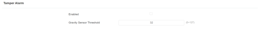
Parameter Set-up:
- Enabled: enable the anti-theft alarm function.
- Gravity Sensor Threshold: set the threshold for gravity sensory sensitivity. The lower the value is, the more sensitive the sensor will be. The gravity sensor value is 32 by default.
Security Notification Setting
Email Notification Setting
If you want to receive the security notification via E-mail, you can configure the E-mail notification on the web interface properly. To configure the configuration on web Setting > Action > Email Notification interface.

Parameter Set-up:
- Sender's Email Name: enter the name of the email sender.
- Sender's Email address: enter the sender's email address from which the email notification will be sent out.
- Receiver's Email address: enter the receiver's email address.
- Receiver's Email Name: enter the name of the email receiver.
- SMTP Server Address: enter the SMTP server address of the sender.
- Port: enter the port number from which the email is sent out.
- SMTP User Name: enter the SMTP user name, which is usually the same as the sender's email address.
- SMTP Password: configure the password of the SMTP service, which is the same as the sender's email address.
- Email Subject: enter the subject of the email.
- Email Content: compile the email contents according to your need.
- Email Test: click to test if the email can be sent and received.
High Security Mode
High security mode is designed to enhance the security, for example, it optimizes the password storage method.
Please note that once the mode is enabled, it is not allowed to downgrade the device from the version with the mode to an old one without it.
To configure this feature on the web: System>Security>High Security Mode

Important Notes
1. This mode is disabled by default when the device is upgraded to a new version with high security from an older version without the mode. However, if the device is reset to its factory settings, the mode is enabled by default.
2. Enabling this mode will make the old version tools unusable. To continue using them, you must upgrade them to the following versions.
- PC Manager: 1.2.0.0
- IP Scanner: 2.2.0.0
- Upgrade Tool: 4.1.0.0
- SDMC: 6.0.0.34
3. The supported HTTP format varies depending on whether high secure mode is enabled or disabled.
- When the mode is turned on, the device only supports new HTTP formats for door opening.
- http://username:password@deviceIP/fcgi/OpenDoor?action=OpenDoor&DoorNum=1
- http://deviceIP/fcgi/OpenDoor?action=OpenDoor&DoorNum=1
- When the mode is off, the device supports the above two new formats as well as the old one:
- http://deviceIP/fcgi/do?action=OpenDoor&UserName=username&Password=password&DoorNum=1
4. It is not allowed to import/export tgz. format configuration files between a new version device and an old version device without high security mode.
Access Log
If you want to search and check on door access history, you can search and check the door logs on the device web Status > Access Log interface.
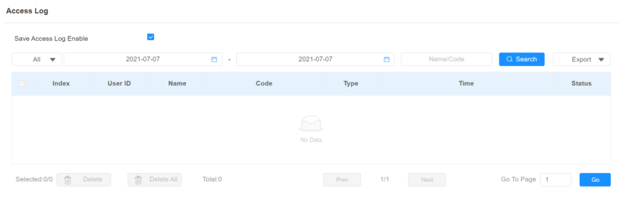
Parameter Set-up:
- Save Access Log Enabled: tick the check box to turn on or turn off the door log function.
- Status: select between Success and Failed options to search for successful door accesses or failed door accesses.
- Time: select the specific time span of the door logs you want to search, check or export.
- Name/Code: select the Name and Code options to search the door log by the name or by the PIN code.
- Door ID: displays the door name.
- Type: display the access type like card or HTTP.
Debug
System Log for Debugging
System log in the access control terminal can be used for debugging purposes. If you want to export the system out to a local PC or to a remote server for debugging, you can set up the function on the web System > Maintenance > System Log interface.

Parameter Set-up:
- LogLevel: select log levels from 1 to 7 levels. You will be instructed by Akuvox technical staff about the specific log level to be entered for debugging purpose. The default log level is 3, the higher the level is 5, the more complete the log is 7.
- Export Log: click the Export tab to export the temporary debug log file to a local PC.
- Remote System Log Enabled: select Enable or Disable if you want to enable or disable the remote system log.
- Remote System Server: enter the remote server address to receive the device log. And the remote server address will be provided by Akuvox technical support.
Remote Debug Server
You can set up remote debug server so that Akuvox technical team will be able to obtain the log remotely for debugging. To configure the server, go to System > Maintenance > > Remote Debug Server.

Parameter Set-up:
- Enabled: enable the debug server before debugging.
- Connect Status: displays the remote debug server connection status.
- IP Address: enter the remote debug server IP address. Please ask Akuvox technical team for the server IP address.
- Port: type in the remote debug server port.
PCAP for Debugging
PCAP in access control terminal is used to capture the data package going in and out of the devices for debugging and troubleshooting purpose. You can set up the PCAP on the device web System > Maintenance > PCAP interface properly before using it.

Parameter Set-up:
- Specific Port: select the specific ports from 1-65535 so that only the data packet from the specific port can be captured. You can leave the field blank by default.
- PCAP: click Start tab and Stop tab to capture a certain range of data packets before clicking Export tab to export the data packets to your Local PC.
- PCAP Auto Refresh Enabled: select Enable or Disable to turn on or turn off the PCAP auto fresh function. If you set it as "Enable" then the PCAP will continue to capture data packet even after the data packets reached its 50M maximum in capacity. If you set it as Disable the PCAP will stop data packet capturing when the data packet captured reached the maximum capturing capacity of 1MB.
Firmware Upgrade
Firmware of different versions for access control terminal can be upgraded on the device web System > Upgrade interface.

Note
- Firmware files should be in .rom format for the upgrade.
Backup
Configuration files can be imported to or exported out of the device to your local PC on the device web System > Maintenance > Others interface if needed.

Auto-provisioning
Configurations and upgrading on access control terminal can be done on the web interface via one-time auto-provisioning and scheduled auto-provisioning via configuration files, thus saving you from setting up configurations needed one by one manually on the access control terminal.
Provisioning Principle
Auto-provisioning is a feature used to configure or upgrade devices in batch via third-party servers. DHCP, PNP, TFTP, FTP, HTTPS are the protocols used by the Akuvox intercom devices to access the URL of the address of the third-party server which stores configuration files and firmware, which will then be used to update the firmware and the corresponding parameters on the access control terminal.

Configuration Files for Auto-provisioning
Configuration files have two formats for auto-provisioning. One is the general configuration files used for general provisioning and another one is MAC-based configuration provisioning.
The difference between the two types of configuration files is shown below:
- General configuration provisioning: a general file is stored in a server from which all the related devices will be able to download the same configuration file to update parameters on the devices. For example: r000000000083.cfg.
- MAC-based configuration provisioning: MAC-based configuration files are used for auto-provisioning on a specific device as distinguished by its unique MAC number. And the configuration files named with the device MAC number will be matched automatically with the device MAC number before being downloaded for the provisioning on the specific device.
Note
- If a server has these two types of configuration files, then IP devices will first access the general configuration files before accessing the MAC-based configuration files.
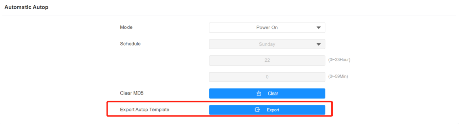
AutoP Schedule
Akuvox provides you with different Autop methods that enable the access control terminal to perform provisioning for itself at a specific time according to your schedule. To configure the configuration on web System > Auto Provisioning > Automatic Autop interface.

Parameter Set-up:
- Power On: select Power on if you want the device to perform Autop every time it boots up.
- Repeatedly: select Repeatedly, if you want the device to perform Autop according to the schedule you set up.
- Power On + Repeatedly: select Power On + Repeatedly if you want to combine Power On mode and Repeatedly mode that will enable the device to perform Autop every time it boots up or according to the schedule you set up.
- Hourly Repeat: select Hourly Repeat if you want the device to perform Autop every hour.
DHCP Provisioning Configuration
Auto-provisioning URL can also be obtained using DHCP option which allows the device to send a request to a DHCP server for a specific DHCP option code. If you want to use Custom Option as defined by users with option code (ranging from 128-255), you are required to configure DHCP Custom Option on the web interface. To set up DHCP AutoP with "Custom Option" and "Power on" mode. And export Autop Template to edit the configuration. Then set up DHCP Option on System > Auto Provisioning > DHCP Option interface.

Note
- The custom Option type must be a string. The value is the URL of the TFTP server.

Parameter Set-up:
- Custom Option: enter the DHCP code that matches the corresponding URL so that the device will find the configuration file server for the configuration or upgrading.
- DHCP Option 66: if none of the above is set, the device will automatically use DHCP Option 66 for getting the upgrade server URL. This is done within the software and the user does not need to specify this. To make it work, you need to configure the DHCP server for option 66 with the update server URL in it.
- DHCP Option 43: if the device does not get an URL from DHCP Option 66, it will automatically use DHCP Option 43. This is done within the software and the user does not need to specify this. To make it work, you need to configure the DHCP server for option 43 with the update server URL in it.
Note
- The general configuration file for the in-batch provisioning is with the format r0000000000xx.cfg. Taking A01 as an example, r000000000101.cfg (10 zeros in total), while the MAC-based configuration file for the specific device provisioning is with the format MAC_Address of the device.cfg, for example, 0C110504AE5B.cfg.
Static Provisioning Configuration
You can manually set up a specific server URL for downloading the firmware or configuration file. If an Autop schedule is set up, the access control terminal will perform the auto-provisioning at a specific time according to Autop schedule you set up. In addition, TFTP, FTP, HTTP, and HTTPS are the protocols that can be used for upgrading the device firmware and configuration. Download the Autop template first and set up Autop server on System > Auto Provisioning > Manual Autop interface.


Parameter Set-up:
- URL: set up TFTP, HTTP, HTTPS, and FTP server addresses for the provisioning.
- User Name: set up a user name if the server needs a user name to be accessed otherwise leave it blank.
- Password: set up a password if the server needs a password to be accessed otherwise leave it blank.
- Common AES Key: set up AES code for the intercom to decipher the general Auto Provisioning configuration file.
- AES Key (MAC): set up AES code for the intercom to decipher the MAC-based auto provisioning configuration file.
Note
- AES is one type of encryption, it should be configured only when the config file is encrypted with AES, otherwise, it leaves the field blank.
Note
Server Address format:
- TFTP: tftp://192.168.0.19/
- FTP: ftp://192.168.0.19/ (allows anonymous login)
- ftp://username:password@192.168.0.19/(requires a user name and password)
- HTTP: http://192.168.0.19/ (use the default port 80)
- http://192.168.0.19:8080/ (use other ports, such as 8080)
- HTTPS: https://192.168.0.19/ (use the default port 443)
Tip
- Akuvox does not provide user specified server.
- Please prepare TFTP/FTP/HTTP/HTTPS server by yourself.
Integration with Third Party Device
Integration via Wiegand
If you want to integrate the access control terminal with the third-party devices via Wiegand, you can configure the Wiegand on the web Device > Wiegand interface.

Parameter Set-up:
- Wiegand Display Mode: select Wigand Card code format among 8H10D; 6H3D5D; 6H8D; 8HN; 8HR; RAW.
- Wiegand Card Reader Mode: set the Wiegand data transmission format among three options: Wiegand 26, Wiegand 34, Wiegand 58. The transmission format should be identical between the access control terminal and the device to be integrated.
- Wiegand Transfer Mode: set the transfer mode between Input or Output if the access control terminal is used as a receiver, then set it as "Input" for the access control terminal and vice versa.
- Wiegand Input Data Order: set the Wiegand input data sequence between Normal and Reversed if you select Reversed then the input card number will be reversed and vice versa.
- Wiegand Output Data Order: set the Wiegand output data sequence between Normal and Reversed if you select Reversed then the input card number will be reversed and vice versa.
- Wiegand Output CRC Enable: tick to enable the parity check function to ensure that signal-based data can be transmitted correctly according to the established data transmission format.
Integration via HTTP API
HTTP API is designed to achieve a network-based integration between the third-party device with the Akuvox intercom device. You can configure the HTTP API function on the web Setting > HTTP API interface for the integration.

Parameter Set-up:
- HTTP API: select Enable or Disable to enable or disable the HPTT API function for the third-party integration. For example, if the function is disabled any request to initiate the integration will be denied and be returned HTTP 403 forbidden status.
- Authorization Mode: select among four options: None, WhiteList, Basic, Digest, and Token for authorization type, which will be explained in detail in the following chart.
- Username: enter the user name when Basic and Digest authorization mode is selected. The default user name is Admin.
- Password: enter the password when Basic and Digest authorization mode is selected. The default user name is Admin.
- 1st IP-5th IP: enter the IP address of the third-party devices when the Allowlist authorization is selected for the integration.
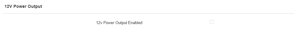
Power Output
Device can provide 12V power to Akuvox devices and third-party devices through Relay_Com1 and GND-OUT. To enable the power supply, go to Access Control > Relay > 12 Power Out.
Password Modification
Modify the Password
On the device web interface, you can set and change password for accessing the web System > Security > Web Password Modify interface. In addition, you can also select the user role when setting passwords.

Web Interface Automatic Log-out
You can set up the web interface automatic log-out timing, requiring re-login by entering the user name and the passwords for security purpose or the convenience of operation. To configure the configuration on web System > Security > Session Time Out interface.

Parameters Set-up:
- Session Time Out Value: if there is no operation over the time, you need to log in to the website again.
Action URL
Device allows you to set up specific HTTP URL commands that will be sent to the HTTP server for the predefined actions. Relevant actions will be initiated if there occur any changes in the relay status, input status, PIN code, and RF card access for security purpose. You can navigate to Setting > Actions URL.

Akuvox Action URL:
No | Event | Parameter format | Example |
1 | Make Call | $remote | Http://server ip/Callnumber=$remote |
2 | Hang Up | $remote | Http://server ip/Callnumber=$remote |
3 | Relay Triggered | $relay1status | Http://server ip/relaytrigger=$relay1status |
5 | Relay Closed | $relay1status | Http://server ip/relayclose=$relay1status |
6 | Input Triggered | $input1status | Http://server ip/inputtrigger=$input1status |
7 | Input Closed | $input1status | Http://server ip/inputclose=$input1status |
8 | Valid Code Entered | $code | Http://server ip/validcode=$code |
9 | Invalid Code Entered | $code | Http://server ip/invalidcode=$code |
10 | Valid Card Entered | $card_sn | Http://server ip/validcard=$card_sn |
11 | Invalid Car Entered | $card_sn | Http://server ip/invalidcard=$card_sn |
12 | Tamper Alarm Triggered | $alarm status | Http://server ip/tampertrigger=$alarm status |
For example: http://192.168.16.118/help.xml?mac=$mac:ip=$ip:model=$model:firmware=$firmware:card_sn=$card_sn
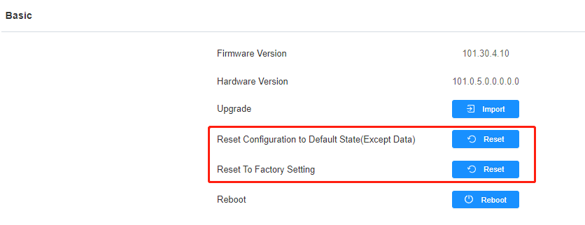
System Reboot and Reset
Reboot
If you want to restart the device, you can operate it on the device web System > Upgrade > Basic interface as well. Moreover, you can set up a schedule for the device to be restarted.

To set up the device restart schedule on web System > Auto Provisioning > Reboot Schedule interface.

Reset
You can select Reset To Factory Setting if you want to reset the device (deleting both configuration data and user data such as RF cards, face data and so on). Or, select Reset Configuration to Default State(Except Data)Reset, if you want to reset the device (retaining the user data). To reset the device, go to System > Upgrade.
Abbreviations
ACS: Auto Configuration Server
Auto: Automatically
AEC: Configurable Acoustic and Line Echo Cancelers
ACD: Automatic Call Distribution
Autop: Automatic Provisioning
AES: Advanced Encryption Standard
BLF: Busy Lamp Field
COM: Common
CPE: Customer Premise Equipment
CWMP: CPE WAN Management Protocol
DTMF: Dual Tone Multi-Frequency
DHCP: Dynamic Host Configuration Protocol
DNS: Domain Name System
DND: Do Not Disturb
DNS-SRV: Service record in the Domain Name System
FTP: File Transfer Protocol
GND: Ground
HTTP: Hypertext Transfer Protocol
HTTPS: Hypertext Transfer Protocol Secure Socket Layer
IP: Internet Protocol
ID: Identification
IR: Infrared
LCD: Liquid Crystal Display
LED: Light Emitting Diode
MAX: Maximum
POE: Power Over Ethernet
PCMA: Pulse Code Modulation A-Law
PCMU: Pulse Code Modulation µ-Law
PCAP: Packet Capture
PNP: Plug and Play
RFID: Radio Frequency Identification
RTP: Real-time Transport Protocol
RTSP: Real Time Streaming Protocol
MPEG: Moving Picture Experts Group
MWI: Message Waiting Indicator
NO: Normal Opened
NC: Normal Connected
NTP: Network Time Protocol
NAT: Network Address Translation
NVR: Network Video Recorder
ONVIF: Open Network Video Interface Forum
SIP: Session Initiation Protocol
SNMP: Simple Network Management Protocol
STUN: Session Traversal Utilities for NAT
SNMP: Simple Mail Transfer Protocol
SDMC: SIP Devices Management Center
TR069: Technical Report069
TCP: Transmission Control Protocol
TLS: Transport Layer Security
TFTP: Trivial File Transfer Protocol
UDP: User Datagram Protocol
URL: Uniform Resource Locator
VLAN: Virtual Local Area Network
WG: Wiegand
FAQ
Q1: How to obtain the IP address of the access control terminal?
A1: Using Akuvox IP Scanner to search Akuvox devices in the same LAN network.
Q2: What is the supported temperature range for A01?
A2: Working Temperature: -20°C ~ +55°C
Storage Temperature: -30°C ~ +70°C
Q3: Do Akuvox devices support Modbus protocol?
A3: No.
Q4: Do access control terminals support these card types? Prox, Legacy iClass, iClassSE, HID Mifare, HID DESFire, and HID SEOS
A4: Sorry, they are not supported. They need to be implemented via hardware modifications.
Contact Us
For more information about the product, please visit us at www.akuvox.com or feel free to contact us by
Sales email: sales@akuvox.com
Technical support email: support@akuvox.com
Telephone: +86-592-2133061 ext.7694/8162
We highly appreciate your feedback about our products.

Parameter Set-up:
- l Enabled: this feature is enabled by default. You can disabled it if it is unnecessary.
- l Open Door Interval(Sec): select the time interval between the every two Bluetooth door accesses.
- l Authentcation Code Valid Time: for the security, you can setup the authentication code valid time to avoid codes being paired indefinitely. The time can be set up from 1h to 24h.
You can set up on Directory>User, click Add to enter BLE Setting interface.
Was this article helpful?
-20190329_%E5%89%AF%E6%9C%AC.png)