The SR01 security relay improves access security by controlling door locks directly from indoors. Unlike traditional systems, where the lock is connected to the door phone’s relay, someone may smash up the door phone and break into the door for illegal purposes like burglary. SR01 can prevent such malicious break-ins because it is installed indoors and controls the door opening directly. In this case, even if the door phone is destroyed, the door cannot be opened.
The following devices with specific firmware versions or higher support connecting to SR01:
Model | Version | Model | Version |
|---|---|---|---|
S539 | 539.30.1.105 | S538 | 538.30.10.705 |
S532 | 532.30.1.19 | S535 | 535.30.10.233 |
X910 | 2910.30.10.240 | X912 | 912.30.1.78 |
X915 V2 | 2915.30.1.14 | X916 | 916.30.10.110 |
R20 V3 | 220.30.4.5 | R20 V5 | 320.30.4.2 |
R25 Series | 25.30.10.117 | R29 | Higher than 29.30.3.203 |
R28 | 28.30.10.5 | R27 V2 | 227.30.4.4 |
E18 | 18.30.4.29 | E16 V2 | 216.30.0.52 |
E16 | 116.30.8.5 | E12 | 12.30.2.110 |
E12 V2 | 312.30.2.109 | A01/A02 | 101.30.4.37 |
A03 | 103.30.4.9 | A05 | 105.30.4.10 |
A08 | 108.30.1.17 |
Wiring
You may refer to the following two videos for wiring.
Note
E12 has to be connected with SR01 in an exceptional way because it does not have RS485 ports.
It is NOT recommended to use such a connection due to security.
Connect Akuvox SR01 to Door Phone (with 12V Output)
Connect Akuvox SR01 to Door Phone (via RS485)
Configuration on the Device Web Interface
Take the door phone X912 as an example.
Connect Akuvox SR01 to Door Phone (with 12V Output)
Use the device IP to log in to its web interface. The default username and password are admin.
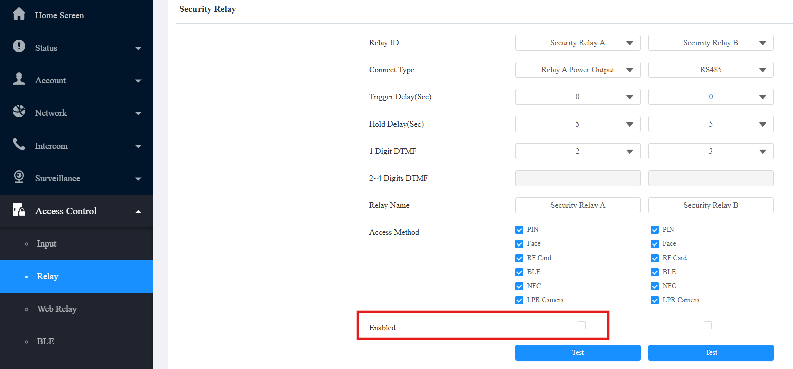
Go to Access Control > Relay > Security Relay.
Specify which relay is connected to the SR01 and check the Enabled box.
You can set the Trigger Delay and Hold Delay.
Trigger Delay: If you choose 5 seconds, the relay will be triggered 5 seconds after you press the Unlock tab. 0 means immediate trigger.
Hold Delay: If you choose 5 seconds, the relay will remain activated for 5 seconds after it is triggered.
Scroll down to 12V Power Output and select Security Relay A in Power Output Type.
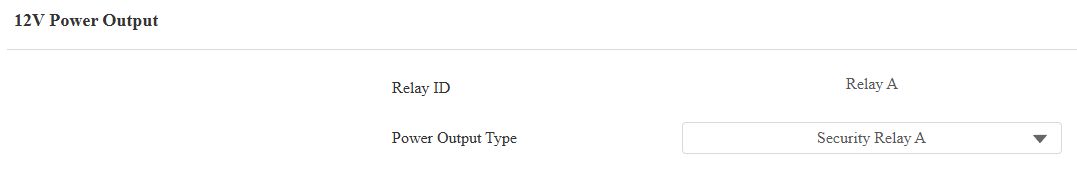
Click Submit to save the configuration.
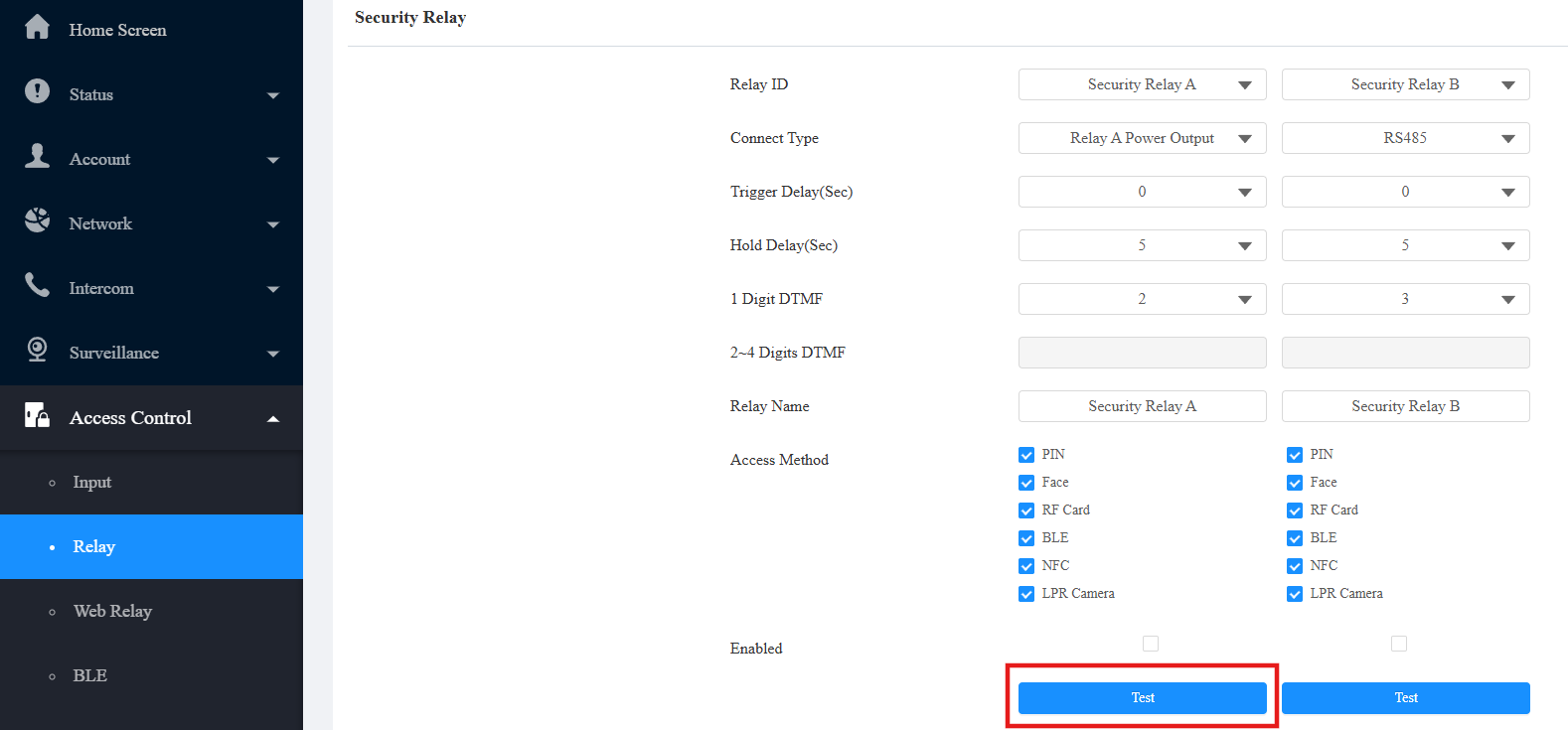
Run the test as shown in the video, or click Test of Security Relay A.
When the green light of SR01 is flashing quickly, SR01 and the door phone are pairing successfully.
Connect Akuvox SR01 to Door Phone (via RS485)
Use the device IP to log into its web interface. The default username and password are admin.
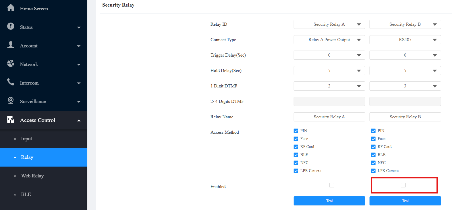
Go to Access Control > Relay > Security Relay.
Check the Enabled box of Security Relay B since the door phone and the security relay are connected via RS485 ports, and Security Relay B's server mode is RS485.
You can set up Trigger Delay and Hold Delay.
Trigger Delay: If you choose 5 seconds, the relay will be triggered 5 seconds after you press the Unlock tab. 0 means immediate trigger.
Hold Delay: If you choose 5 seconds, the relay will remain activated for 5 seconds after it is triggered.
Click Submit to save the configuration.
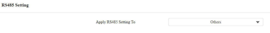
Go to Device > RS485 interface and set Apply RS485 Setting To to Others.
Note
After the security relay is configured, you need to add users and assign them credentials to open the SR01.
You may refer to Open Doors for adding users.
E18 does not support the Hold Delay option.
Upgrade SR01
You can upgrade SR01 on the device’s web interface when SR01 is connected via RS485.
Compatible models and versions(or higher):
X912: 912.30.11.49
R29: 29.30.10.432
X915V2: 2915.30.10.625
S538: 538.30.10.705
S539: 539.30.10.507
A08: 108.30.11.226
Before upgrading, make sure the device is connected properly and powered on.
Go to the Device > RS485 interface and set Apply RS485 Setting To to Others.
Click Connect to detect the SR01.
Click Upgrade to upload the .rom file. Please contact the Akuvox tech support for the firmware.
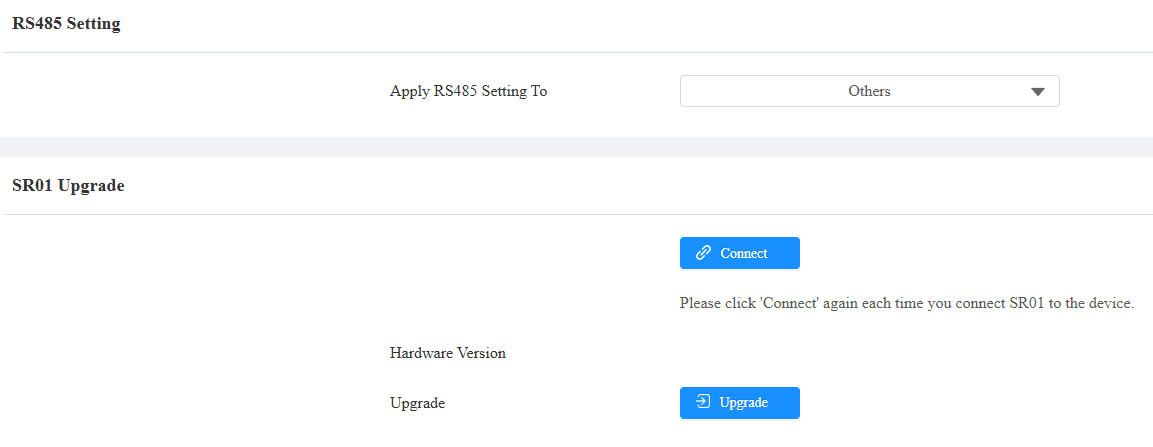
“Upgrade Successful” will display after the upgrade.
Apply Relay Schedule to SR01
The relay schedule can keep the SR01 open at a scheduled time.
Note
The following device models with specific firmwares or higher support this feature:
X912: 912.30.11.57
E12: 312.30.10.229
R20 Series: 320.30.11.37
R28: 228.30.10.213
X915V2: 2915.30.10.625
A08: 108.30.11.226
The SR01’s version should be V15 or higher. Click here to download the firmware and refer to Upgrade SR01 for upgrading it.
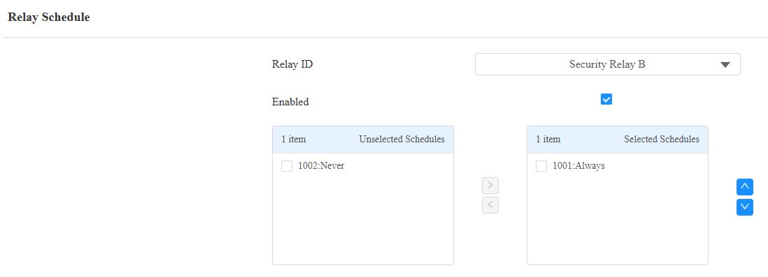
Go to the Access Control > Relay > Relay Schedule interface.
Check the Enabled box and select the security relay.
Apply a schedule by moving it from the left to the right box.
Configuration on SmartPlus Platform
When the device is connected to the SmartPlus Cloud, you can set up SR01 on the SmartPlus platform.
Single-Family Projects
Log in to the SmartPlus platform with an installer account.
Click Single-Family Sites on the dashboard.
Click
 of the target user. Click New to add a device or click
  to modify a device.
Find Add Security Relay and click it.
Customize the relay name. Select the DTMF code and access methods.
Note
The DTMF code should be the same as that on the device’s web interface.
To check it, navigate to the Access Control > Relay > Security Relay interface.

Community Projects
Log in to the SmartPlus platform with an installer account.
Click Communities on the dashboard and navigate to the target community by clicking
 .
.Navigate to where the device is installed and click Intercom Devices.
Click New to add a device or click
to modify a device.Find Add Security Relay and click it.
Customize the relay name. Select the DTMF code and access methods.
Note
The DTMF code should be the same as that on the device’s web interface.
To check it, navigate to the Access Control > Relay > Security Relay interface.