Integration via Wiegand
The Wiegand feature enables the Akuvox device to act as a controller or a card reader.
Set it up on the web Device > Wiegand interface.
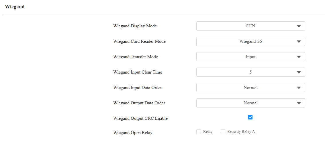
Wiegand Display Mode: Select the Wiegand card code format from the following options: 8H10D, 6H3D5D, 6H8D, 8HN, 8HR, 6H3D5D-R, 8HR10D, and RAW.
Wiegand Card Reader Mode: The transmission format should be identical between the door phone and the third-party device. It is automatically configured for Input Wiegand transfer mode.
Wiegand Transfer Mode:
Input: The device serves as a receiver.
Output: The device serves as a sender and can directly output the data, such as the card code.
Wiegand Input Clear Time: When the interval between entering passwords exceeds this time. All entered passwords will be cleared.
Wiegand Input Data Order: Set the Wiegand input data sequence between Normal and Reversed. If you select Reversed, then the input card number will be reversed.
Wiegand Output Data Order: Determine the sequence of the card data after the Wiegand conversion.
For example, if the card data is 0x11 0x22 0x33 0x44 0x55, it will be 0x33 0x44 0x55 after the Wiegand conversion(e.g., Wiegand 26). If Reversed is selected, the card data is 0x55 0x44 0x33.
ID Card Output Raw Bytes: This option is available when Wiegand Transfer Mode is Output. Select the output bytes of ID cards between 3 bytes and 4 bytes.
Wiegand Output CRC Enable: It is enabled by default for Wiegand data inspection. Disabling it may lead to integration failure with third-party devices.
Wiegand Out Verification: This feature is for checking the card validity when Output mode is selected. This feature requires you to assign the card code to a user on the Directory > User interface.
Card Entered Action: This option is available when Wiegand Transfer Mode is Output and Wiegand Out Verification is disabled. You can enter an HTTP command sent to a third-party HTTP server to verify the validity of the card.
Please refer to the HTTP formats: http://{server ip}/validcard=$card_sn; http://{server ip}/invalidcard=$card_sn.
Replace {server ip} with the HTTP server IP.
Wiegand Open Relay: Enable the relay to be triggered through Wiegand.
Note
Click here to view more information on Wiegand settings, including:
Akuvox devices work as Wiegand input/output.
Wiegand Card Reader Connection.
Facility Code Setting
A facility code is a unique number on access control cards. It identifies the device that issued the card.
When the Wiegand Transfer Mode is Output, you can set up the facility code on the Device > Wiegand interface.

Facility Code: The value ranges from 0 to 255. If filled in, the first two digits of the card number will be replaced by the code. If the code is less than 2 digits, a zero will be automatically added to the card number.
Tip
Since the Facility Code replaces the first two digits of the original card number, to keep the original card number intact, you can manually configure the Wiegand Card Reader Mode.
For example, if the card number is 3 bytes (Wiegand-26), you can select Wiegand-34 (4 bytes) to ensure the Facility Code replaces the first two digits with 0 instead of the original number.
Integration via HTTP API
HTTP API is designed to achieve a network-based integration between the third-party device and the Akuvox device.
To set it up, go to the web Setting > HTTP API interface.
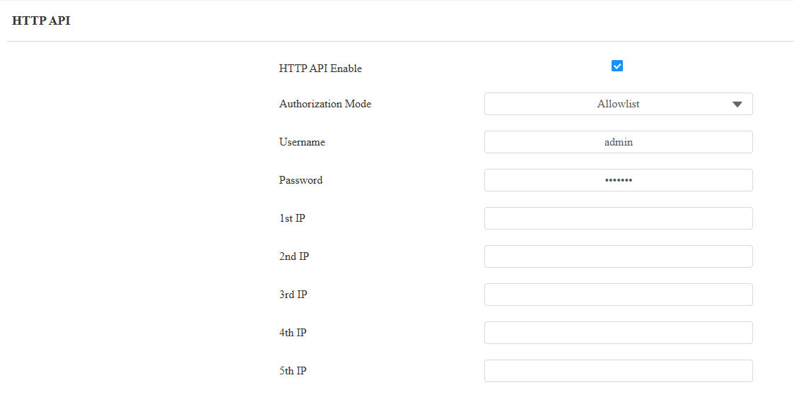
HTTP API Enable: Enable or disable the HTTP API function for third-party integration. If the function is disabled, any request to initiate the integration will be denied and return an HTTP 403 Forbidden status.
Authorization Mode: Select among the following options: None, Allowlist, Basic, Digest, and Token for authorization type, which will be explained in detail in the following chart.
Username: Enter the username when Basic or Digest authorization mode is selected. The default username is admin.
Password: Enter the password when Basic or Digest authorization mode is selected. The default password is admin.
1st IP-5th IP: Enter the IP address of the third-party devices when Allowlist authorization is selected for the integration.
Please refer to the following description for the authentication mode:
Authorization Mode | Description |
|---|---|
None | No authentication is required. This mode is intended for testing only and is not recommended in production environments. |
Allowlist | Authenticates requests based on the source IP address. Add the IP address of the third-party device to the allowlist before sending requests. Recommended for trusted LAN environments. |
Basic | Authenticates requests using a username and password. The credentials must be Base64-encoded and included in the Authorization header. |
Digest | Authenticates requests using HTTP Digest authentication. Only the MD5 algorithm is supported. |
Token | Reserved for Akuvox internal development and testing. |
Power Output Control
The device can serve as a power supply for the external relays. Click here to view the power output requirements and the wiring example.
To set it up, go to the web Access Control > Relay > 12V Relay Output interface.

12V Power Output:
Always: Provide continuous power to the third-party device.
Triggered by Open Relay: Provide power to the third-party device via 12 output and GND interface during the timeout when the status of the relays is shifted from low to high.
Integration via RS485
You can connect the device to an external device such as SR01 or an OSDP-based card reader via RS485. To make the connection effective, you need to select the right RS485 mode.
Click here to view the detailed configuration of the OSDP feature.
To make the connection effective, you need to set up the RS485 on the Device > RS485 interface.
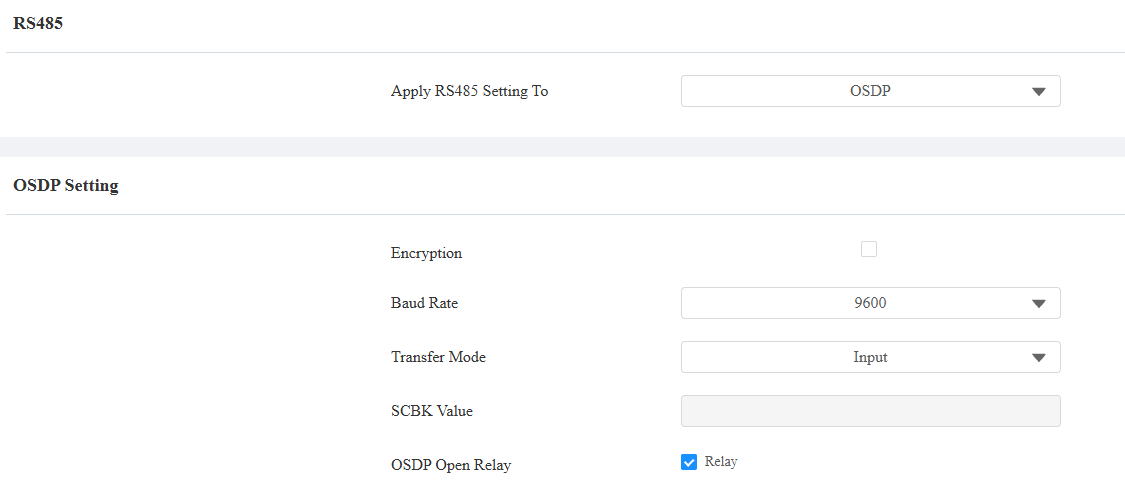
Disabled: The RS485 function is disabled.
OSDP: The device is connected to an OSDP-based external device such as a card reader.
Encryption: Check this option when the protocol is encrypted.
Baud Rate: Set the baud rate for data transmission during communication. The default is 9600, supported by Akuvox devices.
Transfer Mode: Select the RS485 working mode: Output or Input.
Local Relay Verification: When Output is selected, set whether to carry out the access credentials verification. When unchecked, door-opening failure prompts will not be given.
SCBK Value: Secure Communication Key Value.
When it is filled, OSDP will use this value for encryption, employing a customized protocol for communication.
When it is left empty, OSDP will use the default encrypted protocol for communication.
Address: The RS485 address to distinguish this device from others.
Security Relay: Select this option when the device works with the SR01.
Integration with Third-party Access Control Server
The device can transmit credential data to a third-party server without doing any verification. The generation and verification of the data are conducted on the third-party server.
To set it up, go to Access Control > Relay > Third Party Integration interface.
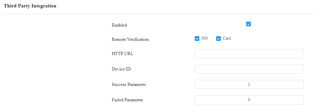
Remote Verification: Check the access method(s) to be verified by the third-party server.
HTTP URL: Enter the HTTP command in a format provided by the third-party service provider. After card swiping and PIN entry, the HTTP command will carry the dynamic information automatically before it is sent to the server for verification. See the example: http://{Server IP}:8090/api/visitor/scan?codeKey={Card}/{Pin}&deviceId={DeviceID}. For example, if a user swipes the RF card, the URL will be http://192.168.35.123:8090/api/visitor/scan?codeKey=45678999/{Pin}&deviceId=1.
Device ID: The device ID is provided by the third-party server. It will be added to the HTTP command automatically when using the credentials for door access.
Success Parameter: Receiving this value indicates that opening the door succeeds.
Failed Parameter: Receiving this value indicates that opening the door fails.
Data Transmission Type for Third-party Camera
You can select the data transmission type between the device and a third-party camera when it is connected to the SmartPlus Cloud.
To set it up, go to the Surveillance > Camera interface.

UDP: An unreliable but very efficient transport layer protocol.
TCP: A less efficient but reliable transport layer protocol. It is the default transport protocol.