Before Getting Started
The multifunctional gateway can only be added to a family through a home center device.
Ensure that both the multifunctional gateway and the home center device are upgraded to the required firmware versions before configuration. The home center must be one of the supported models listed below.
Supported Device | Required Firmware |
HyPanel (PS51) | 51.1.39.426 or later |
HyPanel V2 (PS51(V2)) | 251.1.39.406 or later |
HyPanel Plus (PS52) | 52.1.39.413 or later |
HyPanel KeyPlus (KS53) | 53.1.39.410 or later |
HyPanel Pro (PG71) | 71.1.39.423 or later |
HyPanel Ultra (PH81) | 281.1.39.415 or later |
HyPanel Supreme (PHX1) | 1001.1.39.412 or later |
HyPanel Elite 7 (PG42) | 42.1.38.93 or later |
SmartPanel (X933H) | 933.1.39.405 or later |
SmartPanel Elite 10 (C319H) | 119.1.39.405 or later |
NOTE:
The configuration path may vary depending on the panel model and firmware version. Refer to the actual interface displayed on your device.
Ensure your computer, HyPanel device, and the multifunctional gateway are connected to the same local network.
Wiring
NOTE:
Always turn off the circuit power before wiring!
The gateway can be powered by any of the following methods:
IEEE802.3af PoE
12~24VDC
100~240VAC, 50/60Hz
For detailed wiring and installation instructions, see here.
Operation Elements
LED / Button | Status | Description |
PWR/NET | Solid green | Power on; network normal |
Flashing red | Power on; network abnormal | |
Flashing green | Pairing mode active | |
LED 1-10 | Solid green/off | Relay active/inactive |
Off, no response when press the corresponding key | Relay fault | |
KEY 1-10 | / | Press to turn relay on/off |
RESET | / | Press once to reboot the gateway |
/ | Hold for more than 10 seconds to restore factor settings |
Add the Gateway to akubela System
You can add the multifunctional gateway to the akubela system through an akubela home center device or the home center’s device web portal.
Via akubela Panel
Ensure the PWR/NET LED is flashing green, indicating the gateway is in pairing mode. If not, check the network and power connections.
Choose the method based on your panel type:
On the Home screen, tap Locations at the top.
Select the room where you want to add the gateway.
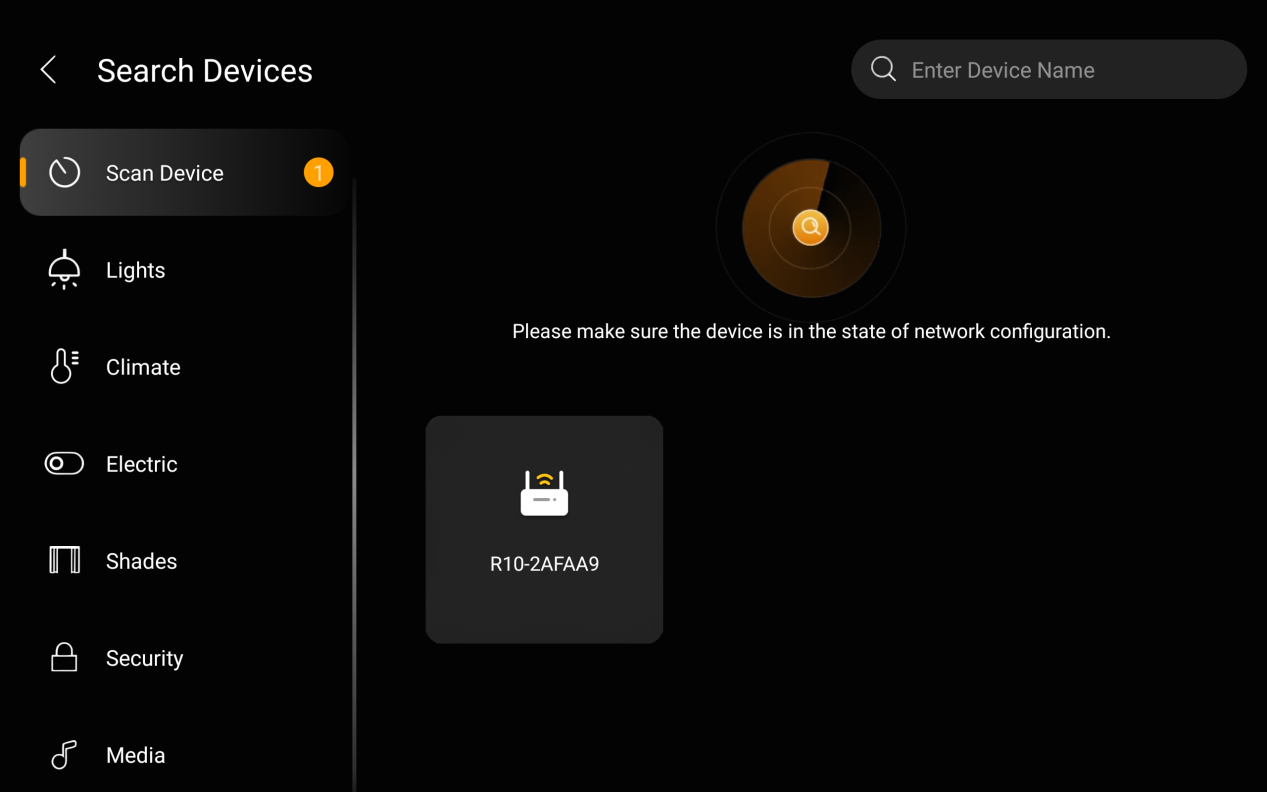
Tap +, and wait for the gateway to be detected.
Select the detected gateway (identified by the last six digits of its MAC address).
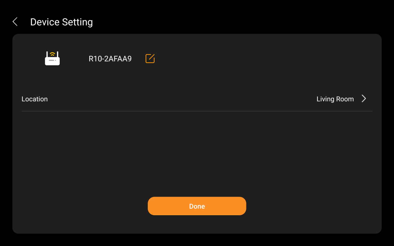
Name the gateway and assign its location, then tap Done.
Swipe down from the top edge of any screen.
Tap
 > Device Management >
  .
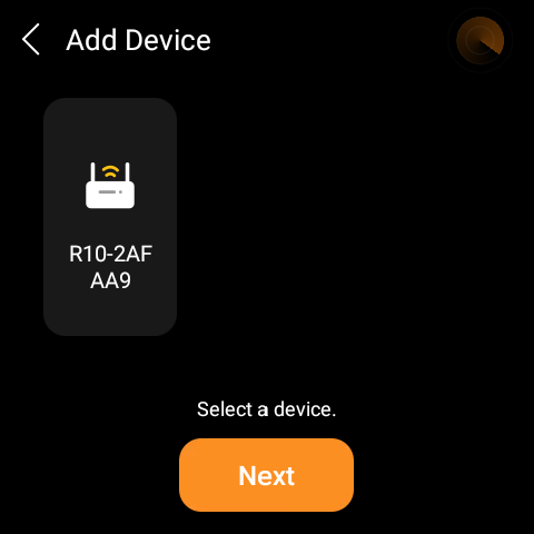
.Select the detected gateway and tap Next.
Name the gateway and assign its location, then tap Done.
Via Device Web Portal
Enter the home center’s IP address in a browser to open its device web portal.
TIP:
See here for detailed instructions.
Go to Devices >
 > Add Device > Gateway Scan to add, and select the home center device.
Wait for the gateway to be detected.
Click the detected gateway, then name it and assign its location.
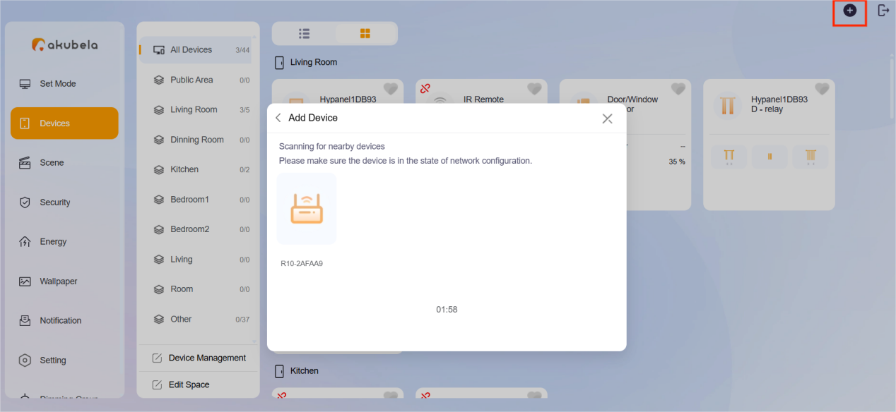
Once added, the gateway will appear in the akubela system, and its PWR/NET LED will turn solid green.
Access the Gateway Web Portal
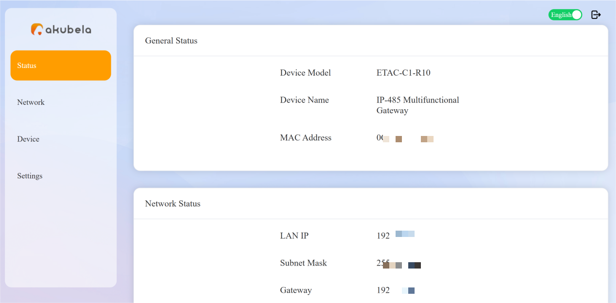
You can go to the gateway’s web portal to view basic and network information, manage connected devices, and perform operations such as factory reset, reboot, or firmware upgrade.
From the Home Center Device Web Portal
Enter the home center’s IP address in a browser to open its device web portal.
TIP:
The default login credentials are admin/admin.
Click the Setting button at the bottom of the gateway card.
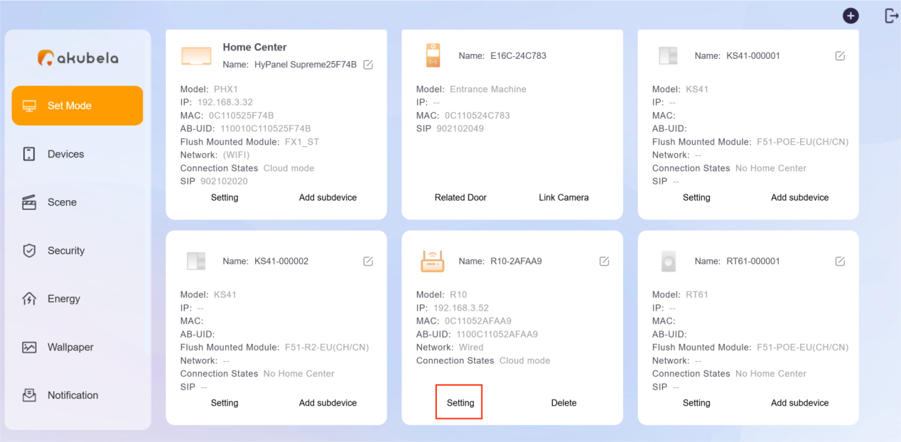
The gateway’s web portal will open in a new tab.
Directly via Gateway’s IP Address
Obtain the gateway’s IP address.
If the gateway has been added to a family: On the home center device, go to More > [R10 gateway card] >
 > IP address.
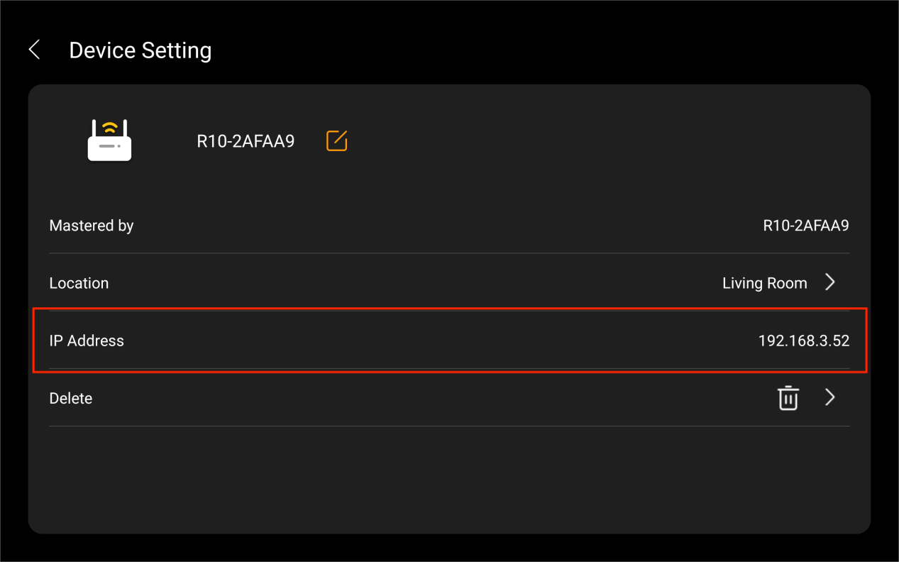
If not added: Check its IP address on the router’s management page.
Enter the gateway’s IP address in a browser.
Log in using one of the following:
If the gateway has been added to a family: Use the same credentials as the home center.
If not added: The default username and password are admin/admin.

Configure Devices
NOTE:
Any relays, inputs, or RS485 devices configured before the gateway is added to a family will be retained automatically, so you don’t need to reconfigure them.
Removing the gateway from the family will restore all its configurations to factory settings.
Configure Relays
Log in to the gateway’s device web portal.
Go to Device > Relays.
Enable the desired relay and configure its settings.
NOTE:
The configuration options vary by relay type.
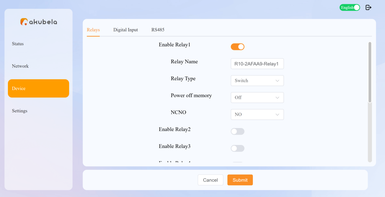
Setting | Description |
Relay Name | Assign a name to identify the relay. |
Relay Type | Select the type. |
Power Off Memory | Choose whether the relay retains its state after a power outage. |
NCNO | Select the contact type based on wiring:
|
Combination (Available when the relay type is Shade-open, Shade-close, Heating, or Cooling) |
|
Upper Hysteresis Value (Available when the relay type is Heating or Cooling) | Set the upper temperature difference for hysteresis control. |
Lower Hysteresis Value (Available when the relay type is Heating or Cooling) | Set the lower temperature difference for hysteresis control. |
Temperature Source (Available when the relay type is Heating or Cooling) | Select the temperature sensor to use for control. |
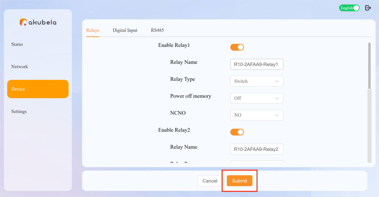
Click Submit to save the settings.
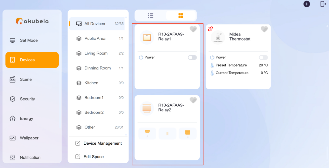
Once added, the relays will appear in the family system.
Configure Digital Inputs
Go to Device > Digital Inputs.
Enable the desired input and configure as follows:
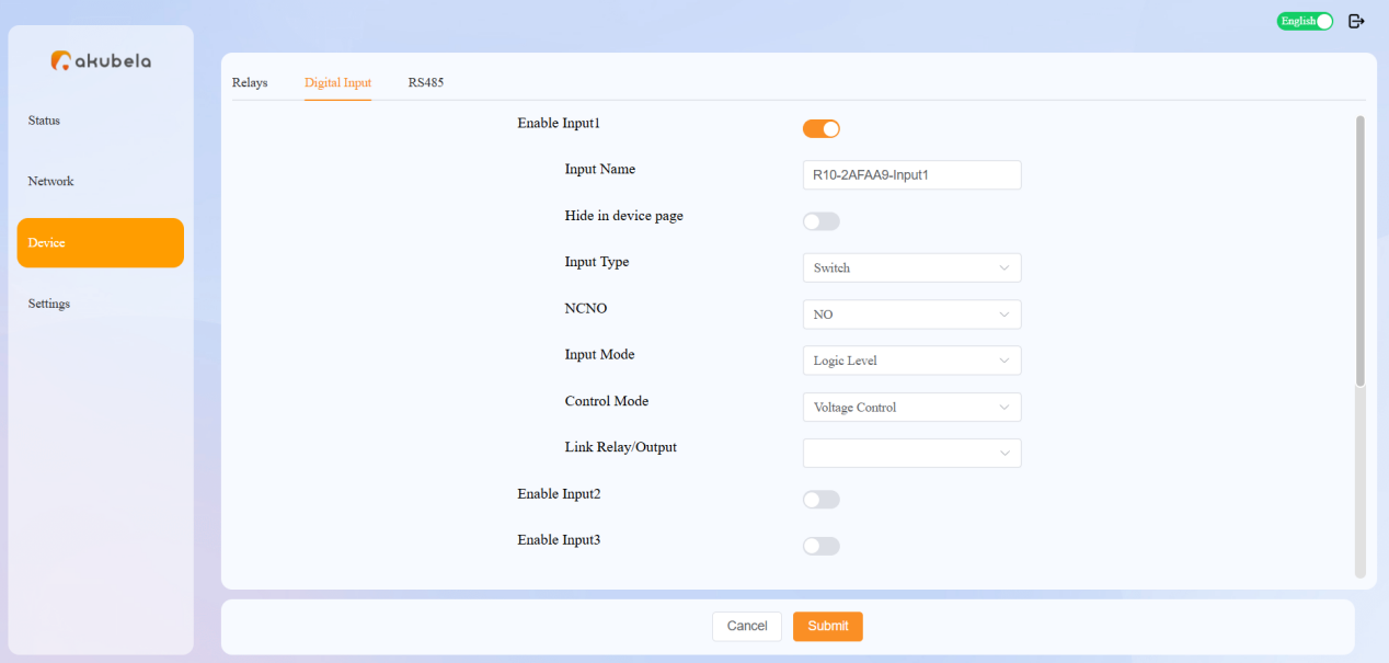
Setting | Description | Remark |
Input Name | Assign a name to identify the input. | |
Hide in Device Page | Choose whether to hide this input on the akubela system. | Enabled by default for Shade types. |
Input Type | Select the type. | |
NCNO | Select the contact type based on wiring:
| |
Input Mode (Available when the input type is Shade-open, Shade-close, or Switch) | Choose:
| |
Control Mode (Available when the input mode is Logic Level) | Choose:
| |
Click Duration (Available when the input mode is Pulse) | Set the duration of a short click. | |
Long Click Duration (Available when the input mode is Pulse) | Set the duration of a long click. | |
Link Relay/Output | Link this input to trigger a specific relay or output (shade type excluded) on the same gateway. | |
Combination Input (Available when the relay type is Shade-open or Shade-close) | Link another shade input to form a complete open/close pair. |
Click Submit to save the settings.
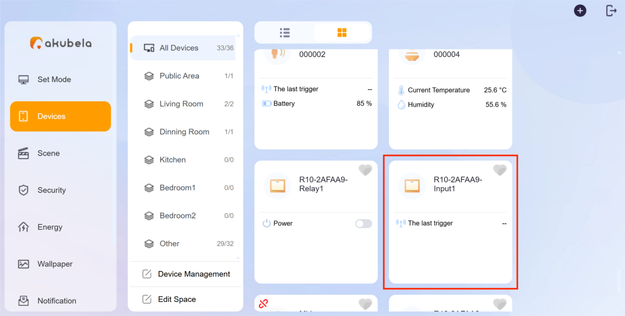
Once added, inputs that are not set to hidden will appear in the family system.
Configure RS485 Devices
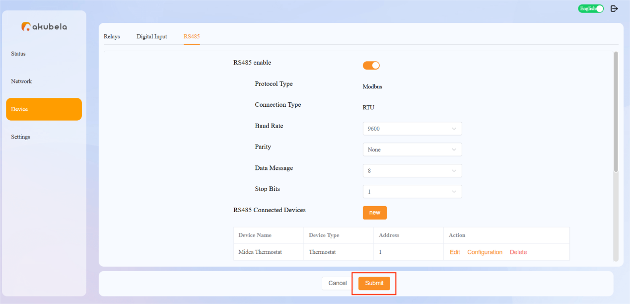
Log in to the gateway’s device web portal, and go to Device > RS485.
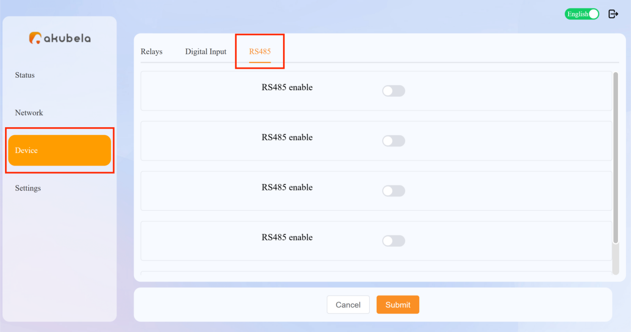
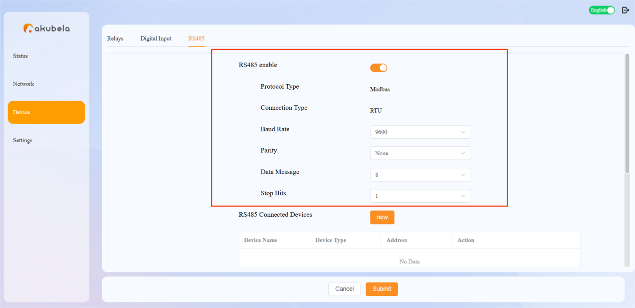
Toggle the specific RS485 enable button to On.
Configure the parameters (Optional. Typically do not need to be changed) :
Baud Rate: Set the data transmission speed. Default: 9600.
Parity: Choose the error checking method. Default: None.
Data Message: Default: 8.
Stop Bits: Default: 1.
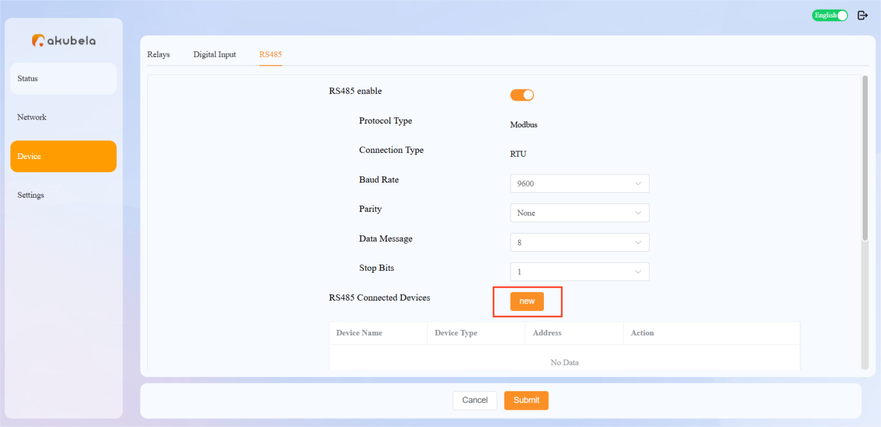
Click New to add an RS485 device.
NOTE:
Currently supports Midea thermostats only.
Enter the device name and device address.
NOTE:
The entered address must match the address set on the device.
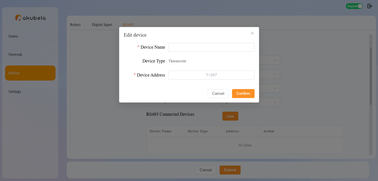
Click Confirm, and the device will appear in the list.
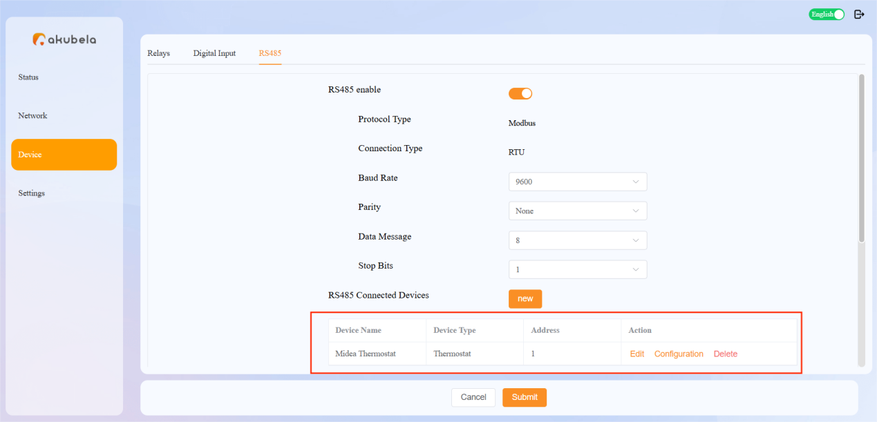
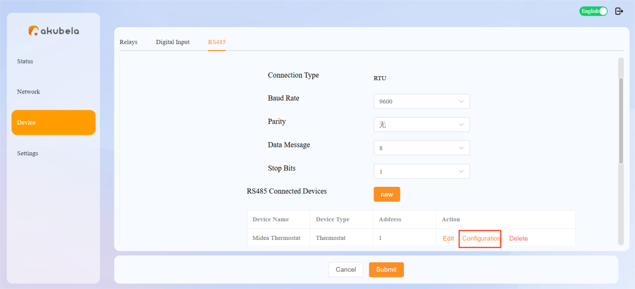
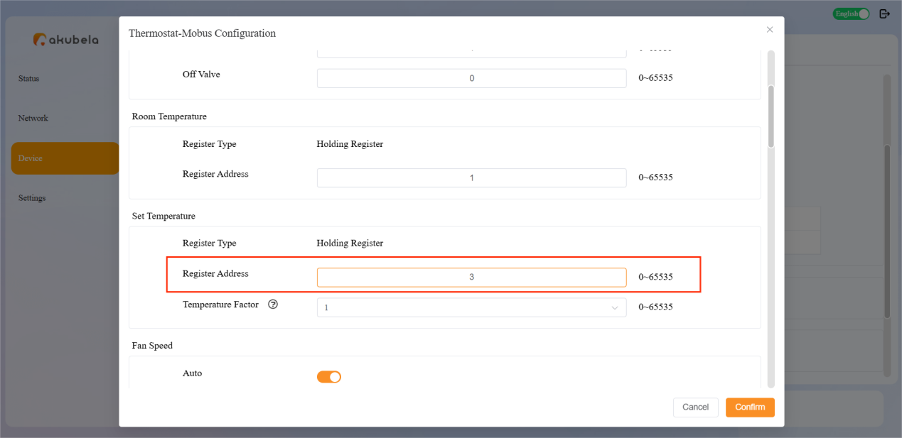
Click Configuration to open the device settings.
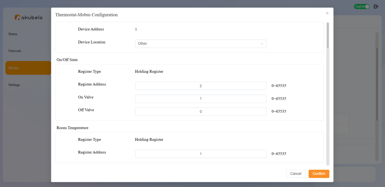
NOTE:
When configuring a Midea thermostat, set the Register Address under Set Temperature to 3 and click Confirm. No other parameter changes are required.
Click Submit to save.
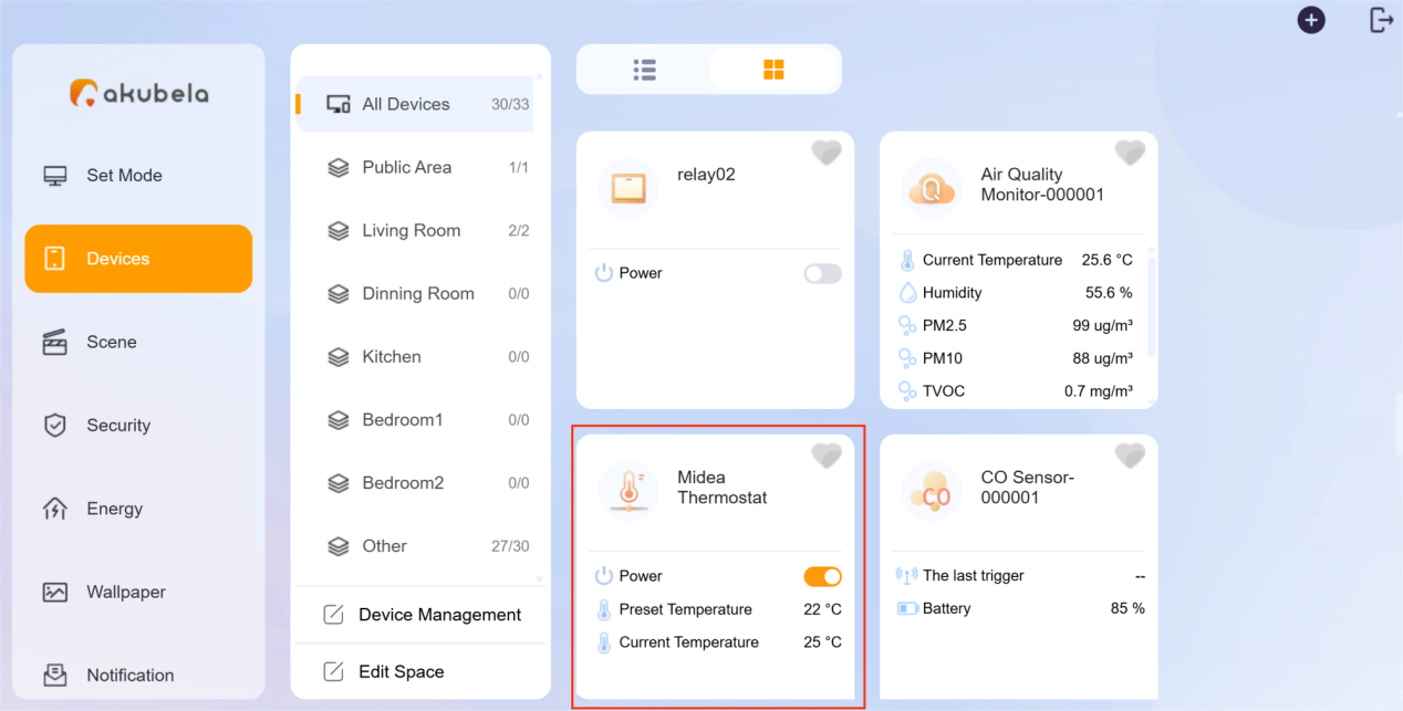
Once added, the device will appear in the family system.
Maintenance
Restart the Gateway
To restart the gateway, use either of the following methods:
Press the physical RESET button once to reboot the gateway.
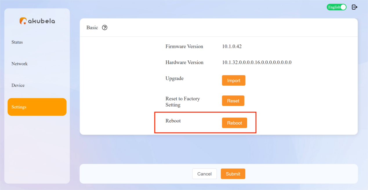
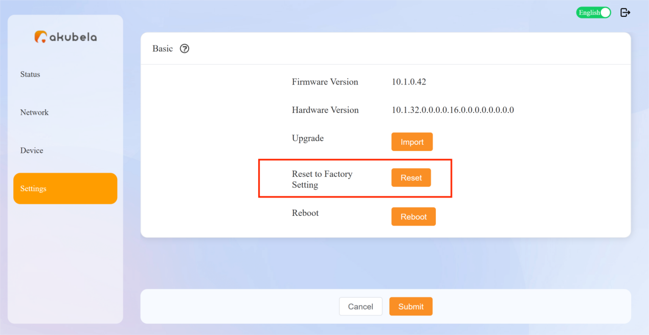
On the gateway’s device web portal, go to Settings > Reboot.
Restore Factory Settings
To reset the gateway to factory settings, use either of the following methods:
Press the physical RESET button for about 10 seconds.
On the gateway’s device web portal, go to Settings > Reset.
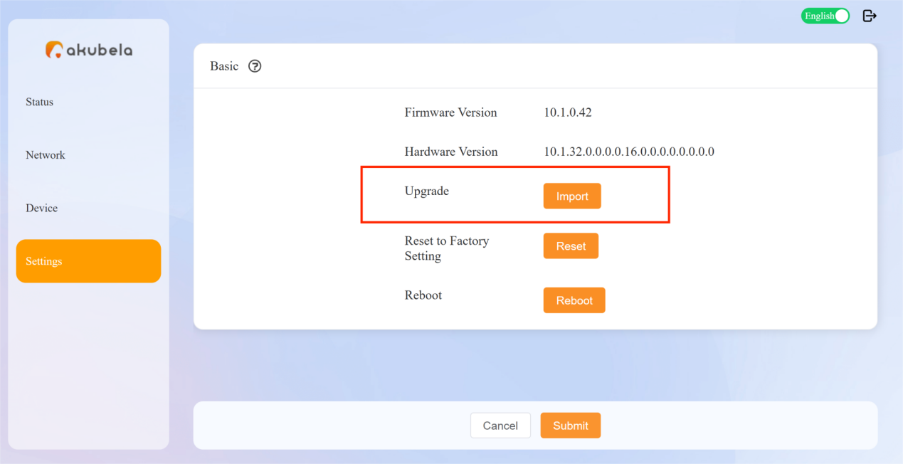
Upgrade Firmware
Contact akubela technical support to obtain the latest firmware file.
Log in to the gateway’s device web portal.
Go to Settings > Import, then upload the firmware file.