
1. Overview
The Device Configuration App(hereinafter DCA) is an ETS plugin for configuring DALI gateways. Embedded within the DALI gateway application, it streamlines addressing, commissioning, configuration, upgrades, and monitoring of failure information on the DALI bus.
This manual provides an overview of the DCA’s framework, functions, and operational procedures.
1.1. Functions
DCA is able to assign and modify the address of the DALI driver, and map the ECG in the ETS to the DALI driver. It can also configure driver control and parameter, group, sensor, scene, etc., to the DALI driver.
The DCA allows users to assign and modify DALI driver addresses and map the ECGs in ETS to the corresponding DALI drivers. It also supports driver control, parameter configuration, group assignments, sensor setup, and scene management for DALI drivers.
DCA Key Functions:
Import/Export configuration
Initialize the DALI bus & assign address to DALI driver
Query driver status on the DALI bus & read DALI driver configurations
Adjust driver addresses with programmed addresses & modify the association of the ECG with the driver address
Read or modify driver parameters
Control DALI drivers on both channels via unicast, multicast, or broadcast, supporting switching, dimming, color temperature, and color adjustments
Assign drivers to groups and specify associated groups
Configure DALI scenes, assigning scenes to drivers and setting scene brightness, color temperature, and color
Edit and test global scenes
Integrate sensors, associating up to 8 KNX sensor channels and modifying sensor addresses
Upgrade the DALI software on the gateway
1.2. DCA Download and Installation
The DCA .etsapp file can be obtained from the manufacturer or the myKNX account store.
1.2.1. Download DCA
(1) Log in to https://my.knx.org/.
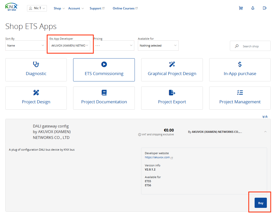
(2) Go to Shop > ETS Apps, select the app developer as “AKUVOX”, and scroll down to click Buy.
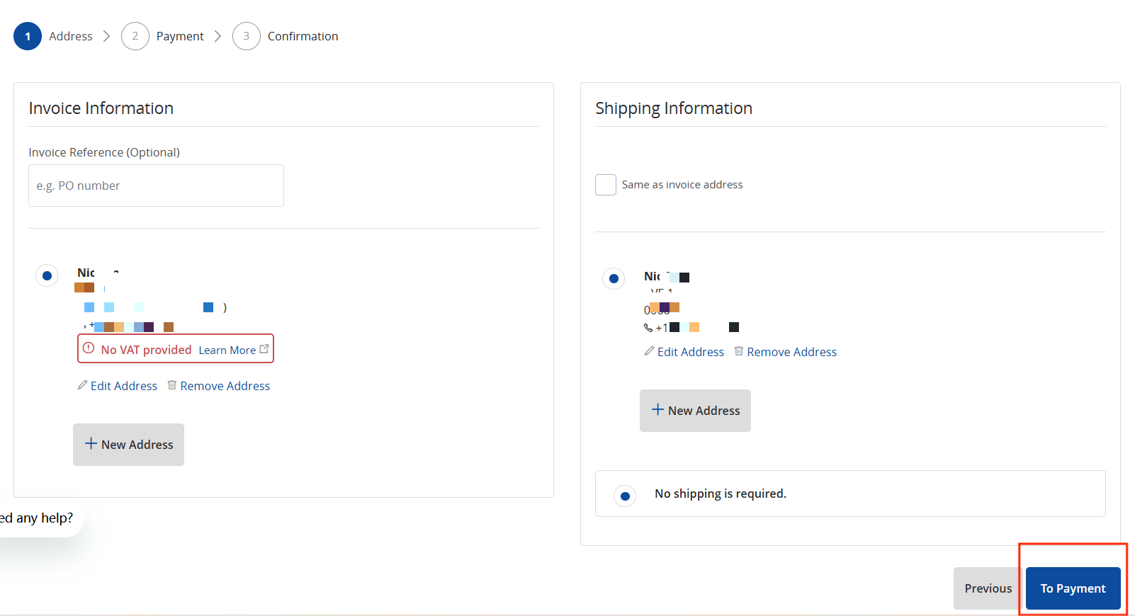
(3) Click ![]() at the top right, click Checkout, add the invoice and shipping information, then click To Payment.
at the top right, click Checkout, add the invoice and shipping information, then click To Payment.
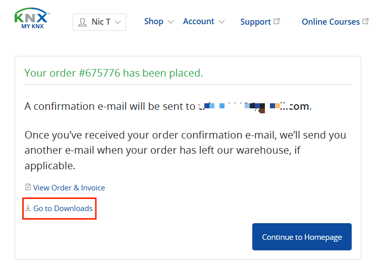
(4) Click To Confirmation > Confirm Order > Go to downloads.
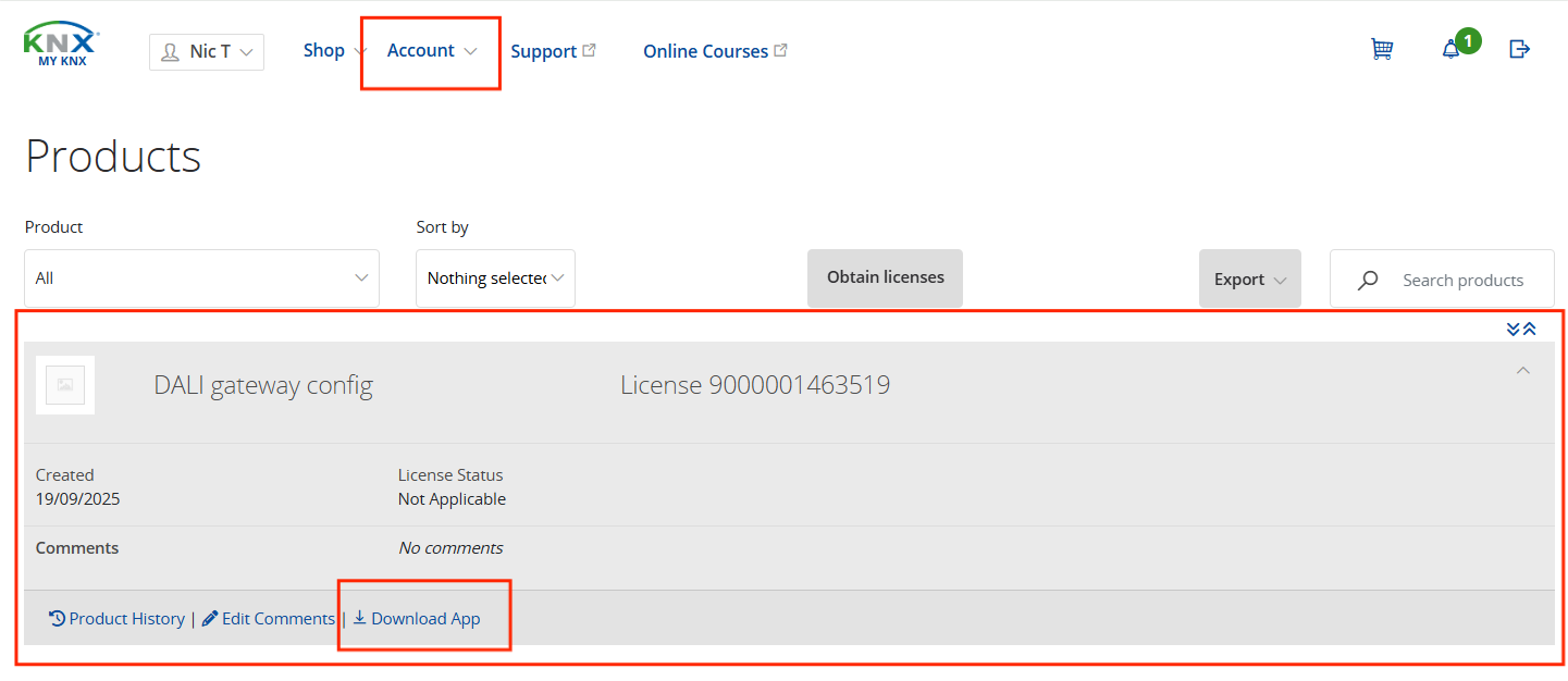
(5) Go to Account > Products, click on the DALI gateway config, and click Download App.
1.2.2. Install DCA
NOTE:
This feature requires a licensed ETS version with an ETS dongle installed. Supported versions include ETS5 Lite, ETS5 Supplementary, ETS5 Professional, ETS6 Lite, ETS6 Professional, or higher.
If an older version of the app is installed, delete it first, then restart ETS5 before adding the new version.
In ETS5
Open ETS5 and click Add App in the lower-right corner.
In ETS6
Open ETS6 and go to Settings > ETS Apps > Install App from file.
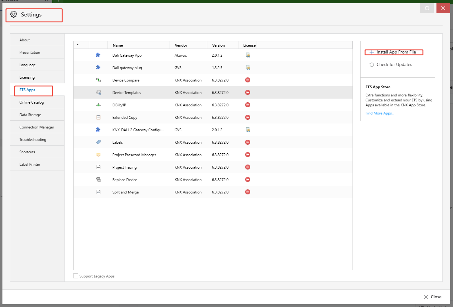
Once installed, the DCA menu will appear in the database editing interface of your DALI gateway project. Click it to open the DCA configuration interface.
1.3. Operation Steps
This chapter describes the operation flow and precautions for commissioning the DALI bus using DCA. The following steps apply to newly installed or updated projects:
(1) Ensure ETS is a licensed version with the ETS dongle installed and that the DCA .etsapp file is correctly installed.
(2) Short-press the Test/Set button to trigger broadcast switch control and verify that all DALI devices are properly connected.
(3) Set device parameters in ETS and download them to the gateway..
NOTE:
ECG devices in ETS are by default matched to driver addresses on the DALI bus. Associations can be modified via DCA.
DCA uses point-to-point communication and shares a bus interface with device commissioning. When downloading databases or diagnosing devices, disconnect DCA first to avoid errors such as “Download(Appl.) failure” or “Device exists, but failed to connect” (see Fig. 1.3(1) and Fig. 1.3(2)).
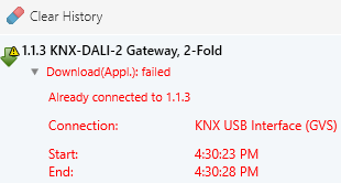
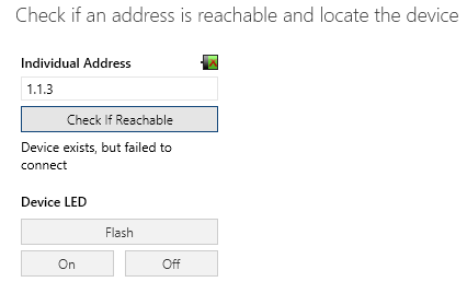
Fig.1.3(1) Download(Appl.) failure Fig.1.3(2)Device exists,but failed to connect
(4) Open the DCA editing interface, select the commission channel and read the device status.
(5) In initialization, click “[All] init DALI device” or “[No Addr] init DALI device” to assign unique addresses to all drivers on the DALI bus.
(6) Sync DALI bus and obtain the DALI driver list: Use DCA to read the status of all drivers.
(7) Obtain the ECG list: Click “Synchronize ETS data” to obtain the list of ECGs configured in ETS.
NOTE:
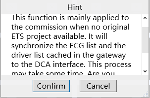
If no database source file is available, click “Sync. Gateway” to read the ECG and DALI driver lists cached by the gateway.
(8) Modify ECG-to-driver association and download it to the gateway.
Methods:
Drag the grid to associate the ECG to the specified driver address.
Right-click a device in the grid and select “Modify Address”.
NOTE:
The ECG type must be the same as the driver type at the corresponding address; otherwise, DCA will report an error.
(9) Configure driver parameters: Double-click a device in the grid to open the driver detail page and modify parameters such as device settings and scene configuration.
NOTE:
Changes take effect only after being loaded on the configuration page.
(10) Click “Sync. Gateway” to read the data in the gateway and verify that all information is correct.
NOTE:
If the above steps are not followed, DALI devices may not operate according to preset brightness values.
During address assignment, if some addresses are incomplete, start initialization without address assignment in DCA.
If allocation fails more than twice, perform a full DALI bus initialization using DCA or by long-pressing the Test/Set button on the DALI gateway for more than 5 seconds. This may change assigned addresses. Afterward, verify that ECG types match actual driver types to ensure full functionality.
(11) Export configuration, and save the gateway configuration after completing all settings.
2. DCA Interface
2.1. Main Interface
Open the device database, then click DCA in the database edit menu to access the DCA main interface (initial interface) as shown in Fig. 2.1.
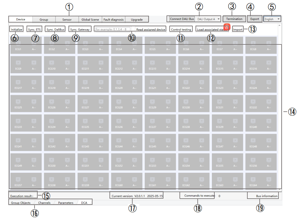
Fig.2.1 DCA main interface
① Switch Configuration Interface: Switch between interfaces for Device, Group, Sensor, Global Scene, Fault Diagnosis, and Upgrade. See Sections 2.2–2.7 for details.
② Connect DALI Bus: Select a channel and connect to the gateway.
NOTE:
The gateway must have a physical address assigned before it can connect.
When reconnecting the gateway, ETS data is automatically synchronized (e.g., switching from disconnected to connected state or switching between A/B channels).
③ Terminate Operation: Click Termination to stop operations on the DALI gateway. For example, terminating while reading driver status will end the DCA configuration or reading process. Terminating during bus initialization may cause the initialization to fail.
NOTE:
If the DALI bus is busy or has a large amount of data, you may terminate the operation. Commands already executed or data already sent are unaffected; only unexecuted telegrams will stop.
④ Export: After configuring a DALI gateway, export and save the configuration.
NOTE:
The configuration of A/B channel needs to be exported separately. The export file includes: Device Configuration, Scene Configuratin and Sensor Configuration.
⑤ Language Switch: Click to toggle the interface language between Chinese and English.
⑥ Initialization: Click to select “[All] init DALI device” or “[No Addr] init DALI device”.
[All] init DALI device: Initialize all drivers. Assign DALI addresses to all DALI driver on the current channel. Suitable for first-time setup.
NOTE:
This operation randomly reassigns driver addresses, which may disrupt ECG-to-driver associations. Use with caution.
[No Addr] init DALI device: Initialize only drivers without addresses, leaving existing addresses unchanged. Suitable for new or replacement drivers.
NOTE:
If address assignment is incomplete, use “[No Addr] init DALI device”. If it fails more than twice, use “[All] init DALI device”.
⑦ Sync ETS Data: Synchronize ETS device configurations to DCA.
⑧ Sync DALI Bus: Click to read the driver list directly from the DALI bus.
NOTE:
If there is a driver address conflict on the DALI bus, the DCA will report an error. You can flash the conflicting driver or delete its address. It is recommended to reinitialize the bus to reassign addresses.
⑨ Sync Gateway: Read the saved data on the gateway, including ETS and DCA configuration information. If any information is missing, the data will appear empty. Clicking this option will display the following prompt.
NOTE:
Before performing the “Sync Gateway” operation, ensure that Download Database and Download DCA Configuration have been completed. If the gateway has not received a configuration previously downloaded by DCA, it will report the default configuration, which may not reflect the actual setup.
⑩ Read Assigned Device: In the driver list, select one or more DALI driver addresses and click "Read Assigned Device" to retrieve the driver information from the gateway cache and display it in the software in real time.
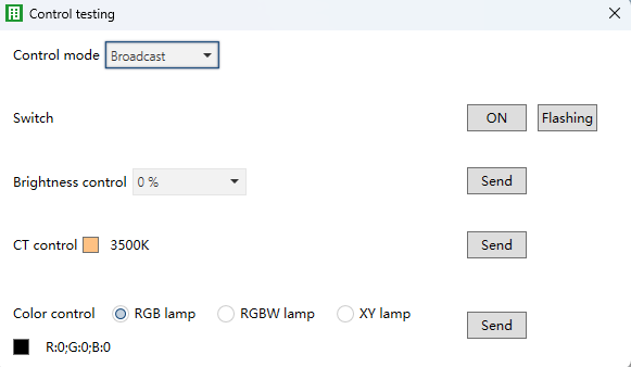
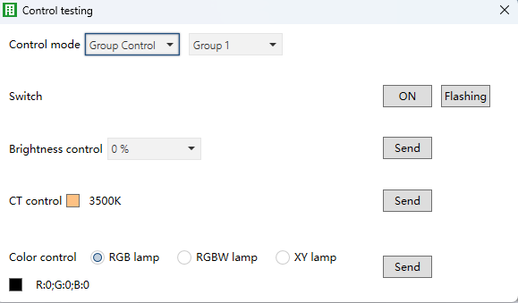
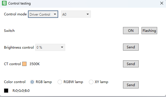
⑪ Control Testing: Click to send DALI control commands to the current channel’s bus, including switch, brightness, color temperature, and color adjustments, to test the connected drivers. Control can be performed in broadcast, group, or individual modes.
Broadcast: Send the same command to all DALI drivers.
Group Control: Group multiple DALI drivers together and control all the drivers in the same group simultaneously through group address (Group 1~Group 16).
Driver control: Controls a specific driver by address (A0–A63).
⑫ Load Associated Status: Click to send the ECG, driver address and its associations to the gateway.
NOTE:
If the DCA has not previously read or configured the driver parameters, they will not be sent by default. After loading, re-read via Sync Gateway if needed.
⑬ Import: Import a DALI gateway configuration. Imported driver data will be displayed on this page and can be modified and applied.
NOTE:
The imported file must be named “DeviceConfiguration.json”; other names or formats cannot be imported.
⑭ Display all DALI drivers. For details, see section 2.2.1-2.2.2.
⑮ Execution Results: Display results of DCA operations.
⑯ Database Edit Menu: Show the edit menu for DALI devices..
⑰ Current Version: Display the current DCA version.
⑱ Commands to Execute: Display the command waiting to be executed on the DALI bus.
⑲ Bus Information: Display bus voltage and current (if available).
2.2. Device
After synchronizing the DALI bus, this page displays the association between ECGs and driver addresses, as shown in Figure 2.2. The available operations are as follows:
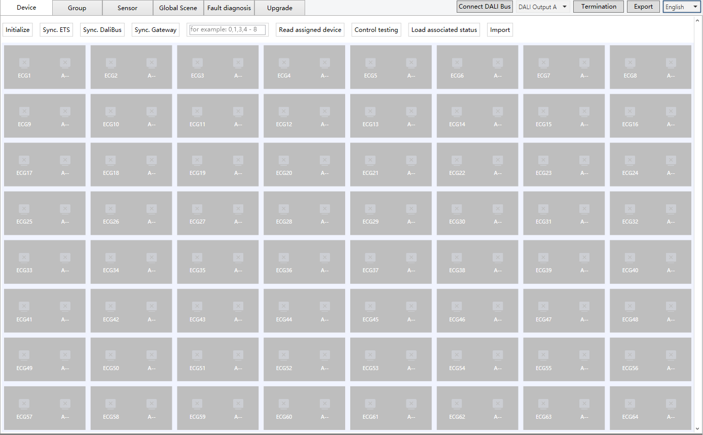
Fig.2.2(1) Group/ECG
(1) The grid displays the mapping between ECG configuration and driver address.
① Displays the ECG number (1–64) and its corresponding ECG type icon in ETS. (Different ECG types have different icons.)
② Displays the actual driver address (A0–A63) and its corresponding driver type icon. (Different driver types have different icons.)
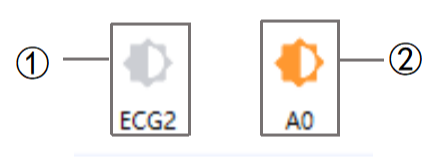
Fig.2.2(2)
(2) To change the mapping, press and hold a device grid, drag it onto another device grid, and release it. The DCA tool will automatically check the relationship and display any error prompts if needed.
NOTE:
Dragging a device grid reassigns the ECG configuration to another driver address. The driver number defaults to 1–64, with only the associated ECG number being modified.
Device Grid Status Indicators
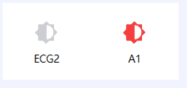
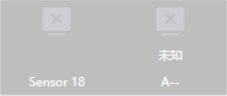
Normal: When the light is on, the icon is highlighted (see Fig. 2.2(4)); when the light is off, the icon is grayed out (see Fig. 2.2(5)).
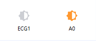
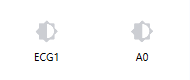
Fig.2.2(4)Turn on the light Fig.2.2(5)Turn off the light
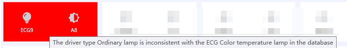
Error - Type mismatch: If the driver type does not match the ECG type in the database, an error will appear when hovering over the device grid(see figure below). In this case, adjust the association between the ECG and the driver address.
NOTE:
The ECG type set in ETS must match the actual driver type, otherwise certain functions cannot be controlled. For example, if driver address A8 is a Color Temperature lamp, ECG9 must also be configured as a Color Temperature type. If mismatched, hovering over the card will show the error above.
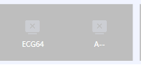
Error - Driver not linked to an ECG:
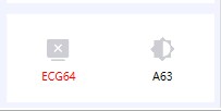
Error - ECG not linked to a driver:
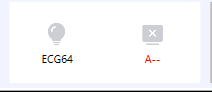
Error - No driver configured for this address: The ECG is not associated with this address, and no driver is configured at the corresponding address.
Error - Drive failure:
(3) Right-click on a device grid to send control commands (switch on/off, brightness, color temperature, color—depending on driver type), or to modify or delete an address. See sections 2.2.1.1–2.2.1.8 for details.
(4) Double-left-click on a device grid to open the driver details page. Here you can view the driver address and type, configure scenes, set device attributes, and send control commands. See section 2.2.2 for details.
NOTE:
You can only access the driver details page if the corresponding DALI driver card has been read.
If an ECG is not associated with a driver, you can still open the details page via its DALI address and directly control the driver.
2.2.1. Device Grid
By right-clicking on a device grid, you can control attributes such as switch, brightness, color temperature, color, modify address, or delete address. Available options depend on the driver type. For example, if a driver does not support color, the color option will not appear.
2.2.1.1. Switch
Right-click the device grid to switch the light on/off. The icon updates to reflect the light’s status, as shown in Fig. 2.2.1.1(1) and Fig. 2.2.1.1(2).
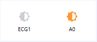
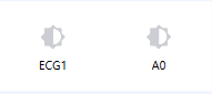
Fig.2.2.1.1(1)Turn on the light Fig.2.2.1.1(2)Turn off the light
Right-click the device grid to adjust brightness, as shown in Fig. 2.2.1.2(1). Hovering over the grid displays the current brightness value, as in Fig. 2.2.1.2(2).
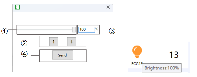
Fig.2.2.1.2(1) Adjust the brightness Fig.2.2.1.2(2) Brightness
① Adjust the brightness percentage using the slider.
② Click on the icon to increase/decrease brightness.
③ View or manually enter the brightness value.
④ Click to send the current brightness value to the DALI bus.
2.2.1.3. Color temperature
Right-click the device grid to adjust color temperature, as shown in Fig. 2.2.1.3(1). Hovering over the grid displays the current value, as shown in Fig. 2.2.1.3(2).
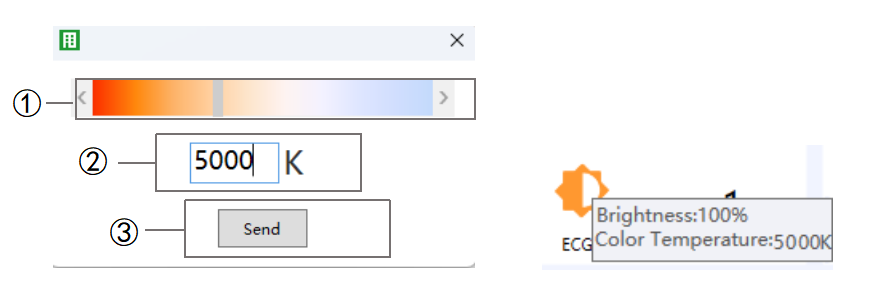
Fig.2.2.1.3(1) Adjust the color temperature Fig.2.2.1.3(2) color temperature value
① Use the slider or click on the icon “ ” “
” “ ” to adjust the color temperature.
② View or manually enter the color temperature value.
③ Click to send the current temperature value to the DALI bus.
2.2.1.4. RGB
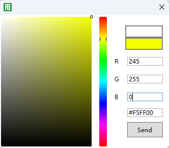
Right-click the device grid to adjust RGB values, as shown in Fig. 2.2.1.4(1). Hovering over the grid displays the current RGB value, as shown in Fig. 2.2.1.4(2).
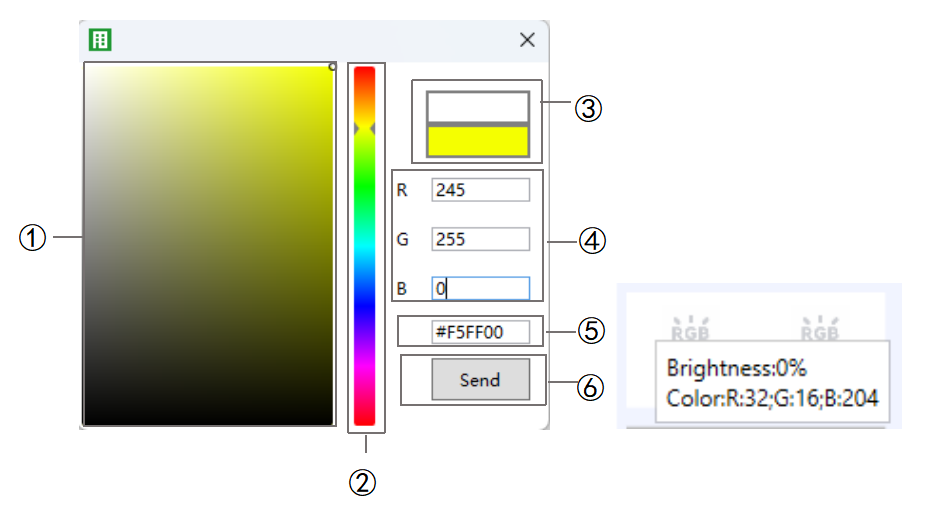
Fig.2.2.1.4(1) Adjust the RGB Fig.2.2.1.4(2) RGB value
① Select a color on the palette.
② Adjust color using the slider.
③ Preview the current color effect.
④ Enter the RGB value manually.
In the DALI system, a value of 255 for R/G/B means “unchanged.” When set to 255, the system actually sends 254.
⑤ View or edit the RGB value..
⑥ Click to send the current color value to the DALI bus.
2.2.1.5. RGBW
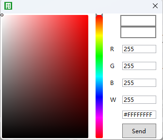
Right-click the device grid to adjust RGBW values, as shown in Fig. 2.2.1.5(1). Hovering over the grid displays the current value, as shown in Fig. 2.2.1.5(2).
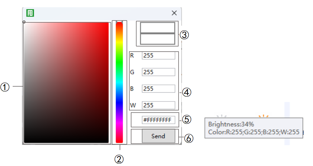
Fig.2.2.1.5(1) Adjust the RGBW Fig.2.2.1.5(2) RGBW value
① Select a color on the palette.
② Adjust color using the slider.
③ Preview the current color effect.
④ Enter the RGBW value manually.
NOTE:
In the DALI system, a value of 255 for R/G/B means “unchanged.” When set to 255, the system actually sends 254.
⑤ View or edit the RGBW value.
⑥ Click to send the current color value to the DALI bus.
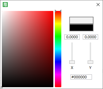
2.2.1.6. XY
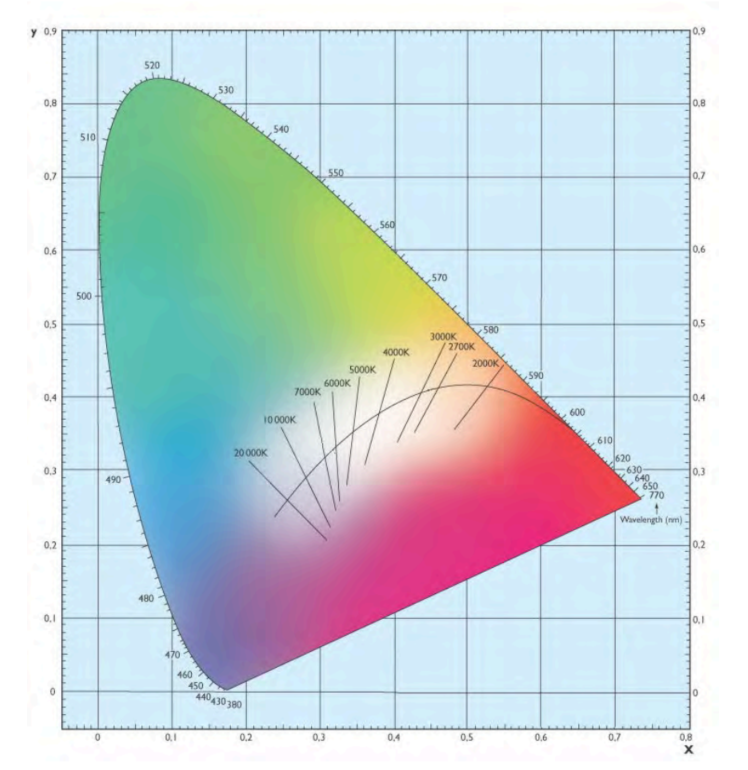
Right-click the device grid to adjust XY values, as shown in Fig. 2.2.1.6(1). Hovering over the grid displays the current XY value, as shown in Fig. 2.2.1.6(2).
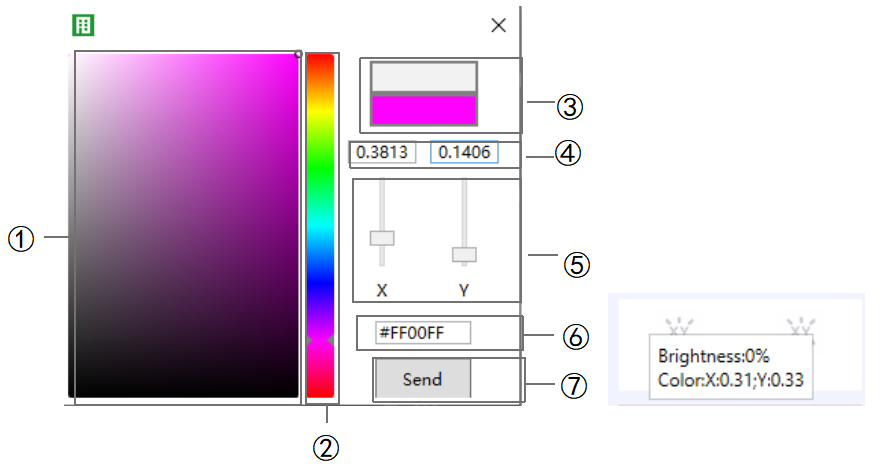
Fig.2.2.1.6(1) Adjust the XY Fig.2.2.1.6(2) XY value
① Select a color on the palette.
② Adjust color using the slider.
③ Preview the current color effect.
④ View or manually enter XY values.
⑤ Adjust XY values using the slider.
NOTE:
In the DALI system, X + Y must be less than 1 to generate a valid color.
X/Y = 1 means “unchanged.”
⑥ View the current color value (manual entry is invalid here).
⑦ Click to send the current color value to the DALI bus.
NOTE:
If the XY color value is outside the valid range (e.g., 0.01/0.01), the control value is invalid.
Right-click the device grid to modify the address, as shown in Fig. 2.2.1.7.
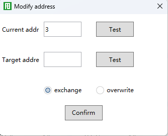
Fig.2.2.1.7 Modify address
Exchange: Swap the ECG configuration of the current address with the target address.
Overwrite: Replace the current address with the target address.
NOTE:
The target address will be deleted when using Overwrite.
Right-click the device grid to delete the address, as shown in Fig. 2.2.1.8.
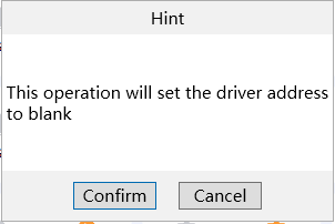
Fig.2.2.1.8 Delete address
2.2.2. Device Grid Detail Interface
Double-left-click a device grid to open its detail page. Here you can view the driver address and type, check or change configuration, set up scenes, and send control commands. Examples are shown in Fig. 2.2.2(1)–(4).
NOTE:
Data is only cached once the detail page has been opened.
Available options depend on the driver type. For example, if a driver doesn’t support color, color controls won’t be shown.
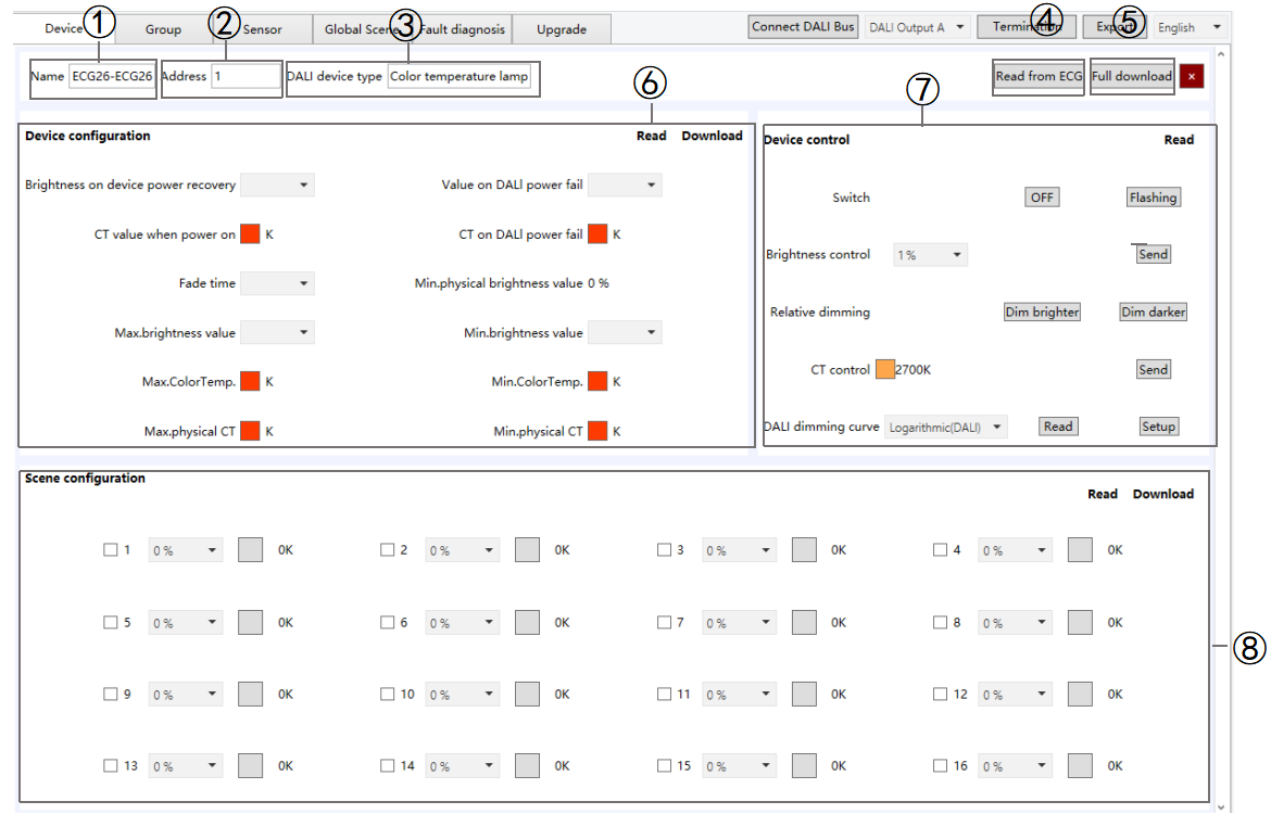
Fig.2.2.2(1) Color temperature
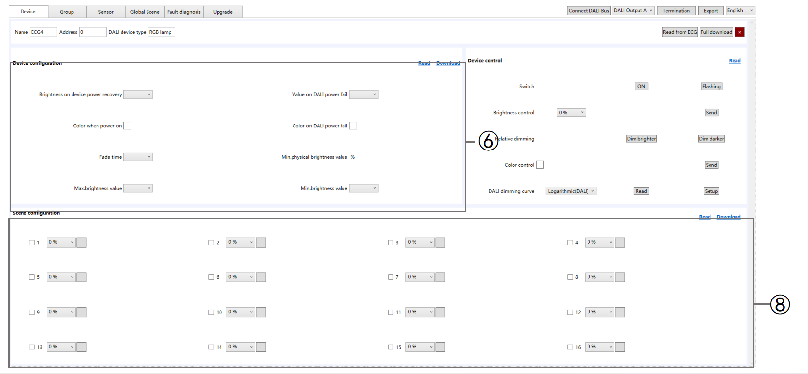
Fig.2.2.2(2) RGB
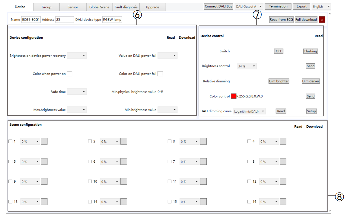
Fig.2.2.2(3) RGBW
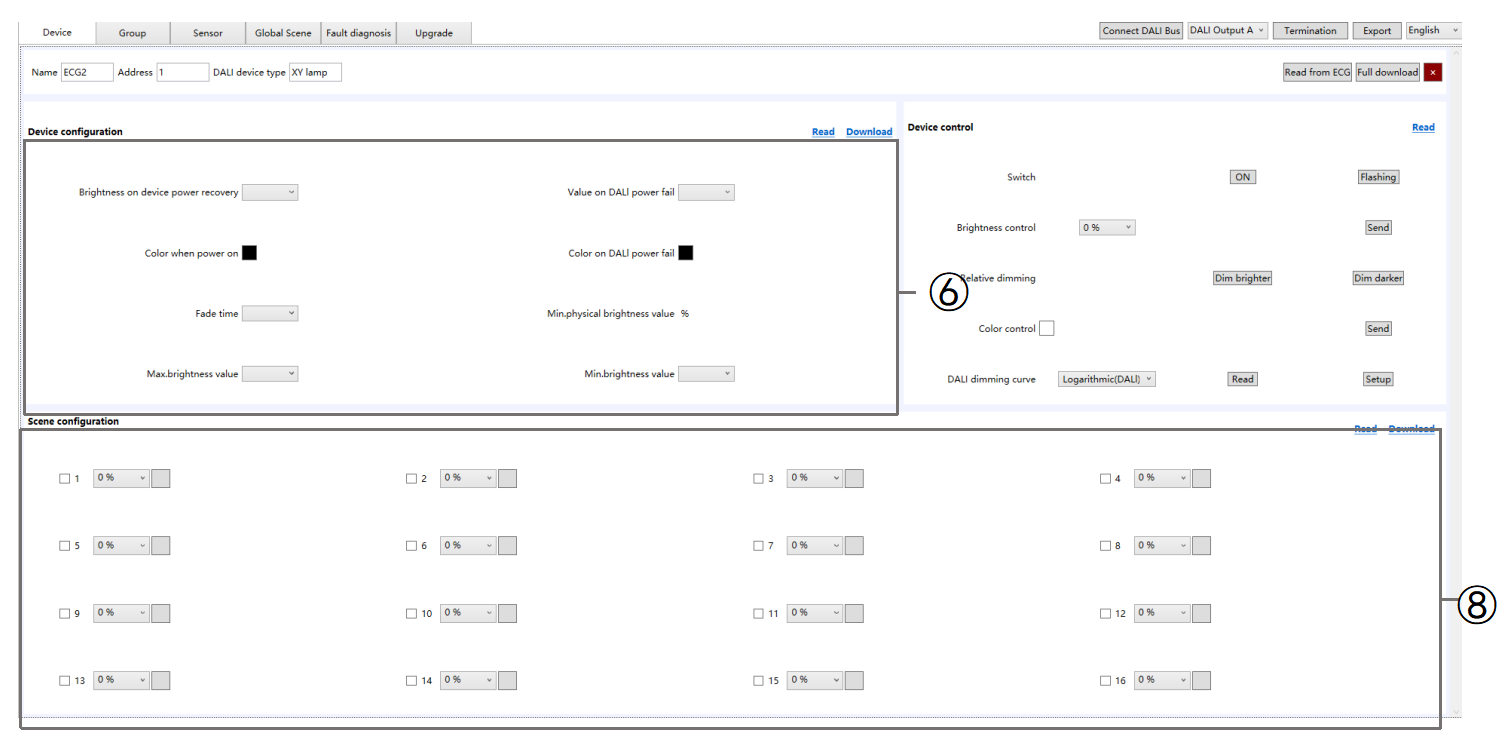
Fig.2.2.2(4) XY
① Name: Show the device name which is set in ETS.
② Address: Display the address of the selected driver.
③ DALI Device Type: Display the type of the selected driver.
④ Read from ECG: Read driver details (type, configuration, scenes) from the ECG and sync them to the DCA.
⑤ Load all Para.: all configuration and scene data to the driver.
⑥ Device Configuration (varies by driver type)
Brightness on ECG power recovery: The brightness level applied when power is restored.
Value on DALI power fail: The brightness level applied if DALI communication is lost.
CT value when power on: The color temperature applied when communication is lost and then restored (Range: 1000-10000).
CT on DALI power fail: The color temperature applied when communication is lost (Range: 1000-10000).
Color when power on: Color applied when communication is lost and then restored (recovers the same color as set for Color on DALI power fail).
X/Y Optio
n: 0-1
R/G/B/W Option: 0-255
Color on DALI power fail: Color applied if DALI communication is lost.
X/Y Option: 0-1
R/G/B/W Option:0-255
NOTE:
In the DALI system, setting X/Y to 1 or R/G/B/W to 255 means “no change.” In this case, the driver will keep and execute the previously applied color value.
Fade time: The default transition time for the driver. All adjustments for brightness, color temperature, and color are applied according to this setting.
Min. physical brightness value: The lowest physical brightness the driver can execute, representing the minimum level required to turn on the lamp. This value is read-only.
Max. brightness value: The highest brightness the driver can execute, which is the maximum level controllable by the DALI Gateway. If a higher value is received, the driver will apply its internal logic, usually setting the brightness to the maximum.
Min. brightness value: The lowest brightness the driver can execute, linked to the light’s minimum physical brightness. If a lower value is received, the driver will apply its internal logic, usually setting the brightness to the minimum.
Max. color Temp: The highest color temperature the driver can execute, representing the maximum color temperature controllable by the DALI Gateway.
Min. color Temp: The lowest color temperature the driver can execute, representing the minimum color temperature controllable by the DALI Gateway.
Max. physical CT: The highest physical color temperature the driver can execute, representing the light’s maximum color temperature, typically for cool white LEDs.
Min. physical CT: The lowest physical color temperature the driver can execute, representing the light’s minimum color temperature, typically for warm white LEDs.
Read: Click to read the driver’s configuration from the DALI bus and synchronize it with DCA.
Down: Click to send all the configurations on this page to the DALI driver.
⑦ Device control: The DCA sends the corresponding control commands directly to the driver via the gateway, allowing direct control of the driver’s switch, brightness, relative dimming, color temperature (CT), color, and DALI dimming curve.
Read: Click to read the driver's control information from the DALI bus and synchronize it with DCA.
⑧ Scene Configuration (varied by driver type):Displays the driver’s scene settings. Up to 16 DALI scenes can be configured, with preset brightness, color temperature, and color values. The corresponding KNX scene numbers are set in ETS.
Enable Scene: Check this option to activate the preset scene. When the DALI bus receives the scene number, the driver executes the preset state; otherwise, no action occurs.
Read: Click to read the driver’s scene configuration from the DALI bus and synchronize it with DCA.
Down: Click to send all configured scenes from this page to the DALI driver.
2.3. Group
All drivers on the DALI bus can be read and assigned to groups in bulk. Only DALI drivers synchronized in the current “Group/ECG” list are read. Drivers that cannot be read from the DALI bus will not be displayed on this page.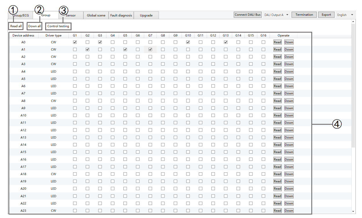
Fig.2.3 Group
① Read all: Click to read the grouping information for all drivers on the DALI bus and display it in DCA.
② Down all: Click to send all the configured groups to the corresponding DALI drivers.
③ Control testing: Click to send the current group configuration to the gateway, and enforce the corresponding drivers to their assigned group states.
④ Show all current driver addresses, driver types, and assigned group information.
Select to assign a group to the corresponding driver address.
Read: Click to read the group information of the specified driver address from the DALI bus and synchronize it with DCA.
Down: Click to send the group information to the corresponding driver.
2.4. Sensor
This gateway supports the connection of DALI input devices and can be configured with up to 8 sensor channels in ETS. It can synchronously read the input devices on the DALI bus and associate them with the sensors in ETS, enabling the reporting of DALI sensor data to the KNX system.
Currently, only motion sensors, brightness sensors, and motion + brightness 2-in-1 sensors are supported. All other input devices are displayed as “Other” device types.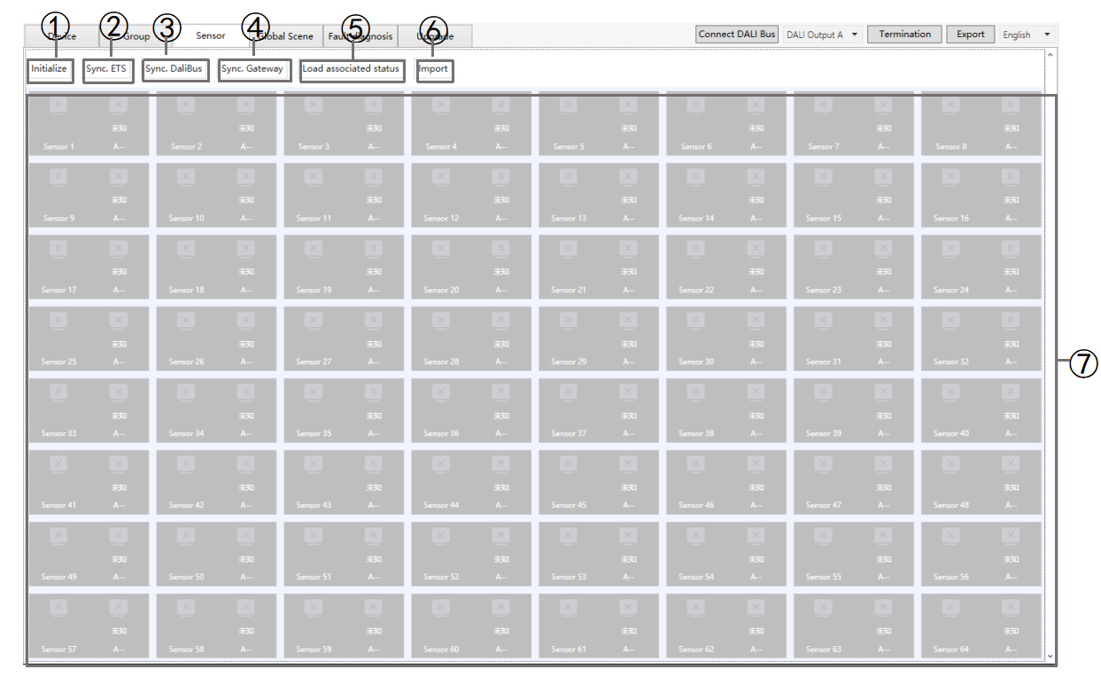
Fig 2.4 Sensor
① Initialize: Click to select “[All] init DALI device” or “[No Addr] init DALI device”.
[All] init DALI device: Initialize all sensor and assign DALI addresses to every sensor on the current channel.
NOTE:
This operation randomly reassigns addresses, which may disrupt the existing association between sensors and ECGs. Use with caution
[No Addr] init DALI device: Initializes only unaddressed sensors. Already assigned addresses remain unchanged.
NOTE:
If address allocation is incomplete, first perform [No Addr] init DALI device. If allocation fails more than twice, perform [All] init DALI device.
② Sync. ETS: Synchronize sensor configurations from ETS to DCA.
③ Sync.Dali Bus: Click to directly read the sensor configuration from the DALI bus.
NOTE:
If multiple sensors are present on the channel, this process may take some time.
④ Sync.Gateway: Click to read the saved sensor configuration from the gateway, including ETS and DCA configuration information. Missing information will result in empty data.
NOTE:
Ensure that the database has been downloaded before performing Sync Gateway. If the gateway has not received the DCA configuration, default settings may be reported, which may not reflect the actual situation.
⑤ Load associated status: Click to load the sensor configuration to the gateway.
NOTE:
If DCA has not read or configured driver parameters, they are not sent by default. After loading, you can re-read the configuration using Sync Gateway.
⑥ Import: Import a DALI gateway configuration. The imported data is displayed on this page, where you can modify and apply it. Double-left-clicking a device grid opens the detailed configuration page.
NOTE:
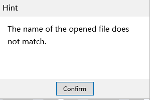
The imported file must be named SensorConfiguration.json. Otherwise, it cannot be imported, and the system will display a prompt as shown below

⑦ Display all sensors.
A. Double-left-click a device grid to open the detailed sensor page, where you can view the DALI device type/status, modify the address, and refresh brightness readings.
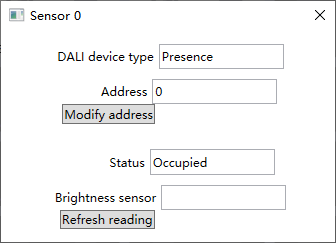
B. Modify ECG-sensor associations using any of the following methods:
Drag the grid to associate the sensor to the specified driver address.
Enter the specified driver address in the Sensor Details page and click “Modify address”.
NOTE:
The ECG type must match the sensor type of the corresponding address; otherwise, DCA will report an error.
Normal - Occupied (Fig.2.4(1)), No one (Fig.2.4(2)), and Moving (Fig.2.4(3)).
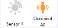
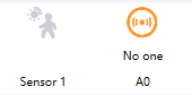
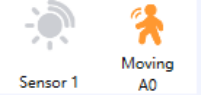
Fig.2.4(1)Occupied Fig. 2.4(2)No one Fig. 2.4(3)Moving
Error - Sensor not associated with a ECG:
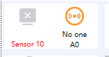
Error - ECG not associated with a sensor:
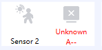
Error - Sensor not configured: The ECG is not linked to the address, and no sensor is configured at the corresponding address.
2.5. Global Scene
A global scene allows users to recall ECGs or groups as execution targets and set their target states. When the gateway receives a KNX scene control telegram on the bus, it performs the corresponding operations.
In the global scene interface, devices or groups can be added to a scene, and the target brightness, color temperature, and color for each device/group can be set. This provides more flexible and precise control, as shown in Fig. 2.5(1).
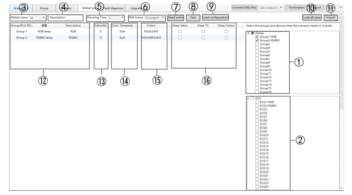
Fig.2.5(1) Scene
① Group: Display all groups. Click to select the group include in the scene, and click again to deselect.
NOTE:
16 groups are displayed by default. If no group description is displayed, click “Synchronize ETS Data” on the “Group/ECG” page.
② ECG: Display all lists obtained by DCA. Click to select the device to include in the scene, click again to deselect.
NOTE:
64 ECGs are displayed by default. If no ECG description is displayed, you can click “Synchronize ETS Data” on the “Group/ECG” page.
③ Global Scene: Select the scene number (1–16). Up to 16 scenes can be configured, each of which can include multiple groups or ECGs as execution targets. Each scene corresponds to a KNX scene number.
④ Description: Enter a description for this scene (up to 18 bytes).
⑤ Dimming time: Specify the fade duration for transitioning from the current state to the target state in the scene (Range: 0 - 255 seconds).
⑥ KNX scene: Select the KNX scene number that triggers this scene. When the gateway receives a scene number, the corresponding scene is executed. Up to 64 scene numbers are available.
⑦ Read scene: Click to read the configuration for the selected scene from the gateway and display it in the DCA. If it has not been loaded previously, the data will be empty.
⑧ Test: Click to send the selected scene configuration to the gateway for testing. Devices/groups will execute to the corresponding target states.
⑨ Load configuration: Click to send the selected scene configuration to the gateway.
⑩ Load all para.: Click to load the global scene configuration to the gateway.
NOTE:
This operation transfers a large amount of data and may take some time.
⑪ Import: Import a configuration of a DALI gateway. The imported data will be displayed on this page and can be modified or applied.
NOTE:
The file must be named SceneConfiguration.json. Otherwise, the import will fail and display the below message.

⑫ Group/ECG NO.: Display the group or ECGs to which the scene belongs, the ECG number, the driver type, and the description.
Description: Shows descriptions from ETS for the selected groups and devices. This data cannot be modified, and the gateway does not save it. If you click “Sync Gateway”, the data will be empty.
⑬ Value: Double-click to set the brightness for the device/group (0–100%), as shown in Fig. 2.5(2).
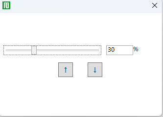
Fig.2.5(2) Brightness
⑭ Color temperature: Depending on the device type, this setting may be supported. Double-click to set the target color temperature for the device or group according to the ETS configuration. If unsupported, “N/A” is displayed, as shown in Fig. 2.5(3).
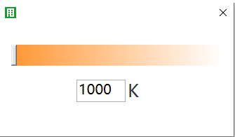
Fig.2.5(3) color temperature
⑮ Color: Depending on the device type, this setting may be supported. Double-click to set the target color for the device/group. If unsupported, “N/A” is displayed. Supported color types include RGB, RGBW, and XY, as shown in Fig. 2.5(4).
RGB RGBW XY
Fig.2.5(4) Color
⑯ Keep Value/Keep TC/Keep color: Check these options to retain the current brightness, color temperature, or color value, keeping the state before scene control.
NOTE:
All three options cannot be checked simultaneously.
2.6. Fault Diagnosis
On the DALI bus, faults are classified as either light faults or ECG faults. The DCA tool displays the total number of devices, fault counts and rates by type, overall fault statistics, and the status of each ECG and lamp. This information can also be exported, as shown in Fig. 2.6.
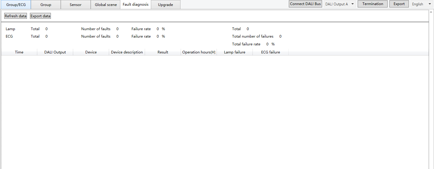
Fig.2.6 Fault diagnosis
2.7. Upgrade
The Upgrade interface allows you to view the DALI firmware version of the DALI gateway (see Fig. 2.7(1)) and perform firmware upgrades.
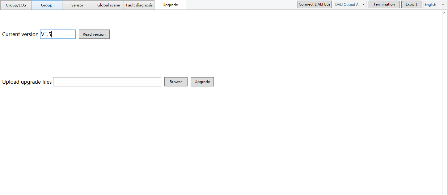
Fig.2.7(1) Read the DALI firmware version
Steps:
(1) Click “Browse” to select the upgrade file whose format is bin.XY
(2) Click “Upgrade” to start the process. The upgrade progress will be displayed (see Fig 2.7(2)).
(3) When the upgrade is complete, a message will appear: “Upgrade file issuance is complete.”
NOTE:
Do not perform other operations during the upgrade.
Click Cancel to stop the upgrade at any time.
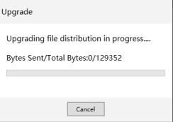
Fig.2.7(2) Upgrade