1. Functions
This KNX device is designed to control fans and valves, particularly in central heating and cooling systems. It supports both 230V AC motors and 24V AC motors with a 0-10V control interface, allowing for the control of heating, cooling, and fan speed settings (low, medium, high). Additionally, it can control lighting loads.
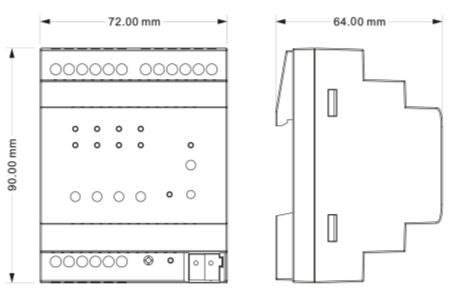
2. Dimensions
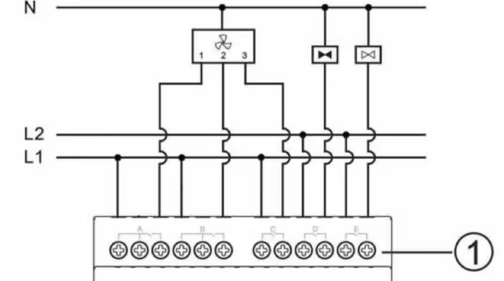
3. Circuit Diagram and Operating Elements
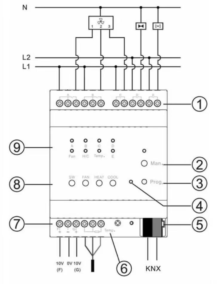
① 5 fold relay outputs: Can be set as fan speeds (A/B/C), valves (D for heating, E for cooling), or general switch outputs via parameter settings.
NOTE:
This mark
indicates that the two terminals are internally connected.
② Manual/Auto operation button: Press and hold for 1 second to switch modes. The indicator lights up when in manual control.
③ Programming button: Assign physical addresses.
④ Programming LED: Red LED for assigning the physical address, green LED for displaying application layer running normally.
⑤ KNX bus connecting terminals.
⑥ 3-wire PT1000 temperature sensor: Measure temperature.
⑦ 2 channel 0-10V output: Can be configured as fan speed or valve outputs via parameter settings.
⑧ Buttons: (From left to right) Switch control, fan speed, heating, and cooling.
Operations:
1)SW: Switch control button.
Long press to switch channels; short press to toggle the selected channel's on/off state.
Channel LED:
- Flashing: Channel is selected.
- Fast flashing: Relay contact is open.
- Slow flashing: Relay contact is closed.
2)FAN: Long press to turn off the fan; short press to switch fan speeds.
3)HEAT: Short press to switch on/off all heating valves.
4)COOL: Short press to switch on/off all cooling valves.
⑨ Output LEDs:
- A, B, C, D, E: Switch output status indicator (if the corresponding circuit set as a switch).
- Fan: Red for Speed 1, green for Speed 2, blue for Speed 3.
- H/C: Red for Heating, blue for cooling.
- Temp.: Light up for temperature detection errors.
4. Parameter Settings in ETS
NOTE:
This product is available in the ETS online catalog. If it is not listed, please contact akubela technical support for its database.
Interface Setting
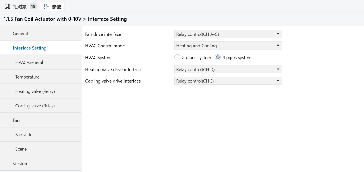
Fan drive interface: Select the drive interface for the fan.
Options:
- Relay
- 0-10V
HVAC Control mode: Set the HVAC control mode.
Options:
- Disable: Deactivate HVAC.
- Heating: Fan coil supports heating only.
- Cooling: Fan coil supports cooling only.
- Heating and cooling: Fan coil supports both heating and cooling.
HVAC System: Set the type of piping for the fan coil’s water inlet and outlet.
Options:
- 2-pipe system: Heating and cooling share the same inlet and outlet pipes, controlled by a single valve.
- 4-pipe system: Separate pipes for heating and cooling, with independent valves for hot and cold water control.
Heating/Cooling value drive interface: Select the interface for heating/cooling valve.
Options:
- Relay
- 0-10V
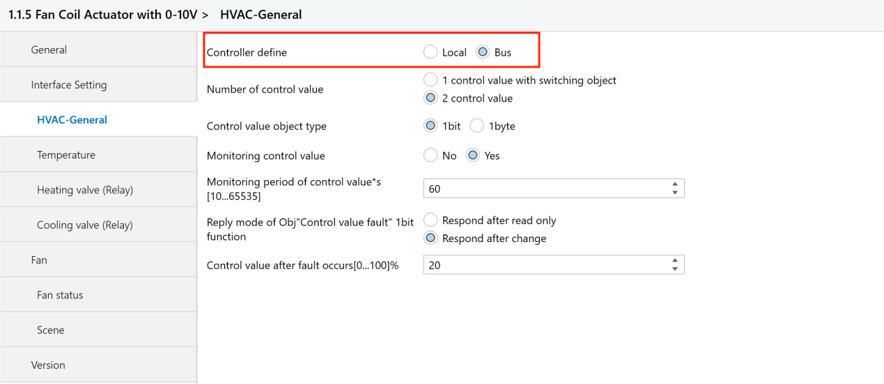
HVAC-General
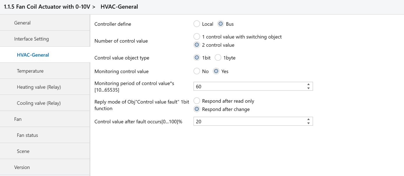
Control define: Set the source of the fan coil controller.
Options:
- Local: The fan coil is controlled by this actuator’s output, acting as the master device to control the valve.
- Bus: The fan coil is controlled by an external controller input, with this actuator acting as the slave device. The valve is controlled by external devices (e.g., a thermostat panel).
Number of Heating/Cooling switch object: Select the control method for the group objects.
Options:
- 1 control value with switching object
- 2 control value
Control value object type: Set the data type for controlling heating and cooling.
Options:
- 1bit
- 1byte
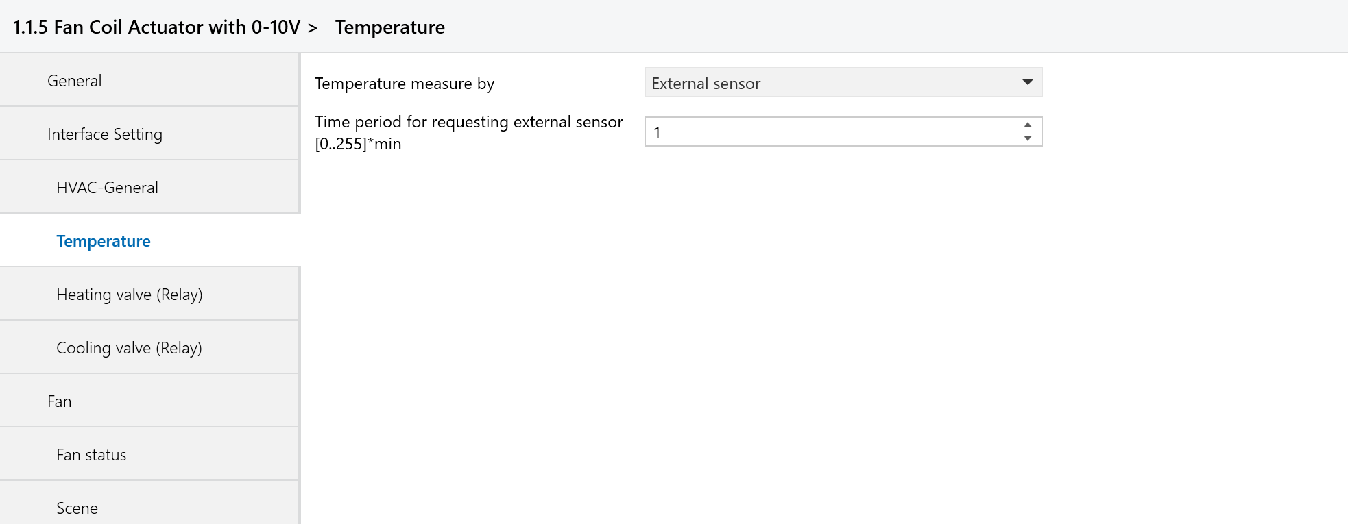
Temperature

Temperature measure by: Select the sensor used to collect the temperature.
Options:
- Local sensor: Temperature data is collected by this actuator.
- External sensor: Temperature data is collected by another device on the bus.
- Local and External sensor combination: Temperature data is collected using both the actuator's sensor and an external sensor.
Heating/Cooling value (Relay)
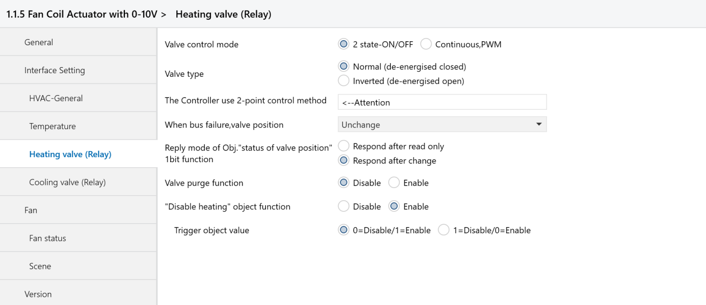
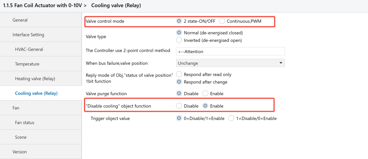
Value control mode
Options:
- 2 state-ON/OFF
- Continuous, PWM(Pulse Width Modulation)
Valve type: Set the valve switch direction, either normally closed or normally opened.
Options:
- Normal (de-energised closed)
- Inverted (de-energised open)
Disable heating/cooling object function: Disable the heating/cooling valve(used to forcibly close the valve).
Options:
- Disable
- Enable
Fan
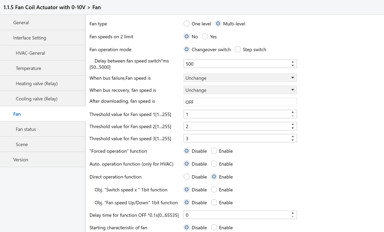
Fan type: Select the type of fan to control.
Options:
- One level: Control 1-speed fans only.
- Multi-level: Control up to 3-speed fans.
Fan speeds on 2 limit: Choose whether to limit fan speed to only 2 levels.
Options:
- No: No limit, fan speeds can be controlled at levels 1, 2, and 3.
- Yes: Fan speed is limited to levels 1 and 2.
Fan operation mode
Options:
- Changeover: This mode allows switching directly between fan speeds (e.g., from level 1 to level 3), with only one output active at any time.
- Step: Fan speeds are achieved by combining outputs. For example, at speed 3, all three outputs (CH A, B, C) are active; at speed 2, two outputs (CH A, B) are active.
Threshold value for Fan speed 1/2/3:Set the control values for each fan speed level to match the fan speed settings in the HyPanel.
Fan status
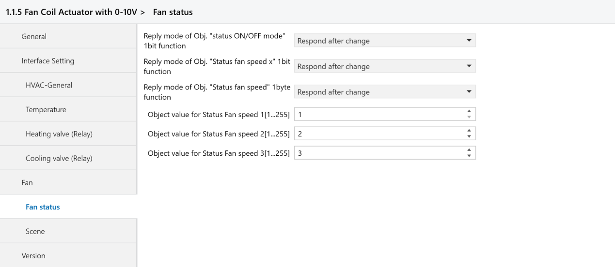
Object value for Status Fan speed 1/2/3:Set the fan speed status value to be sent, ensuring it matches the value in the HyPanel.
5. Application Example
Case: Central Air Conditioning System Settings for Office
Background
The office area is 500 square meters, divided into multiple independent zones.
Each zone requires independent temperature and fan speed control.
Use a centralized fan coil system for heating and cooling.
Requirements
Enable independent temperature control for each zone.
Provide multiple fan speed options to enhance comfort.
Support scene setting for customized climate control.
Installation and Configurations
(1) Installation
Install the KNX fan coil module in the central control cabinet in the equipment room.
Ensure that each fan coil unit is connected to the corresponding temperature control panel in each zone.
(2) Wiring
Follow the wiring diagram to connect the fan coil module to each fan and valve.
NOTE:
Only a live wire is needed.
B. Secure wiring to prevent signal loss.
(3) Configuration in ETS
1) Project Preparation
Create a New Project
① Open the ETS software and select New Project.
② Enter the project name and description, then click OK.
2) Network Topology Setup
A. Create a Main Line and Area Lines
① In the ETS project, create a main line 1.0.
② Under it, add area line 1.1 for office.
B. Create Additional Lines
Under line 1.1, create lines for specific zones (e.g., line 1.1.1 for Meeting Room A) to connect KNX devices.
3) Device Addition and Configuration
A. Import Device Database
① Click Import Project, then select and import the database files of the fan coil module and HyPanel.
.png)
.png)
② Verify that the imported data appears under Topology.
.png)
B. Add Devices
In the office B (1.1), drag the fan coil module and HyPanel from the product catalog and imported database into the topology.
C. Device Parameter Settings
Fan Coil Module Settings
 Fan drive interface: Select “0-10V”. HVAC Control mode: Select “Heating and Cooling”. HVAC System: Select 2-pipe or 4-pipe based on project requirements. Here, “4-pipe system” is chosen.
.png)
![]() Controller define:Select “Bus” to control via the HyPanel.
Controller define:Select “Bus” to control via the HyPanel.
![]() Temperature measure by: Select External sensor for measuring temperature by other devices in the main line.
Temperature measure by: Select External sensor for measuring temperature by other devices in the main line.
![]() Fan type: Select “Multi level” to control fan speeds at multi levels.
Fan type: Select “Multi level” to control fan speeds at multi levels.
![]() Fan speeds on 2 limit: Select “No” to control fan speeds at 1, 2 and 3 level.
Fan speeds on 2 limit: Select “No” to control fan speeds at 1, 2 and 3 level.
![]() Fan operation mode: Select “Changeover”.
Fan operation mode: Select “Changeover”.
![]() Threshold value for Fan speed 1/2/3: Set the output value for each fan speed to match HyPanel’s settings.
Threshold value for Fan speed 1/2/3: Set the output value for each fan speed to match HyPanel’s settings.
![]() Starting characteristic of fan: The fan’s starting speed level, select “Disable”.
Starting characteristic of fan: The fan’s starting speed level, select “Disable”.
.png)
HyPanel Settings
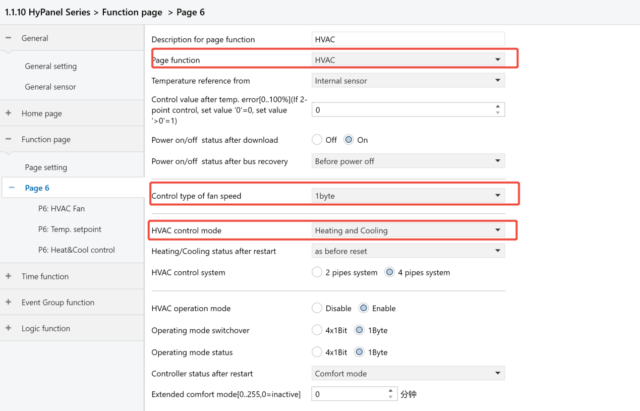
Page function: Select “HVAC”. The page can be 6-15. Control type of fan speed: Select “1byte”. NOTE:
When using HyPanel to control the fan coil module, this parameter ” control type of fan speed” must be set to 1byte. Selecting 1bit may cause issues.
HVAC control mode: Select “Heating and Cooling”.
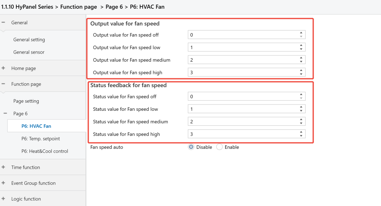
![]() Output value for fan speed: Set the value to match the fan coil module's threshold value.
Output value for fan speed: Set the value to match the fan coil module's threshold value.
![]() Status feedback for fan speed: Set the value to match the fan coil module's threshold value.
Status feedback for fan speed: Set the value to match the fan coil module's threshold value.
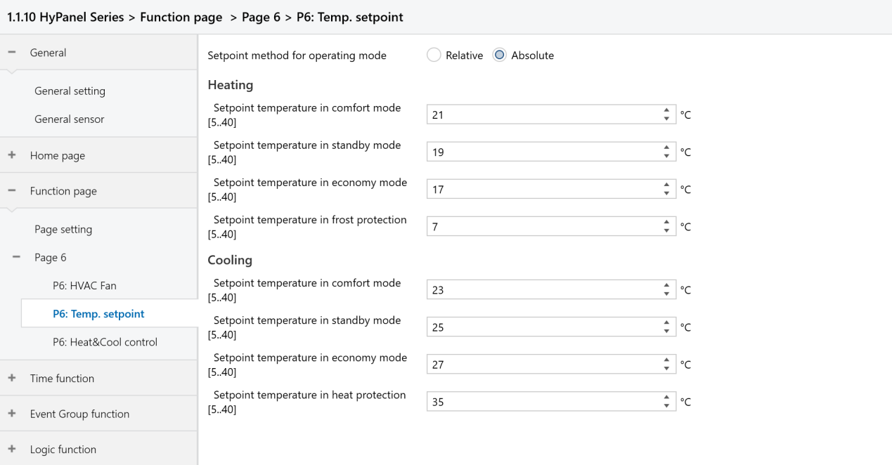
![]() Configure the setpoint temperature values and operating modes for Heating and Cooling.
Configure the setpoint temperature values and operating modes for Heating and Cooling.
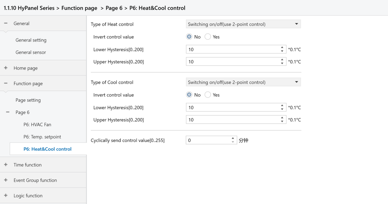
![]() Set the control types and hysteresis temperature.
Set the control types and hysteresis temperature.
4) Scene Configuration
Away Mode Configuration
Configure the scene of away mode: When there is no person in the office, the air conditioning will automatically turn off.
![]() Enable the Scene function for the fan coil module
Enable the Scene function for the fan coil module
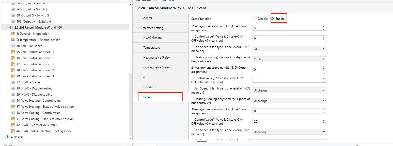
![]() Enter the scene number and set the fan speed as off.
Enter the scene number and set the fan speed as off.
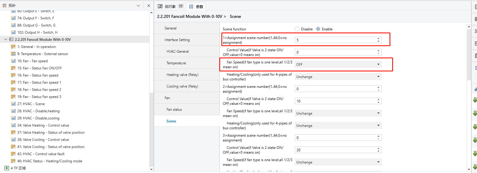
![]() Align the scene number on the fan coil module with the corresponding scene number on the HyPanel.
Align the scene number on the fan coil module with the corresponding scene number on the HyPanel.
.png)
![]() Link group addresses.
Link group addresses.
.png)
.png)
5) Assign and Link Group Address
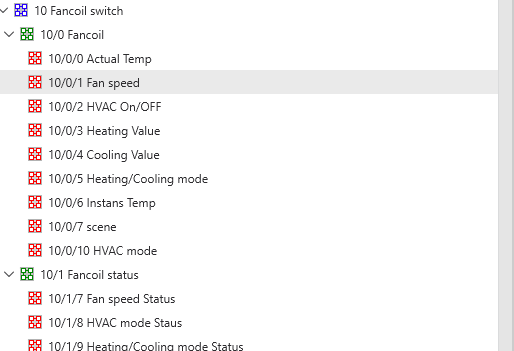
A. Create Group Addresses
In ETS, click Group Addresses tab.
Create group addresses:
HVAC On/OFF: Turn the HVAC on/off. Actual Temp.: Obtain temperature from the internal temperature source. Set Temp.: Send setpoint temperature value. Fan Speed: Control fan speed; its data type must be 1 byte. Fan Speed Status: Read fan speed status; its data type must be 1 byte. Heating Value: Turn the heating valve on. Cooling Value: Turn the cooling valve on. Heating/Cooling Mode: Switch heating and cooling modes. Heating/Cooling Mode Status: Read the heating/cooling mode switching status. HVAC Mode: Control the functions for heating/cooling modes. HVAC Mode Status: Obtain the status of the functions in heating/cooling modes.
B. Assign Group Addresses
Return to the Topology and select the communication objects of devices.
Link the group addresses of the HyPanel with the corresponding group objects of the fan coil module.
.png)
.png)
6) Download Project Data to Devices
① Ensure all devices are properly connected and powered on.
② Select the fan coil module and click Download to transfer the ETS project data.
③ Repeat the download process for the HyPanel to transfer the data to it.
.png)
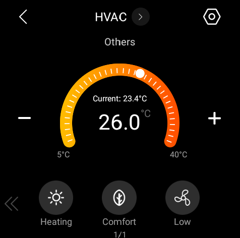
Once downloaded, the screens for controlling HVAC on the HyPanel is shown below.
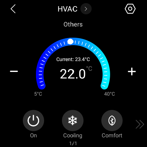
![]()
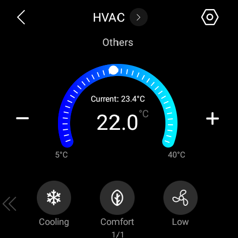
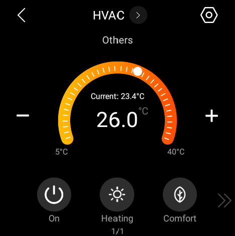
![]()