SCR Dimming Actuator, 4-Fold, 300W (KXAC-B1D4P300)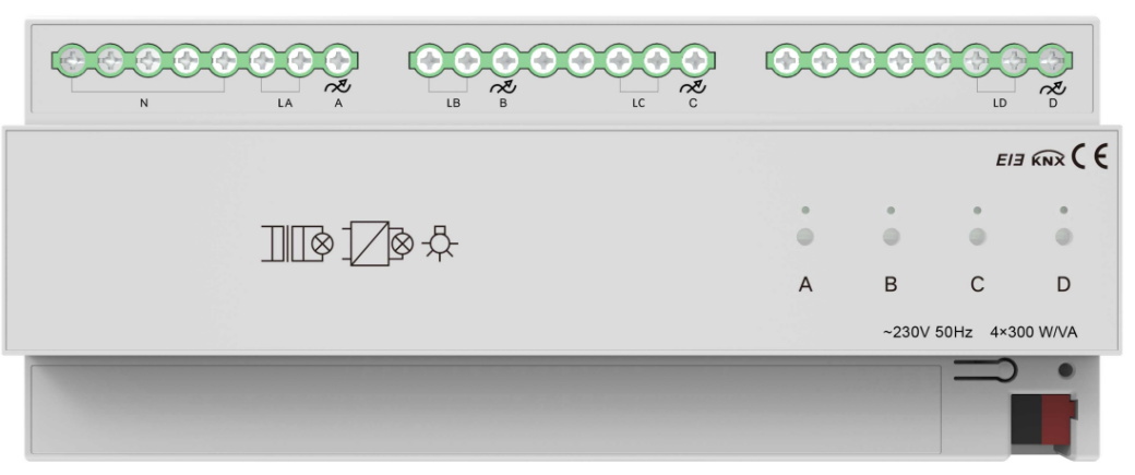
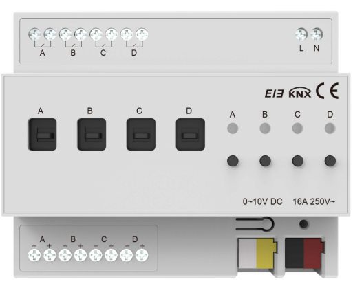
Dimming Actuator, 4-Fold, 0-10V (KXAC-B1DV4)
1. Application overview
The dimmer application configures parameters for each output channel, controlling objects by adjusting internal parameter settings.
1.1 Switch
1-bit data
The switch state of the lights is controlled by a 1-bit data. Brightness can be restored to the last value or set to a preset (1%-100%) when turned on. It is able to set a delay time(changing time) to dim up a light, or to gradually increase brightness over the default changing time. Upon receiving the off telegram, the dimmer turns off immediately, or dim down gradually after the delay time or over the default changing time.
1.2 Relative dimming
4-bit data
Relative dimming adjusts brightness up or down within a specified threshold range. It is valid only when dimming up below the low threshold and dimming down above the high threshold. The dimmer can also be set to either turn off the light or maintain the low threshold brightness when the relative dimming results in a value less than or equal to the low threshold. Also, it enables setting whether to switch on the lights with a “Dim up to a certain value" telegram when the output is 0.
Relative dimming controls the relative change of brightness by 4-bit data. The lowest three bits are control bits, while the highest bit indicates the up and down: “1” for dimming up and “0” for dimming down.
Relative dimming settings:
■ 1~7: Dim down
■ 0 and 8: Remain unchanged/stop dimming
■ 9~15: Dim up
Parameter Value | 0 | 1 | 2 | 3 | 4 | 5 | 6 | 7 |
Dim Down | No change/ stop dimming | 255 | 128 | 64 | 32 | 16 | 8 | 4 |
Parameter Value | 8 | 9 | 10 | 11 | 12 | 13 | 14 | 15 |
Dim Up | No change/ stop dimming | 255 | 128 | 64 | 32 | 16 | 8 | 4 |
1.3 Brightness
8-bit data
The dimmer adjusts the brightness to the desired level by changing the brightness parameter. The brightness parameter setting is similar to relative dimming and allows for setting a brightness range with low and high thresholds. Brightness can only be adjusted within this range, with a maximum adjustable range of 0 to 255. When turning on, the light can gradually brighten to the target brightness after a delay or within the default time. When turning off, it can gradually dim down to 0 state within the delay or default time.
The threshold values limit the total output range of the dimmer. Any brightness value outside this threshold range is not valid.
When the brightness is 0, the dimmer can be set to either turn off the light or maintain the low threshold brightness. In this state, it is also optional to set to switch on the lights upon receiving an "absolute dimming" command.
1.4 Status report
1-bit data
The dimmer can set to whether to send the latest brightness value of target objects and the updated switch status report to the BUS.
1.5 Scenes
8-bit data
The dimmer provides 15 scenes (numbered 1 to 15), each with configurable brightness and gradual changing time. Once set, any scene can be called at any time. When the highest bit of the scene command is 1, it acts as a “saving” command, updating the current brightness to the selected scene.
1.6 Preset values
1-bit data
The dimmer can pre-configure scenes.
The object can use 1-bit data to call a preset scene or replace the scene with a favorite one. Each channel has two preset values, with two brightness settings per preset. For instance, in a theater, you might use the first brightness value for bright lighting upon entry and the second for dim lighting during the movie. After the movie, you can return to the previous brightness setting.
1.7 Staircase light
Dimmers can also be applied to staircase lighting control.
The staircase lighting function can switch off the lighting directly until the brightness dims down to 20% after a set period. The brightness level, the duration of the light, and the time to dim to 20% can all be set respectively.
The dimming system uses a 1-bit data control to set a permanent fixed value for the staircase lighting output.
Switching control process
■ If the switch object receives a "1" telegram, the dimmer will keep the staircase light on for a configurable period. If another "1" telegram is received during this time, the light remains on. After the duration ends, the light will gradually dim to 20% brightness before turning off (dimming time configurable). Alternatively, receiving a "0" telegram will cause the light to gradually dim to 20% before turning off (dimming time also configurable).
■ If a fixed switch object receives a "1" telegram, the staircase lighting will maintain a configurable brightness level until a "0" telegram is received. Upon receiving a "0" telegram, the light will gradually dim to 20% brightness (dimming time as previously configured). If the system's setting "Turn off when switch object is 0" is enabled, the switch can either turn off the output in the fixed brightness state or switch to a permanent lighting mode at the fixed brightness level. ("1" indicates ON, and "0" indicates OFF.)
1.8 Bus reset
In the event of a bus power failure, the dimmer will turn off all outputs, and the current brightness value is saved in the dimmer’s memory. When bus power is restored, the current brightness state may either be the last brightness value or a preset brightness value.
When the BUS is power off, the following may occur:
In the normal mode: The action after a bus power recovery can either be the brightness value before power off, or the preset value.
In the staircase mode: The action after a bus power recovery can either be on or off. No output when it is off. If on, it will execute the “switch=1" action.
1.9 Error report
It is used to report the system's error status. The data type is 1 byte, and the distribution is as follows:
Data bit | Bit0 | Bit1 | Bit2 | Bit3 | Bit4 |
Target | Channel 1 | Channel 2 | Channel 3 | Channel 4 | —— |
Function | Short circuit, overload | Short circuit, overload | Short circuit, overload | Short circuit, overload | Heat sink Temperature > 70°C |
1.10 Device normal operation indicator
When operating normally, the sign periodically sends telegrams to the bus to report its correct functioning.
2 ETS system parameter settings
2.1 Overview
The dimmer provides two operation modes for each output channel:
Normal dimming
The normal dimming mode is used to control common lighting systems, allowing for setting dimming output time and brightness values, dimming up and down with relative dimming function, and calling preset brightness values through scene functions to achieve the desired ambiance.
Staircase lighting
Staircase light mode controls lights by turning them on for a set delay before automatically turning off. They can also stay on longer but must be manually turned off.
2.2 Parameter settings “Device general”
The parameter settings for different devices may vary. If a device's parameters don't include the ones described below, it won't support the associated functionality.
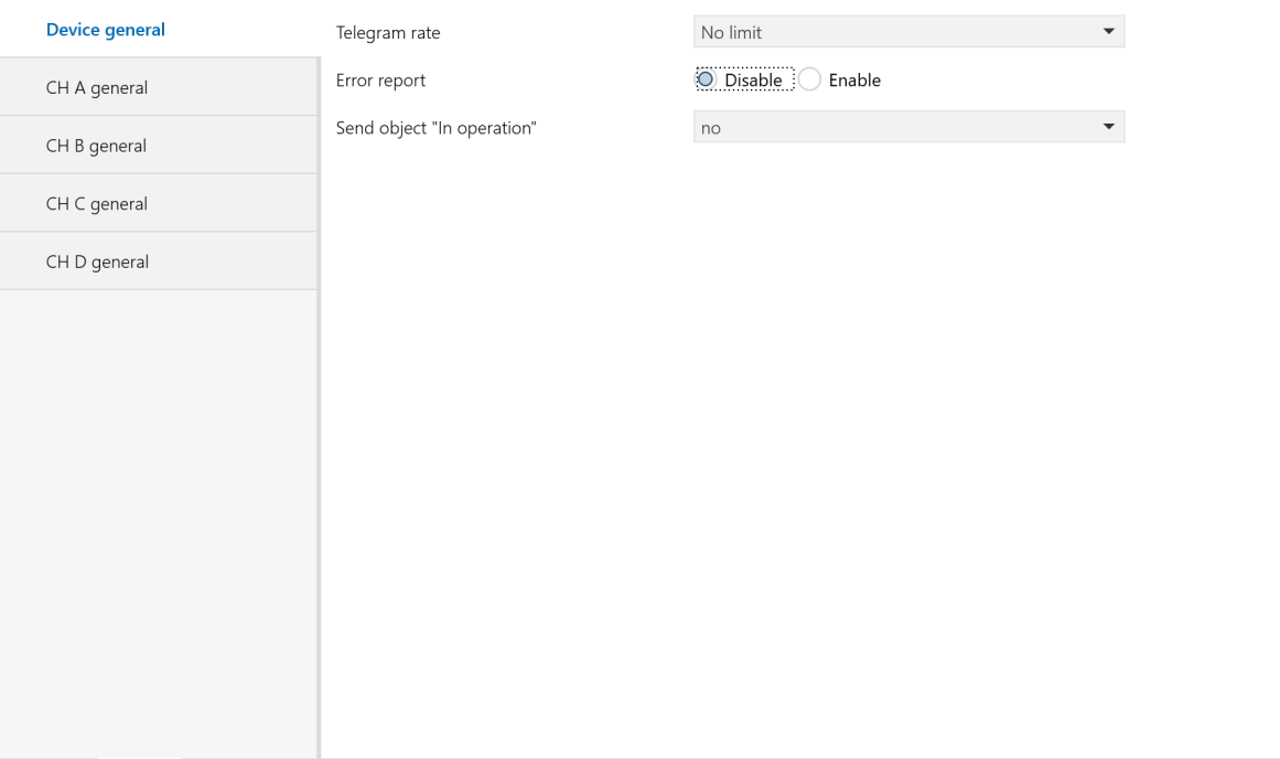 Figure 2-1: Device general setting interface
Telegram rate
Set the frame rate.
Options:
No limit
Delay 100ms
Delay 200ms
......
Delay 700ms
In this system, the frame rate function is not enabled. Please select “No limit”.
Error report
Set whether to report the system's error status, controlled by 1 byte of data bit.
Options:
Disable: The system will not report errors when they occur.
Enable: The system will report errors when they occur. if the device overheats, is overloaded, or experiences a short circuit, it will trigger an alarm and automatically shut down. In the event of an output overload or short circuit, the hardware will shut down the output and report an error. Once the output is turned off via the bus or the issue is resolved, the output will return to its normal state.
For a universal dimmer, the temperature stabilization time is set to 1 minute. If the temperature exceeds 70°C for 1 minute, the output brightness is reduced to 30% of the current setting. When the temperature drops to 60°C for 1 minute, the output brightness is restored to 50% of the current setting. If the temperature exceeds 90°C for 1 minute, the output is turned off and cannot be turned back on until it cools down and is restarted. If there are fluctuations around critical temperature points, the stabilization timer resets.
For a 4A LED dimmer, when the heatsink temperature exceeds 70°C, the LED brightness decreases by 5% for every 1°C increase. If the temperature continues to rise, the brightness continues to decrease, and at 80°C, the output is turned off.
Sending cycle time in s[1...65535]
Define the time interval at which the dimmers send error reports via the bus. The reporting interval starts once error reporting is enabled.
Options:1.....65535s
Send object “In operation”
Periodically send telegrams of "1" or "0" to the bus to check if the device is working or not.
Options:
No:Do not send.
send value “0” cyclically
send value “1” cyclically
The following parameter will appear when selecting “send value “0”cyclically” or “send value “1”cyclically” option. It defines the time interval for sending the telegrams.
Sending cycle time in s[1...65535]
Set the time interval at which the dimmer sends telegrams via the bus to report if it is working normally.
Options:1.....65535s
2.3 Parameter settings “CH X active”
The “CH X active” parameter settings interface is shown in Figure 2-2. This interface allows you to enable or disable the X channel output of the dimmer.
In the following descriptions, “CH X” or “X” refers to a dimmer output. Each channel has the same settings and objects; the explanation uses one channel as an example.
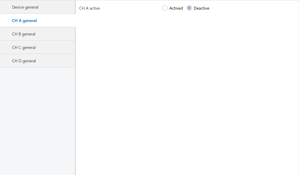
Figure 2.2: CH X active setting interface
CH X active
Options:
Actived: Enable dimmer X channel. Selecting this option displays the interface shown in Figure 2-3, where you can set the dimmer’s working mode, current brightness, and switch status reporting.
Deactive: Do not use this channel.
2.4 Parameter settings “CH X gernal”
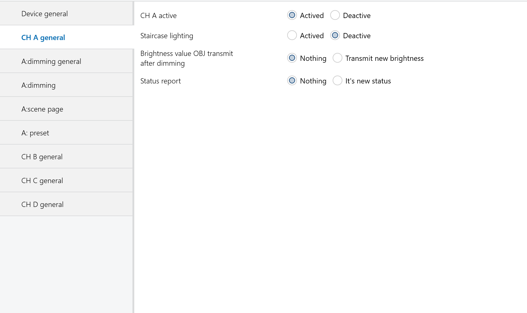 Figure 2-3: CH X general setting interface
Staircase lighting
Options:
Actived: Enable the staircase light mode for the channel X.
Deactive: Normal dimming mode.
Brightness value OBJ transmit after dimming
Report the latest brightness value. When enabled, a frame will be sent to the bus no matter what happen to make the brightness value changed.
Options:
Nothing: Do not report the current brightness status.
Transmit new brightness: When a brightness adjustment telegram is received, a frame will be sent to the bus to report the current brightness value, even if it has not changed.
Note:
When the option “transmit new brightness" is selected, the objects “Brightness status X" and “Brightness X" should not be linked to a same group address. Doing so can create an internal loop, causing an endless loop and potentially crashing the system.
Status report
Set whether the current switch state should be reported to the bus when the "switch" object changes. The switch state sends “1" to the bus when the brightness value is greater than 0; it sends “0" when the brightness value is 0.
Options:
Nothing: Never send the current switch state to the bus.
It ’s new status: Report the switch state change to the bus.
Note:
When the option “It's new status" is selected, the objects “Switch status X" and “Switch X" should not be linked to a same group address. Doing so can create an internal loop, causing an endless loop and potentially crashing the system.
2.5 Normal dimming mode
2.5.1 Parameter settings “X: dimming general”
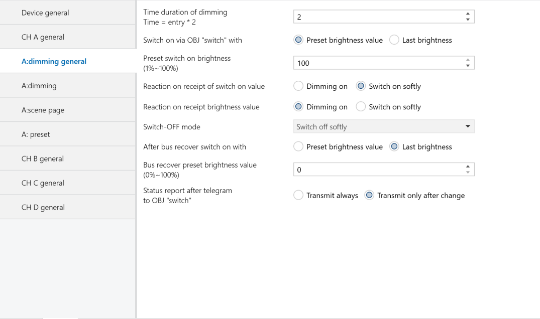 Figure 2-4: X: dimming general setting interface
Time duration of dimming time=entry * 2
Set the dimming time for both brightness and switch dimming modes. The dimming on or off time is calculated as the input value multiplied by 2 seconds, with a maximum allowed input of 255 seconds.
Switch on via OBJ “switch” with
Define when turning on the light using the switch mode, the brightness value should be the last or a preset brightness value.
Options:
Preset brightness value: When turning on the light via switch mode, the brightness will be the value preset in the parameter “Preset switch on brightness (1%~100%)". If the preset value is below the minimum brightness threshold, the light will turn on at the minimum brightness. If the preset value exceeds the maximum brightness threshold, the light will turn on at the maximum brightness. The brightness thresholds are configured in the "CH X dimming" parameter settings, as described in the "CH X dimming" section.
Last brightness value: When turning on the light, the brightness will be the last status’ value which is not equal to 0. If the light is turned on in switch mode after a bus reset and is off after the reset, the default brightness value will be 128.
Preset switch on brightness(1%~ 100%)
Set the brightness value when turning on the light using the switch mode. The brightness range is from 1% to 100%.
Reaction on receipt of switch on value
Define the time to turn on the light using the switch mode.
Options:
Dimming on: The dimming time is the input value in the above parameter “time duration of dimming time = entry * 2" multiplied by 2.
Switch on softly: The dimming time is 4 seconds by default.
Reaction on receipt brightness value
Define the time to turn on the light in the brightness dimming mode.
Options:
Dimming on: The dimming time is the input value in the above parameter “time duration of dimming time = entry * 2" multiplied by 2.
Switch on softly: The dimming time is 4 seconds by default.
Switch-off mode
Define the time to turn off the light in the switch mode.
Options:
Dimming off: The dimming time for turning off is the input value in the above parameter “time duration of dimming time = entry * 2" multiplied by 2.
Switch off softly: The dimming time is 4 seconds by default.
Switch off instantly: The light turns off immediately.
After bus recover switch on with
Under normal conditions, after a BUS reset, the brightness will either revert to the value before power off or to the preset value.
Options:
Preset brightness value:
Upon bus power recovery, the brightness will be set to the “bus recover preset brightness value (0%–100%)”. If this preset value is lower than the minimum brightness limit, the brightness will be adjusted to the minimum limit. If the preset value exceeds the maximum brightness limit, it will be set to the maximum limit. The minimum and maximum brightness limits are configured in the CH X dimming settings interface, as shown in Figure 2.5.
Last brightness value: After bus power recovery, the brightness will be set to the last value before power off. Additionally, a bus reset operation will be performed after downloading the parameters.
Bus recover preset brightness value(0%~ 100%)
Set the brightness level upon bus power recovery, with a brightness range of 0% to 100%.
Status report after telegram to obj “switch”
Backup parameter. Leave it unconfigured.
2.5.2 Parameter settings “X: dimming”
The “CH X dimming" parameter settings interface, as shown in Figure 2-5, configures parameters for the brightness dimming mode. There are two types of brightness dimming mode: Relative dimming and brightness value.
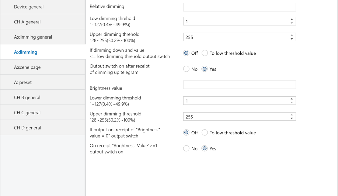 Figure 2-5: X: dimming setting interface
Relative dimming:
Low dimming threshold 1 ~ 127(0.4% ~ 49.9%)
Set the low limit for relative dimming. When the brightness is below this threshold, it can only be dimmed up. The range is from 1 to 127 (0.4% ~ 49.9%). For example, if the low limit is set to 50, and the current brightness is below 50, you can only increase the brightness until it is higher than 50 before you can dim it down again.
Upper dimming threshold 128 ~ 255(50.2% ~ 100%)
Set the low limit for relative dimming. When brightness is below this threshold, only dimming up is allowed. The range is from 1 to 127 (0.4% to 49.9%). For example, if the low limit is set to 50 and the current brightness is below 50, you can only increase the brightness above 50 before dimming down again.
If dimming down and value <=low dimming threshold output switch
Decide whether to turn off the light or maintain it at the low limit when brightness is at or below the low threshold after relative dimming.
Options:
Off: The light will turn off when the brightness is dimmed down to the low threshold value.
To low threshold value: The brightness remains at the low threshold value even when dimming further below this limit.
Note:
Whether set to "Off" or "To low threshold value," if the low threshold for relative dimming is lower than the brightness low threshold, the lights will automatically turn off when dimmed down to the brightness low threshold. If the brightness high threshold is lower than the relative high threshold, relative dimming can only increase up to the brightness high threshold. (These thresholds limit the dimmer's total brightness range; see details below.)
Output switch on after receipt of dimming up telegram
Define whether the light can be turned on when receiving a “dimming up" telegram from relative dimming while the output is at 0.
Options:
No: If the current output is 0, it remains at 0 even when a “dimming up” telegram is received.
Yes: When the target receives a "dimming up" telegram, the output increases to the new brightness value. If this new value is below the low threshold, the output will be set to the low threshold. If it exceeds the high threshold, the output will be set to the high threshold.
Brightness value:
The high and low threshold values limit the maximum and minimum output levels. Any brightness value outside these thresholds will be invalid. For example, in Figure 2.5, if the range is set to 1~255, and the low threshold is set to 50 and the high threshold to 200, a brightness value of 210 will be invalid. The lights will start dimming from the low threshold when increasing from 0, and from the high threshold when decreasing from 255.
Low dimming threshold 1~ 127(0.4%~49.9%)
Set the dimmer's low threshold, which ranges from 1 to 127. Dimming will start from this threshold. For example:
If the current brightness is 0 and the low threshold is 50 with a high threshold of 200:
❖ A telegram of target value 30 will directly set the brightness to 50 without the gradual change.
❖ A telegram of target value 60 will first adjust the brightness to 50, then gradually increase it to 60.
If the current brightness is 100 and when receiving telegram of target value 30, it will dim to 50 and stay there.
Upper dimming threshold 128~255(50.2%~ 100%)
Set the high limit for brightness dimming within a range of 128 to 255. For example, if the low limit is set to 50 and the high limit to 200, any input brightness value above 200 will be output as 200.
If output on: receipt of “brightness value=0” output switch
Define whether the specified brightness value of 0 can be used to turn off the output.
Options:
Off: When the specified brightness value is 0, the output will be 0.
To low threshold value: When the specified brightness value is 0, the output will be set directly to the low threshold value.
On receipt“brightness value ”>=1 output switch on
Define whether the output can be turned on using the brightness dimming mode when the output is 0.
Options:
No: When the output is 0 and a telegram of 100 is received, the dimmer will remain an output of 0.
Yes: When a brightness value greater than or equal to 1 is received, the output will be set directly to the received brightness value. If the received brightness value is below the low limit, the output will be set to the low limit value.
2.5.3 Parameter settings “X: scene page”
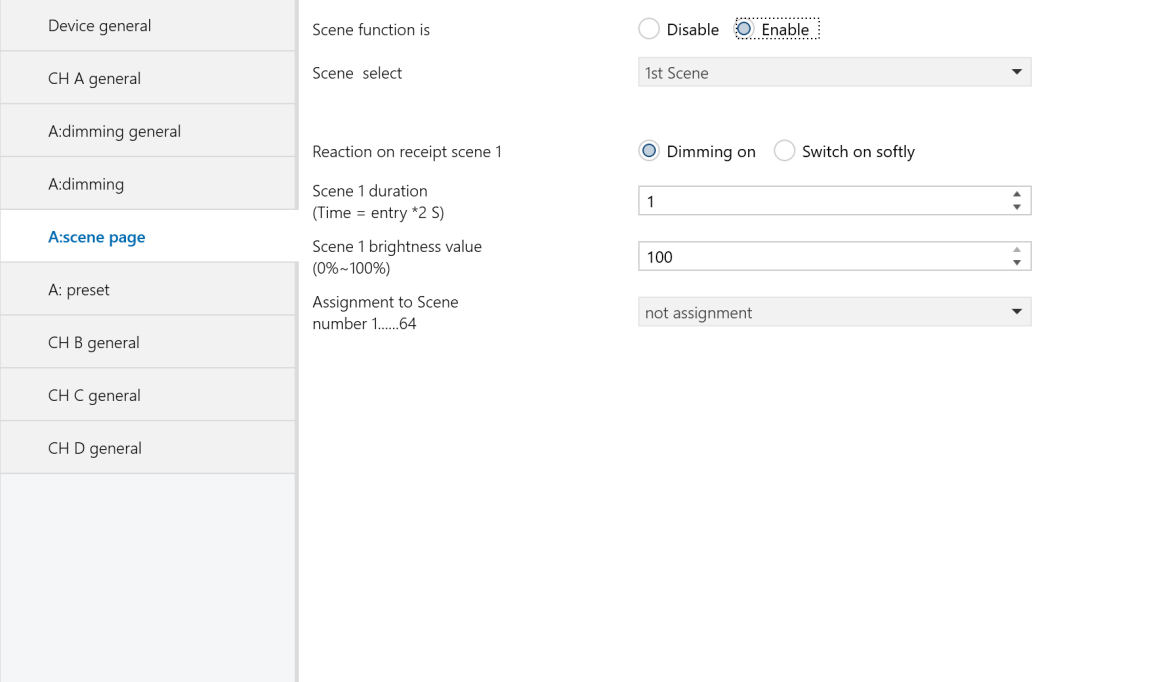 Figure 2-6: X: scene page setting interface
This interface allows configuration of up to 15 scenes (numbered 1 to 15). All scenes can be configured at once and called directly via the control panel when needed.
Scene function is
Enable or disable the scene functionality.
Options:
Enable
Disable
Scene select
Select the scene to be configured, allowing for setting the brightness, dimming time, and dimming mode for each scene.
Options:
1st Scene
2nd Scene
......
15th Scene
The brightness, dimming mode, and dimming time for the 15 scenes are configured in the following parameters.
Reaction on receipt scene Y
Set the dimming mode for the selected scene. Y represents the scene number (1 to 15), and this designation is used consistently in the following descriptions.
Options:
Dimming on: The dimming time for the selected scene is the time set in the parameter “Scene Y duration (time = entry * 2s)," which is the input time multiplied by 2.
Switch on softly: The dimming time for the selected scene is 4 seconds by default.
Scene Y duration(time=entry*2s)
Set the dimming time for the selected scene. The time is calculated as the input value multiplied by 2 seconds, with a maximum allowable input time of 255s.
Scene Y brightness value(0%~ 100%)
Set the brightness of the scene, with a brightness range of 0% to 100%.
Assignment to Scene number 1...64
Assign a scene number to the configured scene. The communication object “Scene/save X" will call the scene using the assigned scene number.
Options:
Not assignment
Assignment to scene 1
Assignment to scene 2
...
Assignment to scene 64
Note:
The parameter setting options are scene numbers from 1 to 64 or unassigned.
2.5.4 Parameter settings “X:preset”
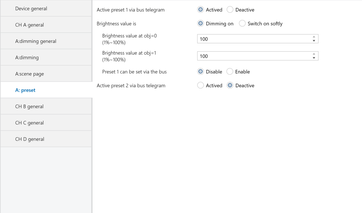 Figure 2-7: X: preset setting interface
The “X preset” settings interface, shown in Figure 2-7, allows for configuring two preset values (preset 1 and preset 2), each with two distinct brightness levels. These presets enable predefined lighting effects and can be activated via the communication object (X preset 1). Additionally, the current brightness state can be saved as a new preset value via the bus. Both preset values share the same parameters; the following description will focus on one preset as an example.
Active preset 1 via bus telegram
This parameter is used to activate preset 1.
Options:
Active
Deactive
The following parameters will appear when selecting “Active”.
Brightness value is
Defines the time for starting dimming with “preset 1”. It uses 1-bit data to control “X preset 1”, with values “0” and “1” to select between two different brightness levels.
Options:
Dimming on: The dimming time for the object “X preset 1" will be the time set in the parameter “Time duration of dimming Time = entry" multiplied by 2.
Switching on softly: The dimming time for the object “X preset 1" is 4 seconds by default.
Brightness value at obj=0(1%~100%)
Set the brightness value for object “X preset 1" when it receives a “0" telegram.
Options:1~100%.
Brightness value at obj=1(1%~100%)
Set the brightness value for object “X preset 1" when it receives a “1" telegram.
Options: 1~100%.
Preset 1 can be set via the bus
Define whether the preset values can be modified via the bus.
Options:
Enable
Disable
When "enable" is selected, it allows preset values to be modified via the bus, and the communication object “Set preset 1” is activated. This communication object saves the current brightness state as a new preset value.
If it receives a "0" telegram, the current brightness is saved to the parameter “brightness value at obj=0”, replacing the existing value.
If it receives a "1" telegram, the current brightness is saved to the parameter “brightness value at obj=1”, replacing the existing value.
2.6 Staircase lighting mode
When the staircase lighting mode is enabled, the parameter settings are as shown in Figure 2-8.
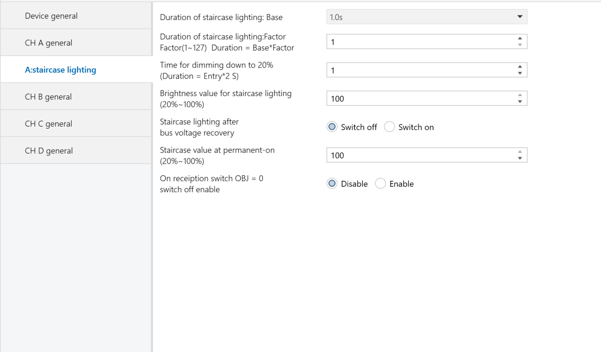 Figure 2-8: CH X staircase lighting setting interface
Duration of staircase lighting : Base
Setting the time of base: 1.0 s / 2.1 s /.../ 1.1 min /.../ 1.2 h
Duration of staircase lighting: Factor
Setting the time of factor: 1~127 s
When the staircase light is turned on using switch mode, the duration it remains on is calculated as: duration = base * factor. After this period, the brightness will gradually decrease to 20% before the light turns off.
Time for dimming down to 20%(Duration=Entry*2)
Set the time for the staircase light to dim to 20% as the input value multiplied by 2 seconds, up to a maximum of 255 seconds. Once the brightness has gradually decreased to 20%, the light will turn off.
Brightness value for staircase lighting(20%~100%)
Set the brightness value for the staircase light in switch mode, ranging from 20% to 100%.
Staircase lighting after bus voltage recovery
Determine whether the staircase light should be on or off upon bus power recovery.
Options:
Switch on: Upon bus power recovery, the staircase light turns on with a duration of: duration = base * factor. The dimming time to 20% is set by the parameter “Time for dimming down to 20% (Duration = Entry * 2)” .
Switch off: The staircase light will be in the off state upon bus power recovery.
Staircase value at permanent-on(20%~100%)
Set the staircase light to a fixed brightness. It remains on unless an “off” telegram is received. In “permanent on” mode, the light dims to 20% based on the “Time for dimming down to 20% (Duration = Entry * 2)” parameter before turning off. The brightness can be set from 20% to 100%.
On reception switch OBJ=0 switch off enable
Options:
Enable: Send “off” command by the communication object “switch” no matter in switch or permanent on mode.
Disable: In the permanent on mode, only the “off” command from the “permanent on” object will stop the output.
Note:
In switch output mode, you can start permanent on mode but cannot stop it unless the permanent on mode was previously activated.
3. Description of communication objects
A communication object enables device interaction on the bus, as only these objects can communicate with the BUS.
Note:
Each communication object serves a specific function, exemplified by a 1-fold universal dimmer.
“C" represents that the communication object's communication function is enabled.
“W" indicates that the value of the communication object can be rewritten via the bus.
“R" signifies that the value of the communication object can be read via the bus.
“T" denotes that the communication object has transmission capability.
“U" means that the value of the communication object can be updated.
3.1 Communication objects of “Device General”
Under “Device General”, there are 2 communication objects, as shown in Figure 3-1.
 Figure 3-1: Device General communication object
Function | Name | Data Type | Flags | |
45 | In operate | In operate | 1bit | C,T |
This communication object periodically sends telegrams of “1” or “0” to the bus to indicate the device's operational status. It is enabled when the “Send object 'in operation'” parameter is set to either “send value '0' cyclically” or “send value '1' cyclically”. If set to “send value '0' cyclically”, it sends the telegram “0”; if set to “send value '1' cyclically”, it sends the telegram “1”. If the option is set to “no,” the object is disabled. | ||||
44 | Report error of device | Error report | 1byte | C,R,T |
This communication object is used to report system error states. It is only enabled when the parameter “Error report" is set to “Enable". When enabled, it reports errors such as overheat, overload, and short circuit, and may trigger alarms or automatically shut down the device. If set to “Disable", the communication object is disabled. Assuming an 8-bit command (telegram code) as: 76543210
| ||||
3.2 General communication objects of “Dimming Actuator”
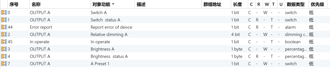 Figure 3-2: Each channel communication object
No. | Function | Name | Data Type | Flags |
1 | Switch status X | OUTPUT X | 1bit | C,R, T |
This communication object is used to report the current switch status to the bus. When the brightness value is greater than 0, this communication object sends “1" to the bus; when the current brightness value is 0, it sends “0" to the bus. This communication object is enabled when the parameter "Status report" is set to “It's new status." | ||||
0 | Switch X | OUTPUT X | 1bit | W,C |
This communication object is used only to switch the dimmer on or off. The device receives switch commands through this communication object. If it receives a telegram with the logical value "1," the dimmer is turned on; if it receives "0," the dimmer is turned off. | ||||
4 | Brightness status X | OUTPUT X | 1byte | C,R,T |
This communication object is used to report the current channel output brightness to the bus. Regardless of the reason for the brightness change, the communication object sends data to the bus, reporting the current brightness value. This communication object is enabled when the parameter “Brightness value OBJ transmit after dimming" is set to “Transmit new brightness." | ||||
3 | Brightness X | OUTPUT X | 1byte | W,C |
This communication object is used to turn the dimmer on or off by receiving a brightness value. If the received brightness value is greater than 0, the dimmer is turned on. If the received brightness value is “0”, the dimmer may either turn off or maintain the brightness at the low threshold value, depending on the settings in the brightness dimming parameters. | ||||
2 | Relative dimming X | OUTPUT X | 4bit | C,W |
This communication object controls dimming up or down. When the input value is 1 to 7, it dims down, with larger values resulting in smaller dimming increments (1 for maximum dimming and 7 for minimum). A value of 0 stops the dimming down function. When the input value is 9 to 15, it dims up, with larger values resulting in smaller dimming increments (9 for maximum dimming and 15 for minimum). A value of 8 stops the dimming up function. | ||||
3.3 Communication objects of scene function
 Figure 3-3: Scene function communication object
No. | Function | Name | Data Type | Flags |
6 | Scene /save X | OUTPUT X | 1Byte | W,C |
This object is used to call or store a scene using an 8-bit command. It is only enabled when the scene function is activated. The 8-bit command is defined as follows: Assuming an 8-bit command as (binary code): FXNNNNNN
| ||||
3.4 Communication objects of preset function
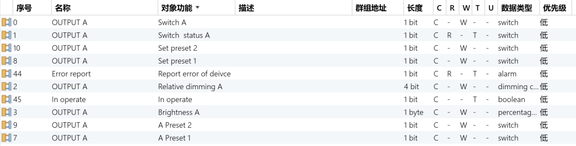 Figure 3.4: Preset function communication object
No. | Function | Name | Data Type | Flags |
7 | X preset 1 | OUTPUT X | 1bit | W,C |
This object is for Preset 1. Through this communication object, you can call the preset values. When a telegram with the logical value “0" is received, the brightness of the dimmer is determined by the parameter “brightness value at obj=0". When a telegram with the logical value "1" is received, the brightness is determined by the parameter “brightness value at obj=1". This communication object is enabled only after Preset 1 is activated. | ||||
8 | Set preset 1 | OUTPUT X | 1bit | W,C |
This object is used to modify the brightness value of Preset 1. It is enabled only when the parameter “Preset 1 can be set via the bus” is set to “Enable.” Through this communication object, you can save the current brightness state as a new preset value. A logical value of “0” saves the current brightness state to the parameter “brightness value at obj=0,” replacing the existing value. A logical value of “1” saves the current brightness state to the parameter “brightness value at obj=1,” replacing the existing value. | ||||
9 | X preset 2 | OUTPUT X | 1bit | W,C |
This object is for Preset 2. Through this communication object, you can call the preset values. When a telegram with the logical value “0" is received, the brightness of the dimmer is determined by the parameter “brightness value at obj=0.” When a telegram with the logical value “1" is received, the brightness is determined by the parameter “brightness value at obj=1.” This communication object is enabled only after Preset 2 is activated. | ||||
10 | Set preset 2 | OUTPUT X | 1bit | W,C |
This object is used to modify the brightness value of Preset 2. It is enabled only when the parameter “Preset 2 can be set via the bus” is set to “Enable.” Through this communication object, you can save the current brightness state as a new preset value. A logical value of “0” saves the current brightness state to the parameter “brightness value at obj=0,” replacing the existing value. A logical value of “1” saves the current brightness state to the parameter “brightness value at obj=1,” replacing the existing value. | ||||
3.5 Communication objects of staircase lighting function
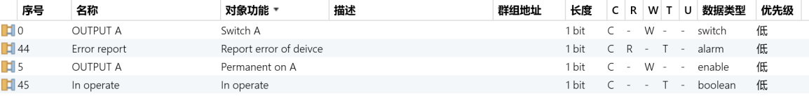 Figure 3-5: Staircase lighting function communication object
No. | Function | Name | Data type | Flags |
0 | Switch X | OUTPUT X | 1bit | W,C |
This object controls the staircase lighting function of the dimmer. When receiving the logical value “1”, the staircase light turns on for a period calculated as duration = base * factor, after which the light automatically turns off. When receiving logical value “0”, turns off the staircase light immediately . | ||||
5 | Permanent on X | OUTPUT X | 1bit | C,W |
When this communication object receives a logical value of “1”, it keeps the staircase light on for a long time. When it receives a logical value of “0”, it turns off the staircase light. | ||||