Device Network Configuration
To ensure normal functioning, make sure that the device has its IP address set correctly or obtained automatically from the DHCP server.
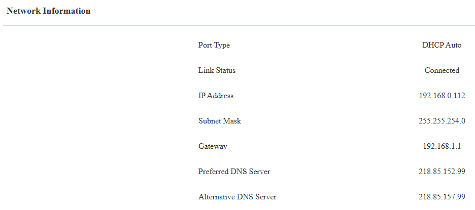
Check the network status on the web Status > Info > Network Information interface.
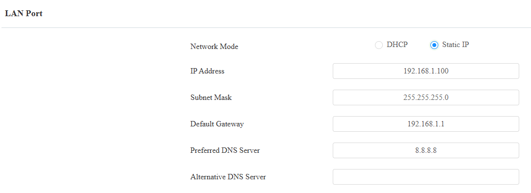
Set the network connection on the web Network > Basic interface.
DHCP: DHCP mode is the default network connection. If the DHCP mode is turned on, the door phone will be assigned by the DHCP server with an IP address, subnet mask, default gateway, and DNS server address automatically.
Static IP: When static IP mode is selected, the IP address, subnet mask, default gateway, and DNS server address(es) have to be manually configured according to the actual network environment.
IP Address: Set up the IP address when the static IP mode is selected. To access the device’s web settings, you computer should be on the same local network as the device.
Subnet Mask: A subnet mask tells your device which IP addresses are part of your local network and which ones are not. For example, if the subnet mask is 255.255.255.0, it means that devices with similar starting IPs (like 192.168.1.x) are in the same network.
Default Gateway: The gateway is like a bridge between your device and other networks, such as the internet. Usually, it’s the IP address of your router.
Preferred/Alternative DNS: Domain Name System(DNS) is the overall system or network that handles the translation of domain names (like www.example.com) into IP addresses (like 192.0.2.1), which computers use to identify each other on a network. The door phone connects to the alternate DNS server when the primary one is unavailable.
Device Deployment in Network
To facilitate device control and management, configure Akuvox intercom devices with details such as location, operation mode, address, and extension numbers.
To set it up, navigate to the web Network > Advanced interface.
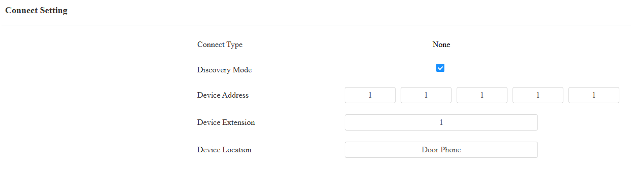
Connect Type: It is automatically set up according to the actual device connection with a specific server in the network, such as SDMC, Cloud, or None.
None: None is the default factory setting, indicating the device is not in any server type. Devices connect directly to each other or within a local area network (LAN) without relying on external servers.
Cloud: The device is connected to the SmartPlus Cloud, a cloud-based system simplifying property access management. The Cloud mode allows devices to interact intelligently with one another and the mobile SmartPlus App, backing up data daily and on different hosts. It suits projects requiring smart, flexible, and secure deployment and management.
SDMC: The device is connected to the SDMC, a management platform designed for on-premise projects. The SDMC mode manages and backs up data remotely on a local network. It also boasts many features suitable for projects requiring high privacy, lower cost, and centralized management.
Discovery Mode: Enabled by default. Available for None server mode. The device can be discovered by other devices in the network. When disabled, the device will be concealed and not be discovered by other devices.
Device Address: Available for None server mode. It can be used to call the device. Specify the device address by entering device location information from left to right: Community, Building, Unit, Floor, and Room in sequence.
Device Extension: Available for None server mode. The device extension number ranges from 0 to 10.
Device Location: The location in which the device is installed and used. Available for None server mode.
Device Local RTP Configuration
Real-time Transport Protocol(RTP) lets devices stream audio and video data over a network in real time.
To use RTP, devices need a range of ports. A port is like a channel for data on a network. By setting up RTP ports on your device and router, you can avoid network interference and improve audio and video quality.
To configure RTP, navigate to the web Network > Advanced interface.
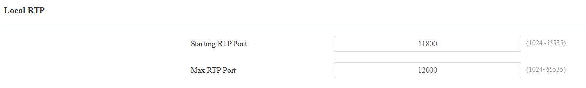
Starting RTP Port: The port value for establishing the start point for the exclusive data transmission range.
Max RTP Port: The port value for establishing the endpoint for the exclusive data transmission range.
SNMP Setting
Simple Network Management Protocol(SNMP) is a protocol for managing IP network devices. It allows network administrators to monitor devices and receive alerts for attention-worthy conditions. SNMP provides variables describing system configuration, organized in hierarchies and described by Management Information Bases (MIBs).
To configure SNMP, navigate to the web Network > Advanced interface.
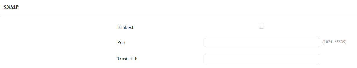
Port: The SNMP server’s port.
Trusted IP: The allowed SNMP server address. It can be an IP address or any valid URL domain name.
VLAN Setting
A Virtual Local Area Network (VLAN) is a logical group of nodes from the same IP domain, regardless of their physical network segment. It separates the layer 2 broadcast domain via switches or routers, sending tagged packets only to ports with matching VLAN IDs. Utilizing VLANs enhances security by limiting ARP attacks to specific hosts and improves network performance by minimizing unnecessary broadcast frames, thereby conserving bandwidth for increased efficiency.
To configure VLAN, navigate to the web Network > Advanced interface.
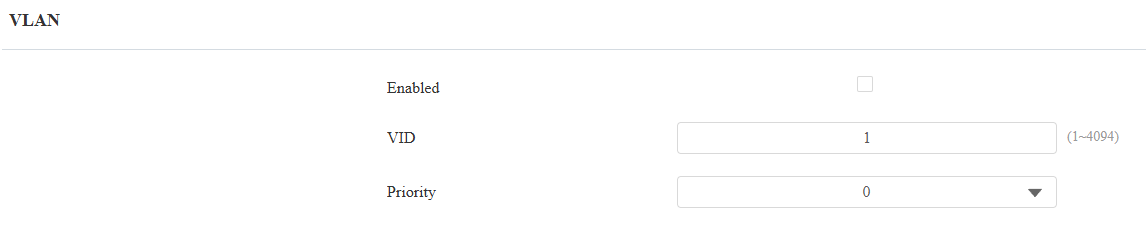
VID: The VLAN ID for the designated port.
Priority: The VLAN priority for the designated port.
QoS Setting
Quality of Service(QoS) is a network's ability to provide better service for specific network communications by utilizing various technologies. It serves as a security mechanism in networks, addressing issues like network latency and congestion. Ensuring QoS is crucial for networks with limited capacity, particularly for multimedia applications such as VoIP and IPTV. These applications often require a consistent transmission rate and are sensitive to delays.
To configure QoS, navigate to the web Network > Advanced interface.
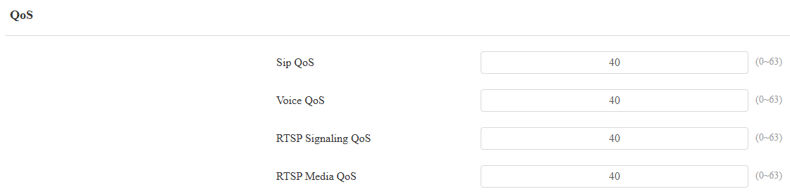
SIP QoS: SIP QoS can be analyzed by registering an account and capturing SIP packets.
Voice QoS: Voice QoS can be analyzed during a call by capturing and examining RTP packets.
RTSP Signaling QoS: RTSP Signaling QoS can be analyzed using VLC and capturing RTP packets.
RTSP Media QoS: RTSP Media QoS can be analyzed by viewing the stream in VLC and capturing RTP packets.
TR069 Setting
TR-069 (Technical Report 069) provides the communication between Customer-Premises Equipment (CPE) and Auto-Configuration Servers (ACS). It includes both a safe auto configuration and the control of other CPE management functions within an integrated framework. For door phones, the administrators can manage all the devices on a common TR-069 Platform. IP phones can be easily and securely configured on the TR-069 platform to make mass deployment more efficient.
To configure it, navigate to the web Network > Advanced interface.
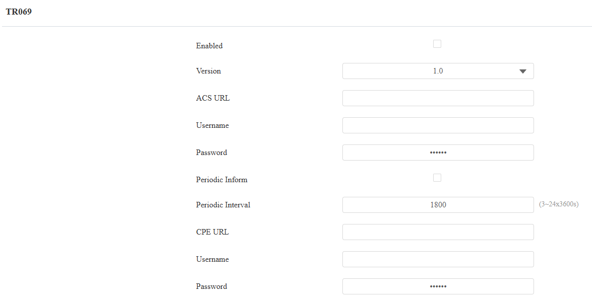
Version: Select the supported TR069 version (version 1.0 or 1.1).
ACS/CPE URL: The URL address for ACS or CPE. ACS is short for auto-configuration servers on the server side, and CPE is short for customer-premise equipment, as the client-side device.
Periodic Interval: The interval for periodic notifications.
Device Web HTTP Setting
This function manages device website access. The device supports two remote access methods: HTTP and HTTPS (encryption).
To configure it, navigate to the web Network > Advanced interface.
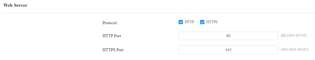
HTTP Port: The port for the HTTP access method. 80 is the default port.
HTTPS Port: The port for the HTTPS access method. 443 is the default port.
NAT Setting
Network Address Translation(NAT) lets devices on a private network use a single public IP address to access the internet or other public networks. NAT saves the limited public IP addresses and hides the internal IP addresses and ports from the outside world.
To register SIP accounts on third-party servers in a Wide Area Network(WAN), you need to enable the RPort feature on the intercom devices to establish a stable connection.
To set up NAT, navigate to the Account > Basic > NAT interface.
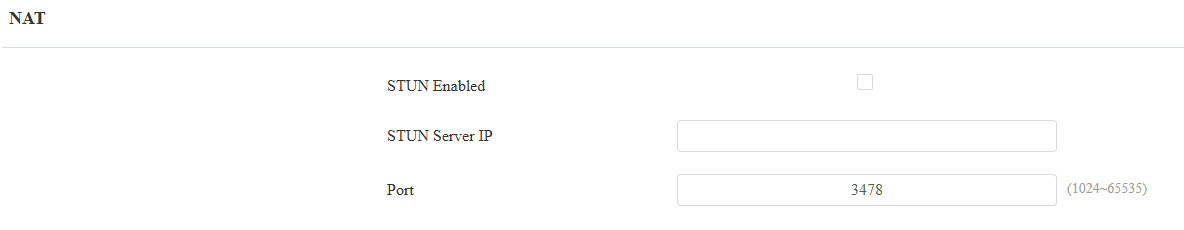
Stun Server IP: Set the SIP server address in the Wide Area Network(WAN).
Port: Set the SIP server port.
Then set up NAT on the Account > Advanced > NAT interface.
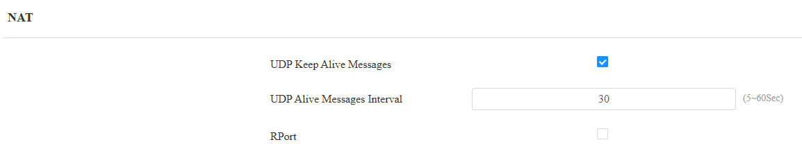
UDP Keep Alive Messages: If enabled, the device will send out the message to the SIP server so that the SIP server will recognize if the device is in online status.
UDP Alive Messages Interval: The message-sending time interval ranges from 5 to 60 seconds. The default is 30 seconds.
RPort: Enable the RPort when the SIP server is in the WAN.
LTE Wireless Connection
The LTE module enables cellular network connectivity for the device in areas where wired networks are unavailable, particularly beneficial for installations in older buildings.
Only the S535 with the LTE module installed displays the settings.
Set this feature up on the Network > Advanced interface.
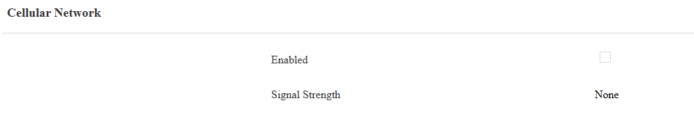
Signal Strength: Indicate the network connection.
None: No SIM card inserted or the SIM card is not properly inserted, unable to detect signal.
Weak: The network signal is poor, typically when the signal strength is below -100 dBm.
Fair: The network signal is average, usually when the signal strength is between -90 and -100 dBm.
Good: The network signal is good, generally when the signal strength is between -70 and -90 dBm.
Excellent: The network signal is excellent, typically when the signal strength is between -50 and -70 dBm.
You can also set up the LTE connection on the Setting > Network screen.
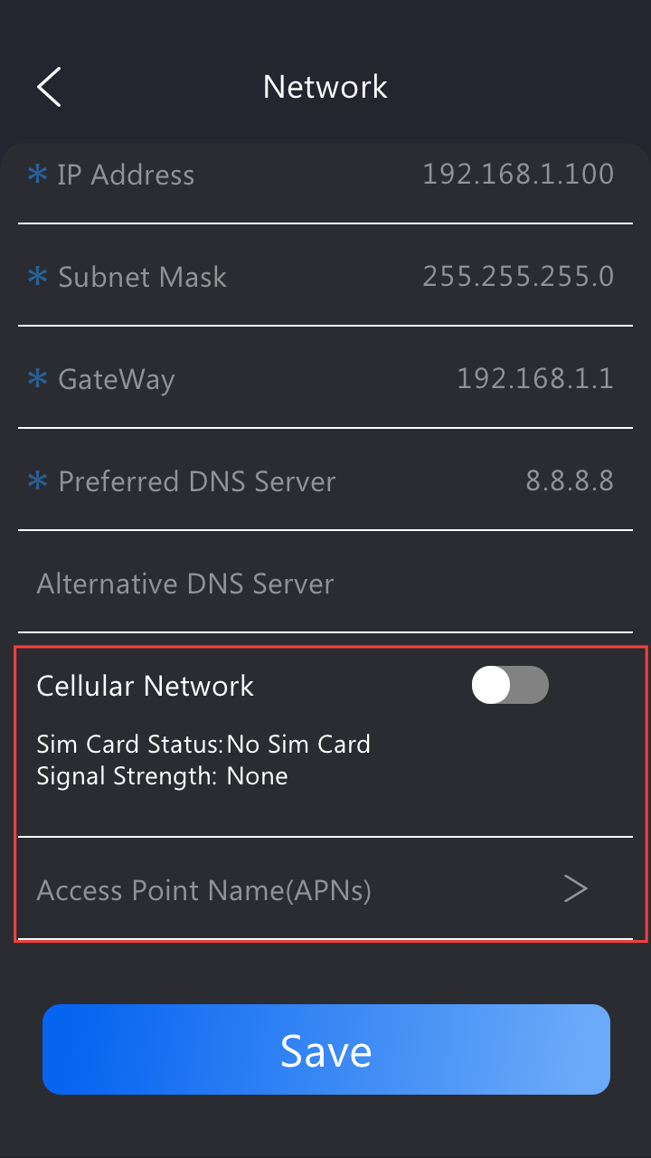
Access Point Name(APNs): You can press this option to add new APNs. Fill in the information from your network provider.