Built-in Relays
The A094 access controller has eight built-in relays in total. Two of the first four relays are on the mainboard, and the other two are on the expanded board. And the rest of the four auxiliary relays(Output A, B, C, D) are on the expanded board. You can connect relays to electrical door locks for door access control.
Set up relays on the web Access Control > Relay interface.
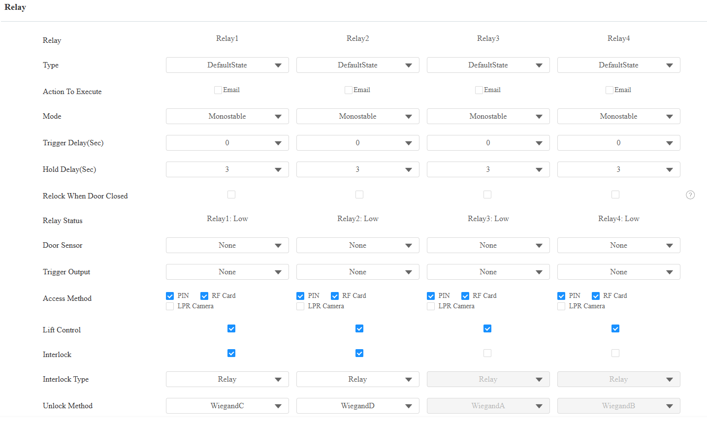
Type: Determine the interpretation of the Relay Status regarding the state of the door:
Default State: A “Low” status in the Relay Status field indicates that the door is closed, while “High” indicates that it is open.
Invert State: A “Low” status in the Relay Status field indicates an open door, while “High” indicates a closed one.
Action to Execute: Send an email notification to the preconfigured email address.
Mode: Specify the conditions for automatically resetting the relay status.
Monostable: The relay status resets automatically within the relay delay time after activation.
Bistable: The relay status resets upon triggering the relay again.
Trigger Delay(Sec): Set the delay time before the relay triggers. For example, if set to 5 seconds, the relay activates 5 seconds after it is triggered.
Hold Delay(Sec): Determine how long the relay stays activated. For example, if set to 5 seconds, the relay remains open for 5 seconds before closing.
Relock When Door Closed: Specify whether the relay should be reset (door relocked) immediately when the door is physically closed.
If disabled(the default), the relay reset follows the configured Hold Delay (Sec). The relay will remain active until the configured time expires, regardless of the door’s magnetic status.
If enabled, the relay is reset immediately when the door magnetic Input detects that the door is closed. The door will be relocked without waiting for the Hold Delay time to expire.
Relay Status: Indicate the states of the relay, which are normally opened and closed. By default, it shows low for normally closed(NC) and high for Normally Open(NO).
Door Sensor: Specify which input interface is connected to a door sensor.
Trigger Output: A094 has four extra relays that can be connected to some devices, such as a smoke sensor, to carry out preset actions like setting off alarms or turning on the light. They can be triggered with specific relays.
Access Method: Check the method(s) to trigger the relay.
Lift Control: Set whether to perform lift control when the specific relay is triggered.
Interlock: This feature limits the opening of other doors when one door is open. For example, enable Interlock for Relays 1, 2, and 4. When Relay 1 is opened, Relay 2 or 4 cannot be opened until Relay 1 is closed. While Relay 3 is not affected.
Interlock Type: Available when Interlock is enabled. Set how to determine the door is closed, by relay reset or input reset.
Unlock Method: Available when Interlock is enabled. Specify the method that opens the relay. The settings of the corresponding Wiegand and Input will be overwritten.
Note
Click here to view the detailed explanation of the Interlock feature.
Set up the extra relays on the web Access Control > Auxiliary Output interface.
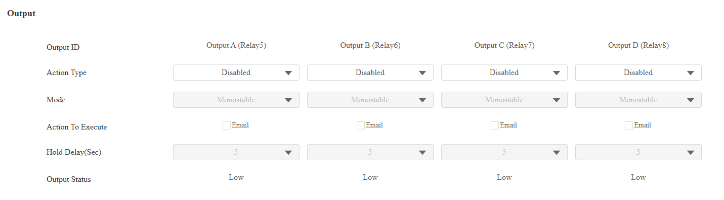
Action Type: Set whether to use the Output. When Open is selected, the Hold Delay option can be configured.
Mode: Specify the conditions for automatically resetting the relay status.
Monostable: The relay status resets automatically within the relay delay time after activation.
Bistable: The relay status resets upon triggering the relay again.
Action to Execute: Send an email notification to the preconfigured email address.
Hold Delay (Sec): Determine how long the relay stays activated. For example, if set to 5 seconds, the relay remains open for 5 seconds before closing.
Output Status: Indicate the states of the relay, which are normally opened and closed. By default, it shows low for normally closed(NC) and high for Normally Open(NO).
Web Relay
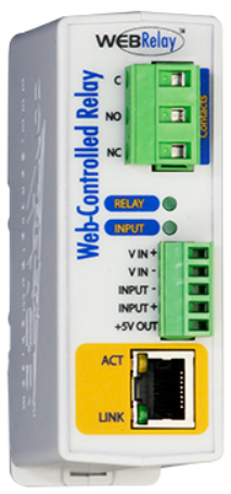
A web relay has a built-in web server and can be controlled via the Internet or a local network. The device can use a web relay to either control a local relay or a remote relay somewhere else on the network.
To set it up, navigate to the Access Control > Web Relay interface.
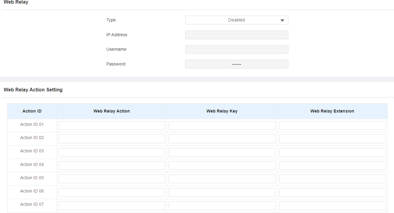
Type: Determine the type of relay activated when employing door access methods for entry.
Disabled: Only activate the local relay.
Web Relay: Only activate the web relay.
Both: Activate both the local relay and web relay. Typically, the local relay is triggered first, followed by the web relay.
IP Address: The web relay IP address provided by the web relay manufacturer.
Username: The user name provided by the web relay manufacturer.
Password: The manufacturer-provided authentication key for the web relay. Authentication occurs via HTTP. Leaving the Password field blank indicates non-use of HTTP authentication. You can define the password using HTTP GET in the Web Relay Action field.
Web Relay Action: Configure the actions to be performed by the web relay upon triggering. Enter the manufacturer-provided URLs for various actions, with up to 50 commands.
Web Relay Key: The configured DTMF code. When the door is unlocked via the DTMF code, the action command will be sent to the web relay automatically.
Note
If the URL includes full HTTP content (e.g., http://admin:admin@192.168.1.2/state.xml?relayState=2), it doesn't rely on the IP address that you entered above. However, if the URL is simpler (e.g., "state.xml?relayState=2"), the relay uses the entered IP address.
Web Relay Key: Determine the methods to activate the web relay based on whether the DTMF code is filled.
- Filling with the configured DTMF code restricts activation to card swiping and DTMF.
- Leaving it blank enables all door-opening methods.
Web Relay Extension: Specify the intercom device and the methods it can use to activate the web relay during calls.
- When an intercom device’s IP/SIP is specified, only that device can trigger the web relay (except for via card swiping or DTMF) during calls.
- If left blank, all devices can trigger the relay during calls.