This interface mainly sets the general parameters of the DALI device in the channel, such as KNX bus failure or reset action, status transmission mode, failure report and failure analysis. The parameters of the two channels are the same as the objects. The following is an example of one of the channels.
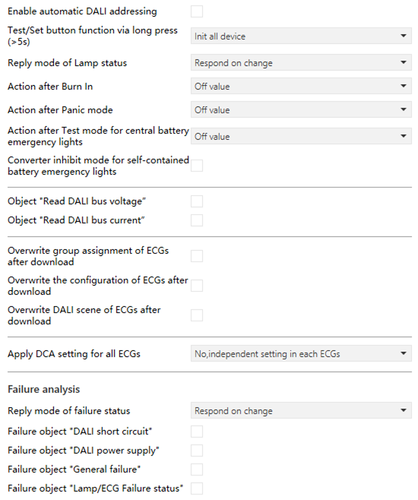

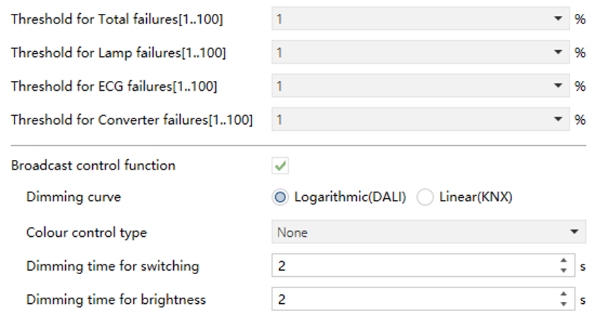
Fig.5.3 “DALI Output A/B” Interface
Parameter “Enable automatic DALI addressing”
This parameter sets whether a DALI device without a DALI address is automatically initialized after the gateway supply voltage recovery or reset, that is, whether the gateway automatically assigns it the first free DALI address.
Disable: The gateway does not assign DALI addresses on gateway supply voltage recovery. If a DALI device without an address has been installed, the gateway can only control it using a broadcast telegram. If a DALI device with an existing address has been installed, the gateway will not change it. (DALI addresses can still be assigned via DCA tool or the gateway’s Test/Set button.)
Enable: If the gateway locates a DALI device without a DALI address after supply voltage recovery, the gateway automatically allocates it the first free DALI address.
DALI addressing without gaps makes it possible to replace a defective DALI device without additional addressing or commissioning. All that is required is to connect a DALI device without address. The gateway addresses the new device with the first free DALI address of the removed failed device, and transfers its properties to the new device.
Parameter “Test/Set button function via long press(>5s)”
This parameter defines the function of the Test/Set button and must be activated by pressing and holding the button for more than 5 seconds.
Options:
No action
Init no address device: The gateway can initialize the DALI devices without a DALI address on the DALI bus via long press the button >5s.
Init all device: The gateway can reinitialize all DALI devices on the DALI bus via long press the button >5s.
Parameter “Reply mode of light status”
This parameter defines the feedback conditions for light status during group or ECG control, including switch status and brightness status.
Options:
Respond after read only: The status object send the current switch or brightness status to the bus. Only when the device receives a request from another bus device or bus to read the switch status or brightness status of the group or ECG.
Respond after change: When the switch status or brightness status changes, the status object sends a telegram to the bus to report the current status.
Respond after change and bus reset: When the switch status, brightness status changes or bus reset, the status object sends a telegram to the bus to report the current status.
NOTE:
The switch and brightness status of a group can only provide a local summary and do not accurately reflect the status of each individual light. It is recommended to use the status feedback of the ECG for precise monitoring.
Parameter “Action after Burn In”
This parameter defines the brightness value of the ECG/light after burnt in.
Options:
On value: Outputs the brightness value of "Switch on".
Off value: The outputs are off.
Last brightness value: The brightness value of the ECG/light will be saved before burnt in. After the burn in is completed, the ECG/light returns to the previous brightness value.
Parameter “Action after panic mode”
This parameter defines the brightness value of the ECG/light after panic mode. Options:
On value: Outputs the brightness value of "Switch on"
Off value: The outputs are off.
Last brightness value: The brightness value of the ECG/light will be saved before panic mode. After the panic mode is completed, the ECG/light returns to the previous brightness value.
NOTE:
This function is only supported in database versions 2.0 or above and DCA versions 2.0.0.1 or above.
Parameter “Action after test mode for central battery emergency lights”
This parameter defines the brightness value of the ECG/light after test mode for central battery emergency lights.
Options:
On value: Outputs the brightness value of "Switch on".
Off value: The outputs are off.
Last brightness value: The brightness value of the ECG/light will be saved before test mode. After the test mode is completed, the ECG/light returns to the previous brightness value.
NOTE:
This function is only supported in database versions 2.0 or above and DCA versions 2.0.0.1 or above.
Parameter “Converter inhibit mode for self-contained battery emergency lights”
This parameter sets whether to enable the function of converter inhibit mode for self-contained battery emergency lights.
If there is a power supply failure, self-contained battery emergency lights always change to emergency mode. The light is now powered by internal battery. However, during commissioning and installation, it may be necessary to cut off the power to prevent continuous emergency lighting and battery discharge.
Enable this parameter to prevent lights from switching to emergency mode. Once enabled, the DALI gateway sends an inhibit telegram via “Converter inhibit mode”. Drivers turn off all emergency lights in channel within 15 minutes after receiving command, does not switch to emergency mode. After power recovery, lights return to normal mode. If there is no power supply failure in 15 minutes, converters reset to normal mode.
NOTE:
This function is only supported in database versions 2.0 or above and DCA versions 2.0.0.1 or above.
Parameter “Object "Read DALI bus voltage”
This parameter sets whether to enable the object for reading the DALI bus voltage, responding only to the DALI bus voltage status when read.
Parameter “Object "Read DALI bus current”
This parameter sets whether to enable the object for reading the DALI bus current, responding only to the DALI bus current status when read.
Parameter “Overwrite group assignment of ECGs after download”
This parameter sets whether to overwrite group assignment of ECGs after download. When enabled, the group assignment saved in the gateway will be sent to all ECGs after download. This function is mainly used when replacing failed ECGs.
NOTE:
This function is only supported in database versions 2.0 or above and DCA versions 2.0.0.1 or above.
Parameter “Overwrite the configuration of ECGs after download”
This parameter determines whether to overwrite ECG configurations after download. When enabled, the configurations saved in the gateway will be sent to all ECGs. This function is primarily used when replacing failed ECGs.
When enabled, note:

NOTE:
This function is only supported in database versions 2.0 or above and DCA versions 2.0.0.1 or above.
Parameter “Overwrite DALI scene of ECGs after download”
This parameter determines whether to overwrite DALI scene of ECGs after download. When enabled, the DALI scenes saved in the gateway will be sent to all ECGs after download. This function is primarily used when replacing failed ECGs.
NOTE:
This function is only supported in database versions 2.0 or above and DCA versions 2.0.0.1 or above.
NOTE:
If any of the above three parameters are enabled, note:

Parameter “Apply DCA setting for all ECGs”
This parameter determines whether the DCA settings are applied to all ECGs.
Options:
No, ETS parameter setting to all ECGs: DCA settings are not applied to ECGs; the “Apply DCA setting for ECG” parameter in each ECG is read-only and disabled.
No, independent setting in each ECGs: DCA settings are not applied globally; the “Apply DCA setting for ECG” parameter must be configured individually for each ECG.
Yes: DCA settings are applied to all ECGs; the “Apply DCA setting for ECG” parameter in each ECG is read-only and disabled.
NOTE:
This function is only suitable for versions with database versions of 2.0 or above.
Failure Analysis
Parameter “Reply mode of failure status”
This parameter defines the conditions for sending ECG and light failure conditions. Options:
Respond after read only: The status object sends the current failure status to the bus only when another bus device or ECG/group requests it.
Respond after change: The status object automatically sends a telegram to the bus whenever the failure status changes.
Respond after change and bus reset: The status object sends a telegram to the bus whenever the failure status changes or after a bus reset.
Parameter “Failure object ‘DALI short circuit’”
This parameter is used to report whether a short circuit is present on the connected DALI bus.
Parameter “Failure object "DALI power supply"”
This parameter is used to report whether there is an failure in the power supply of the DALI bus.
Parameter “Failure object ‘General failure’”
This parameter reports faults on the DALI bus channel. When a fault occurs (e.g., ECG or lamp fault), the object sends a telegram with value "1" on the bus. When the fault is cleared, it sends "0".
Parameter “Failure object ‘light/ECG Failure status’”
This parameter sets whether the channel ECG/light failure status object is enabled for centralized sending.
Enable: The object “Light/ECG Failure Status” becomes active and is used to report the status of lights or ECGs. The 1-byte object value is defined as follows:
Bit 7 | Bit 6 | Bit 5 | Bit 4 | Bit 3 | Bit 2 | Bit 1 | Bit 0 |
ECG failure | light failure | ECG number1..64 | |||||
Example:
This object can also be used to query the light and ECG failure. When the highest two bit value, both Bit7 and Bit6, of the telegram received by the object are 1, indicating to query the ECG x failure, such as:
| |||||||
TIP:
Light failure: One or more fixtures are not working (damaged) or not connected.
ECG failure: One or more ballasts on the DALI gateway output are not working or not connected.
Parameter “Function of failure object”
This parameter sets the transmission mode of the light and ECG failure - either as the total number of faulty devices or as a failure rate. The data type of failure objects 7, 9, and 11 varies depending on the selected mode.
Options:
Total number of failures: Send the number of failed devices on the bus whenever the failure status changes
Failure rate 0..100%: Send the percentage of faulty devices relative to the total number of devices on the bus. For example, if there are 8 lights and 1 fails, the light failure rate is 12%.
Parameter “Threshold for Total failures[1...100]”
This parameter is used to configure the alarm threshold for all (ECG and light) failures (object 8) in the channel. The threshold relates to the failure of all ECGs and lights at the DALI end of the channel, and when the total number of failures exceeds the set threshold, the object 8 sends an alarm.
Options: 1..100%
Parameter “Threshold for light failures[1...100]”
This parameter is used to configure the alarm threshold for all light failures (object 10) of the channel. The threshold relates to the failure of all the lights at the DALI end of the channel, and when the total number of failures exceeds the set threshold, the object 10 sends an alarm.
Options: 1..100%
Parameter “Threshold for ECG failures[1...100]”
This parameter is used to configure the alarm threshold for all ECG failures (object 12) of the channel. The threshold relates to the failure of all ECGs at the DALI end of the channel, and when the total number of failures exceeds the set threshold, the object 12 sends an alarm.
Options: 1..100%
Parameter “Threshold for converter failures[1...100]”
This parameter is used to configure the alarm threshold for all converter failures (object 17) of the channel. The threshold relates to the failure of all converts at the DALI end of the channel, and when the total number of failures exceeds the set threshold, the object 17 sends an alarm.
Options: 1..100%
NOTE:
This function is only supported in database versions 2.0 or above and DCA versions 2.0.0.1 or above.
Parameter “Broadcast control function”
This parameter sets whether to enable the broadcast control function.
Broadcast control applies to all devices on that channel, allowing them to receive DALI broadcast control even if they are not individually addressed.
When the broadcast control function is enabled, the following parameters are visible:
❖ Parameter “Dimming curve ”
This parameter defines the dimming curve for broadcast control.
Options:
Logarithmic(DALI)
Linear(KNX)
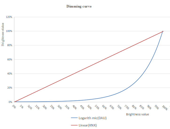
By default, the KNX-to-DALI control uses a logarithmic dimming curve for all ballasts. A linear dimming curve is also available, achieved via the gateway’s internal adjustment process to produce a linear dimming effect.
The logarithmic(DALI) and linear(KNX) dimming curves as shown in the figure below:
NOTE:
In KNX-to-DALI operation, the ballast curve is set to a logarithmic dimming curve by default. Unless necessary, do not modify the dimming curve. Changing this setting may cause inconsistencies with the existing dimming behavior.
❖ Parameter “Colour control type”
This parameter sets the type of broadcast colour control. Only devices supporting the selected control type will respond.
Options:
None
colour Temperature: Cool-warm colour control.
RGB colour: Three RGB colour control.
RGBW colour: Four RGBW colour control.
XY colour: Control using two coordinates in the colour space.
- Parameter “Object type for RGB colour”
This parameter is visible when “RGB colour” is selected and defines the object type used for RGB colour control.
Options:
RGB(Combined object)
HSV(Separated objects): Represent the hue, saturation, brightness (brightness value adjustment) respectively.
- Parameter “Object type for RGBW colour”
This parameter is visible when “RGBW colour” is selected and defines the object type for RGBW colour control.
Options:
RGBW(Combined object)
HSVW(Separated objects)
- Parameter “Object type for XY colour”
This parameter is visible when “XY colour” is selected, and defines the object type for XY colour control.
Options:
XY(Combined object)
XY(Separated objects)
NOTE:
When the broadcast control switch is turned on, the device restores the colour value from before the last switch-off.
Broadcast control "switch on" defaults to 100% brightness when turned on and 0% when turned off.
If a connected ECG is in a special mode (e.g., burn-in mode), it cannot be controlled via broadcast “Switch” or “Brightness dimming” objects, but colour adjustment remains possible.
❖ Parameter “Dimming time for switching”
This parameter defines the dimming time for switch status changes during broadcasting.
Options: 0...255s
❖ Parameter “Dimming time for brightness”
This parameter defines the total dimming time for brightness during broadcast control.
Options: 0...255s