The Humidity sensor parameter interface (Figure 5.6.1) is used to configure humidity-related functions.
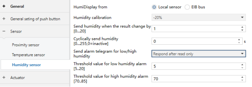
Figure 5.6.1 “Humidity sensor” Interface
HumiDisplay from
Defines the source of the displayed and measured humidity value.
Options:
Local sensor
EIB bus
Humidity calibration
Sets the humidity offset value.
Actual output humidity = measured humidity + calibration value.
If the calculated value exceeds the maximum allowed range, the maximum value is output.
Options:
-20%
-15%
-10%
-5%
-3%
-1%
0%
…
15%
20%
Send humidity when the result change by [0…20]
Defines the humidity change threshold for sending the current humidity value to the bus. If set to 0, this function is disabled.
Options: 0…20
Cyclically send humidity [0…255, 0=inactive]
Defines the cyclic transmission interval of the humidity value to the bus. If set to 0, cyclic transmission is disabled.
Options: 0…255
Send alarm telegram for low/high humidity
Defines how humidity alarm telegrams are handled.
Options:
No respond
Respond after read only: Alarm status is displayed only after a read request from the bus.
Respond after change: Alarm telegram is automatically sent when the threshold is triggered.
Threshold value for low humidity alarm [5…20]
Sets the low-humidity alarm threshold.
Options: 5…20 (%)
Threshold value for high humidity alarm [70…85]
Sets the high-humidity alarm threshold.
Options: 70…85 (%)