The Switch Actuator parameter page is shown in Figure 5.7.1.
The switch actuator provides four output channels. All channels have identical parameters and communication objects. The following description uses one channel as an example.
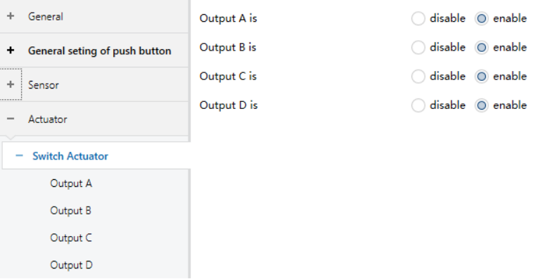
Figure 5.7.1 “Switch Actuator" Interface
Output X is
Enable or disable the actuator control channel.
Options:
disable
enable
The following parameter interface becomes visible when “Output X is" is set to “enable”.
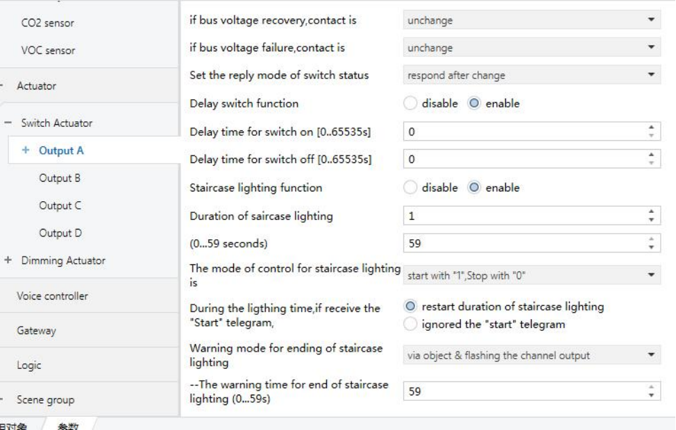
Figure 5.7.2 “Output X" Interface
❖ If bus voltage recovery, contact is
Defines the relay contact state after bus voltage recovery.
Options:
Unchange: Contact remains unchanged.
Open: Contact opens.
Close: Contact closes.
As before bus voltage fail: Contact returns to the state before power failure.
❖ If bus voltage failure, contact is
Defines the relay contact state when bus voltage fails.
Options:
unchange
open
close
❖ Set the reply mode of switch status
Defines how the actuator reports its status to the bus.
Options:
Respond only read request: The object “Switch, Status X” sends the current status to the bus only when a read request is received.
Respond after change: The object “Switch, Status X” immediately sends the current status to the bus after a state change.
Respond always: The object “Switch, Status X” sends the current channel status to the bus every time the relay is triggered.
❖ Delay switch function
Activates the delay switch function.
Options:
Disable
Enable
The following parameters are visible when the “Delay switch function” is “Enabled”.
◇ Delay time for switch on [0...65535s]
Defines the delay time before switching ON.
Options: 0…65535
◇ Delay time for switch off [0...65535s]
Defines the delay time before switching OFF.
Options: 0…65535
❖ Staircase lighting function
Activates the staircase lighting function.
Options:
Disable
Enable
TIP:
Staircase lighting is activated via the communication object “Output of staircase lighting”, whose value is programmable.
When staircase lighting starts, the timing begins immediately. If no warning is configured, the light turns off directly after the configured duration expires.
❖ Duration of staircase lighting — (0…1000 minutes)
Sets the staircase lighting duration (minutes).
Options: 0…1000
❖ Duration of staircase lighting — (0…59 seconds)
Sets the staircase lighting duration (seconds).
Options: 0…59
❖ The mode of control for Staircase lighting is
Defines how staircase lighting is started and stopped.
Options:
Start with "1", stop with "0": The staircase light turns on when the object “Output of staircase lighting” receives logic "1", stops timing when logic "0" is received, maintaining the current contact state until another operation changes it.
Start with "1", no action with "0": The light turns on when receiving logic "1" but ignores logic "0".
Start with "0/1", cannot be stopped: The light turns on for either logic "0" or "1" and cannot be stopped via the communication object.
❖ During the lighting time, if receive the start telegram
Options:
Restart duration of staircase lighting: The staircase light will be turned on again and the timing restarted when a telegram from the communication object “Output of staircase lighting” is received during the staircase lighting period.
Ignore the "switch on" telegram: Telegrams from the communication object “Output of staircase lighting” will be ignored during the staircase lighting period.
❖ Warning mode for ending of staircase lighting
Defines the warning method before the lighting period ends. Users can be notified that the staircase lighting is about to end before the lighting period expires. The warning time is not included in the lighting duration.
If “Nothing” is selected, no warning will be issued. If the staircase lighting is switched off before the warning time, no warning will be triggered.
Options:
Nothing
Via object
Flashing the channel output with OFF/ON
Via object & flashing the channel output
TIP:
Two types of warnings are provided:
Warning via communication object: When the warning starts, the communication object “Warning of staircase” is set to “1” and sent to the bus.
Warning via light flashing: The output is controlled to flash (brief ON/OFF), with a 1-second interval between switches.
These two methods can be used independently or together.
Selecting “via object” enables warning via the communication object.
Selecting “flashing the channel output with OFF/ON” enables warning via light flashing.
Selecting “via object & flashing the channel output” enables both warning methods simultaneously.
The following parameter is visible after a warning mode is selected.
◇ The warning time for ending of staircase lighting (0…59 s)
Sets the warning duration in seconds.
Options: 0…59
❖ Modify the duration via object
Enables modification of the staircase duration via the 2-byte object “Duration of staircase”.
Options:
Disable
Enable
❖ Scene function
Enables or disables the scene function for the channel.
Options:
Disable
Enable
When the Scene function is enabled, the following parameter setting interface becomes visible.

Figure 5.7.3 "X: Scene" Interface
◇ 1…8 <channel is assigned to (1…64 scene NO., 0=no allocation)
Each output channel supports up to 8 scene assignments, selected from 64 scene numbers. If set to 0, the scene assignment is disabled.
Options: 1…64, 0=no allocation
NOTE:
Valid scene numbers 1–64 correspond to telegram values 0–63.
◇ Standard output value is
Defines the relay action when a scene is recalled. The actions are normally open (NO) or normally closed (NC) for this channel.
Options:
OFF
ON
◇ Delay time for scene [0…255 s]
Defines the delay between receiving the scene telegram and executing the relay action.
Options: 0…255