The communication object is the medium through which the device communicates with other devices on the bus, that is, only the communication object can execute bus communication. The role of each communication object is described in detail below.
NOTE:
In the following column of the table attribute, "C" means to enable the communication function of the communication object, "W" means that the communication object value can be rewritten by the bus, "R" means that the communication object value can be read by the bus, "T" means that the communication object has a transmission function, "U" means that the communication object value can be updated.
In DALI control, a group address cannot connect too many communication objects, because the DALI protocol baud rate is only 1.2k, relatively low, allowing up to 7 communication objects to be connected to a group address, otherwise the control may be abnormal, such as it takes a few seconds for the control to complete.
6.1 General Communication Object

Fig.6.1 “General” Communication Object
NO. | Name | Object Function | Type | Attribute | DPT |
1 | General | In operation | 1bit | C,R,T | 1.001 switch |
This communication object is used to periodically send a telegram "1" to the bus to indicate that the device is functioning properly. This communication object is always enabled. | |||||
Table 6.1 “General” Communication Object
6.2 Channel General Communication Object
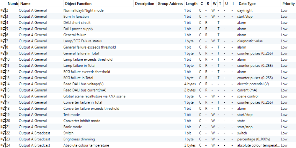



Fig.6.2 “X: General” Communication Object
NO. | Name | Object Function | Type | Attribute | DPT | ||||||||||||||||||
2 | Output X - General | Normal(day)/Night mode | 1bit | C,W | 1.024 day/night | ||||||||||||||||||
This communication object is used to enable or disable night mode via the bus.The object value is defined by the parameter "Normal (day)/Night mode". | |||||||||||||||||||||||
3 | Output X - General | Burn In function | 1bit | C,W | 1.010 start/stop | ||||||||||||||||||
This communication object is used to enable or disable automatic burn in of the group. During the burn in process, all other switch, dimming or brightness value setting telegrams are ignored and the light is all on. Burn in is usually done automatically after the configured burn in time. If the burn in is stopped by this object, the burn in will also stop timing, and the burn in will need to be restarted by this object, and the timing will start again. | |||||||||||||||||||||||
4 | Output X - General | DALI short circuit | 1bit | C,R,T | 1.005 alarm | ||||||||||||||||||
This communication object is used to report whether there is a short circuit in the connected DALI bus. Telegram:
| |||||||||||||||||||||||
5 | Output X - General | DALI power supply | 1byte | C,R,T | 1.005 alarm | ||||||||||||||||||
The communication object is visible when “Failure object DALI power supply" is enable. It reports abnormality of DALI power supply. Telegram:
| |||||||||||||||||||||||
6 | Output X - General | General failure | 1bit | C,R,T | 1.005 alarm | ||||||||||||||||||
This communication object is used to report failures on the DALI bus. When any type of failure occurs, the object will send a telegram "1" to the bus, and the failure will be cleared to "0". | |||||||||||||||||||||||
7 | Output X - General | light/ECG Failure status | 1byte | C,W,T | 238.600 DALI Diagnostics | ||||||||||||||||||
The communication object is visible when “Central failure object "light/ECG Failure status" is enable. Used to send the light or ECG failure status. The bits of the 1byte object are defined as follows:
Example:
This object can also be used to query the light and ECG failure. When the highest two bit value, both Bit7 and Bit6, of the telegram received by the object are 1, indicating to query the ECG x failure, such as:
| |||||||||||||||||||||||
8 | Output X - General | General failure exceeds threshold | 1bit | C,R,T | 1.005 alarm | ||||||||||||||||||
This communication object is used to report that the total number of all lights and ECG failures exceeds the set threshold. | |||||||||||||||||||||||
9 | Output X - General | General failure in Total | 1byte | C,R,T | 5.010 counter pulses | ||||||||||||||||||
This communication object is used to report the total number of all lights and ECG failures.
| |||||||||||||||||||||||
9 | Output X - General | General failure in % | 1byte | C,R,T | 5.001 percentage(0..100%) | ||||||||||||||||||
This communication object is used to report the failure rate, which is the percentage of the total number of devices on the DALI bus. All lights and ECGs are taken into account.
| |||||||||||||||||||||||
10 | Output X - General | light failure exceeds threshold | 1bit | C,R,T | 1.005 alarm | ||||||||||||||||||
This communication object is used to report that the total number of all light failures identified by the gateway exceeds the set threshold. | |||||||||||||||||||||||
11 | Output X - General | light failure in Total | 1byte | C,R,T | 5.010 counter pulses | ||||||||||||||||||
This communication object is used to report the total number of all light failures identified by the gateway. | |||||||||||||||||||||||
11 | Output X - General | light failure in % | 1byte | C,R,T | 5.001 percentage (0..100%) | ||||||||||||||||||
This communication object is used to report the failure rate, which is the percentage of faulty lights in all lights on the DALI bus. | |||||||||||||||||||||||
12 | Output X - General | ECG failure exceeds threshold | 1bit | C,R,T | 1.005 alarm | ||||||||||||||||||
This communication object is used to report that the total number of all ECG failures identified by the gateway exceeds the set threshold. | |||||||||||||||||||||||
13 | Output X - General | ECG failure in Total | 1byte | C,R,T | 5.010 counter pulses | ||||||||||||||||||
This communication object is used to report the total number of all ECG failures identified by the gateway. | |||||||||||||||||||||||
13 | Output X - General | ECG failure in % | 1byte | C,R,T | 5.001 percentage (0..100%) | ||||||||||||||||||
This communication object is used to report the failure rate, i.e the percentage of the faulty ECG to the total number of ECGs on the DALI bus. | |||||||||||||||||||||||
14 | Output X - General | Read DALI bus voltage(V) | 4byte | C,R | 14.027 electric potential(V) | ||||||||||||||||||
The communication object is visible when "Read DALI bus voltage”is enable. Used to read the DALI bus voltage. | |||||||||||||||||||||||
15 | Output X - General | Read DALI bus current (mA) | 2byte | C,R | 7.012 current(mA) | ||||||||||||||||||
The communication object is visible when "Read DALI bus current”is enable. Used to read the DALI bus current. | |||||||||||||||||||||||
16 | Output X - General | Global scene recall/store via KNX scene | 1byte | C,W | 18.001 scene control | ||||||||||||||||||
This communication object is used to recall or store a global scene. Up to 16 scenes are available for the DALI gateway. The KNX scene number assignment, and allow to add ECGs or groups to the scene and set the target brightness, colour temperature and colour for each ECGs or groups. There are 64 scene numbers available. The KNX scene number is defined as follows: Set an 8bit instruction as (binary code): FXNNNNNN
The options are KNX Scene No.1~64. In fact, the scene telegram received by the communication object corresponds to 0~63.
For example, setting KNX Scene No.1, the scene telegram received by the communication object should be 0. | |||||||||||||||||||||||
17 | Output X General | Converter failure in Total | 1byte | C,R,T | 5.010 counter pulses | ||||||||||||||||||
This communication object is used to report the total number of all converter failures identified by the gateway. | |||||||||||||||||||||||
17 | Output X General | Converter failure in % | 1bit | C,R,T | 5.001 percentage (0..100%) | ||||||||||||||||||
This communication object is used to report the failure rate, which is the percentage of faulty lights in all converters of the DALI bus. | |||||||||||||||||||||||
18 | Output X General | Converter failure exceeds threshold | 1bit | C,W | 1.005 alarm | ||||||||||||||||||
This communication object is used to report that the total number of all converter failures identified by the gateway exceeds the set threshold. | |||||||||||||||||||||||
19 | Output X General | Test mode | 1bit | C,W | 1.010 start/stop | ||||||||||||||||||
This communication object is used to activate/stop test mode for central battery emergency lights. Telegrams:
After the setting duration time, the test can also be automatically stopped (set independently in the each ECG). | |||||||||||||||||||||||
20 | Output X General | Converter inhibit mode | 1bit | C,W | 1.011 state | ||||||||||||||||||
This communication object is used to active/inactive inhibit mode for self-contained battery lights. Telegrams:
When it is active, emergency light will not change to emergency mode when power supply failure. When it is inactive, emergency light is in normal mode, and will change to emergency mode when power supply failure. | |||||||||||||||||||||||
21 | Output X General | Panic mode | 1bit | C,W | 1.010 start/stop | ||||||||||||||||||
This communication object is used to activate/stop panic mode for all ECGs and lights. Telegrams:
| |||||||||||||||||||||||
22 | Output X - Broadcast | Switch | 1bit | C,W | 1.001 switch | ||||||||||||||||||
The communication object is visible when “Broadcast control function”is enable. Used for broadcast control and can turn all connected lights on the channel on or off. All ECGs can be switched at the same time, and the brightness value of the on is 100%, and the brightness value of the off is 0%. Telegram:
If the ECG works in the permanent mode, after the broadcast control is turned on, if the ECG brightness read by the gateway from the DALI bus does not match the brightness of the permanent mode, the brightness will become the brightness of the normal mode again. | |||||||||||||||||||||||
23 | Output X - Broadcast | Brightness dimming | 1byte | C,W | 5.001 percentage (0..100%) | ||||||||||||||||||
This communication object is used for broadcast control to set a specific brightness value for all connected lights on the channel. Telegram: 0…100% | |||||||||||||||||||||||
24 | Output X - Broadcast | Absolute colour temperature | 2byte | C,W | 7.600 absolute colour temperature | ||||||||||||||||||
This communication object is visible when "colour Temperature" is selected for the colour control type. It is used for broadcasting colour control. | |||||||||||||||||||||||
24 | Output X - Broadcast | RGB colour value RGBW colour value HSV Hue(H) value | 3byte 6byte 1byte | C,W | 232.600 RGB value 3x (0..255) 251.600 RGBW value 4x (0...100%) 5.003 angle(degrees) | ||||||||||||||||||
24 | Output X - Broadcast | Colour XY value Colour X value | 6byte 2byte | C,W | 242.600 colour xyY 7.001 pulses | ||||||||||||||||||
25 | Output X - Broadcast | Colour Y value | 2byte | C,W | 7.001 pulses | ||||||||||||||||||
25 | Output X - Broadcast | HSV Saturation(S) value | 1byte | C,W | 5.001 percentage | ||||||||||||||||||
26 | Output X - Broadcast | White colour value | 1byte | C,W | 5.001 percentage | ||||||||||||||||||
Displays objects according to the colour control type. Used for broadcasting colour control.
| |||||||||||||||||||||||
1851 | Output X - General | ECGs scene recall/store via DALI scene | 1byte | C,W | 18.001 scene control | ||||||||||||||||||
This communication object is used to recall/store DALI scene via KNX bus, up to 16 scenes are available for ECGs . The scene number assignment are configured in the DCA, there are 16 scene numbers available. Telegram is defined as follows: Set an 8bit instruction as (binary code): FXNNNNNN
The options are Scene 1st~16th. In fact, the scene telegram received by the communication object corresponds to 0~15.
For example, setting Scene 1st, the scene telegram received by the communication object should be 0. | |||||||||||||||||||||||
Table 6.2 “X: General”Communication Object
6.3 Channel Communication Object of a Single Group
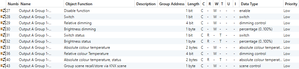
There are 16 groups in the channel. The communication objects of each group are the same and independent of each other. Let's take one of them as an example:
Colour Temperature

RGB(Combined object)


RGB(Separated objects)

RGBW(Combined object)


RGBW(Separated objects)

XY(Combined object)

XY(Separated objects)
Fig.6.3 “X: Group”Communication Object
NO. | Name | Object Function | Type | Attribute | DPT | ||||||||||||||||||||||||||||||||||||||
27 | Output X Group y-{{...}} | Disable function | 1bit | C,W | 1.003 enable | ||||||||||||||||||||||||||||||||||||||
The communication object is visible when “Disable function” is enable. Used to disable/enable control of ECGs in group, the trigger value is defined by the parameter, the device reboot is enabled by default. The name in parentheses changes with the parameter “Description (max 30char.)”. If description is empty, display “Output X Group y-...” by default. The same below. | |||||||||||||||||||||||||||||||||||||||||||
28 | Output X Group y-{{...}} | Switch | 1bit | C,W | 1.001 DPT_Switch | ||||||||||||||||||||||||||||||||||||||
This communication object is used to switch on or off the ECGs in group, y=1..16. The value for "Switch on" can be defined by a parameter template. See section 5.4.1 for details. | |||||||||||||||||||||||||||||||||||||||||||
29 | Output X Group y-{{...}} | Relative dimming | 4bit | C,W | 3.007 dimming control | ||||||||||||||||||||||||||||||||||||||
This communication object is used for relative dimming of the ECGs in group. The highest bit Bit4 decides to brighten or darken, Bit 0..3 determines the dimming size, and Bit 0..3 is 0 to stop dimming. The correspondence between the value of the relatively dimming telegram and brightness chance is as follows:
| |||||||||||||||||||||||||||||||||||||||||||
30 | Output X Group y-{{...}} | Brightness dimming | 1byte | C,W | 5.001 percentage (0..100%) | ||||||||||||||||||||||||||||||||||||||
This communication object is used to set the brightness value of the ECGs in group. | |||||||||||||||||||||||||||||||||||||||||||
31 | Output X Group y-{{...}} | Switch status | 1bit | C,R,T | 1.001 Switch | ||||||||||||||||||||||||||||||||||||||
This communication object is used to send the switch status of the ECGs in group.
| |||||||||||||||||||||||||||||||||||||||||||
32 | Output X Group y-{{...}} | Brightness status | 1byte | C,R,T | 5.001 percentage(0..100%) | ||||||||||||||||||||||||||||||||||||||
This communication object is used to send the brightness status of the ECGs in group.
| |||||||||||||||||||||||||||||||||||||||||||
33 | Output X Group y-{{...}} | Absolute colour temperature | 2byte | C,W | 7.600 absolute colour temperature(K) | ||||||||||||||||||||||||||||||||||||||
This communication object is used to set the absolute colour temperature of the ECGs in group. Range is setting by parameters. | |||||||||||||||||||||||||||||||||||||||||||
33 | Output X Group y-{{...}} | Relative percentage colour temperature | 1byte | C,W | 5.001 percentage(0..100%) | ||||||||||||||||||||||||||||||||||||||
This communication object is used to control the relative colour temperature via a percentage object type. | |||||||||||||||||||||||||||||||||||||||||||
33 | Output X Group y-{{...}} | RGB colour value RGBW colour value HSV Hue(H) value colour XY value colour X value | 3byte 6byte 1byte 6byte 2byte | C,W | 232.600 RGB value 3x(0..255) 251.600 RGBW value 4x(0...100%) 5.003 angle(degrees) 242.600 colour xyY 7.001 pulses | ||||||||||||||||||||||||||||||||||||||
34 | Output X Group y-{{...}} | HSV Saturation(S) value colour Y value | 1byte 2byte | C,W | 5.001 percentage(0..100%) 7.001 pulses | ||||||||||||||||||||||||||||||||||||||
35 | Output X Group y-{{...}} | White colour value | 1byte | C,W | 5.001 percentage(0..100%) | ||||||||||||||||||||||||||||||||||||||
Displays objects according to the colour control type. Used for colour control of ECGs in group.
| |||||||||||||||||||||||||||||||||||||||||||
36 | Output X Group y-{{...}} | Relative colour Temperature | 4bit | C,W | 3.007 dimming control | ||||||||||||||||||||||||||||||||||||||
The communication object adjusts the colour temperature of the ECGs in group by relative dimming. The telegram value refers to object 29. The new colour temperature value is calculated relative to the current colour temperature value, for example, If the maximum value of colour temperature is set to 6500K, the minimum value is 2700K, and the current colour temperature value is 3000K, adjusted increase by 50%, the new colour temperature value is 4900K, as follows:
| |||||||||||||||||||||||||||||||||||||||||||
36 | Output X Group y-{{...}} | Relative HSV Hue(H) value | 4bit | C,W | 3.007 dimming control | ||||||||||||||||||||||||||||||||||||||
37 | Output X Group y-{{...}} | Relative HSV Saturation(S) value | 4bit | C,W | 3.007 dimming control | ||||||||||||||||||||||||||||||||||||||
38 | Output X Group y-{{...}} | Relative white colour value | 4bit | C,W | 3.007 dimming control | ||||||||||||||||||||||||||||||||||||||
Displaying objects according to colour control type. Used for relative adjustment of colour. | |||||||||||||||||||||||||||||||||||||||||||
40 | Output X Group y-{{...}} | Absolute colour temperature, status | 2byte | C,R,T | 7.600 absolute colour temperature | ||||||||||||||||||||||||||||||||||||||
This communication object is used to send the current absolute colour temperature value of the ECGs in group to the bus. | |||||||||||||||||||||||||||||||||||||||||||
40 | Output X Group y-{{...}} | Relative percentage colour temperature, status | 1byte | C,R,T | 5.001 percentage(0..100%) | ||||||||||||||||||||||||||||||||||||||
This communication object sends the relative colour temperature status as a percentage to the bus. | |||||||||||||||||||||||||||||||||||||||||||
40 | Output X Group y-{{...}} | RGB colour value, status RGBW colour value, status HSV Hue(H) value, status colour XY value, status colour X value, status | 3byte 6byte 1byte 6byte 2byte | C,R,T | 232.600 RGB value 3x(0..255) 251.600 RGBW value 4x(0...100%) 5.003 angle(degrees) 242.600 colour xyY 7.001 pulses | ||||||||||||||||||||||||||||||||||||||
41 | Output X Group y-{{...}} | HSV Saturation(S) value, status colour Y value, status | 1byte 2byte | C,R,T | 5.001 percentage (0..100%) 7.001 pulses | ||||||||||||||||||||||||||||||||||||||
42 | Output X Group y-{{...}} | HSV Saturation(S) value, status | 1byte | C,R,T | 5.001 percentage (0..100%) | ||||||||||||||||||||||||||||||||||||||
42 | Output X Group y-{{...}} | White colour value, status | 1byte | C,R,T | 5.001 percentage (0..100%) | ||||||||||||||||||||||||||||||||||||||
Displaying objects according to colour control type. Used to send status in various colour. | |||||||||||||||||||||||||||||||||||||||||||
43 | Output X Group y-{{...}} | Group scene recall /store via KNX scene | 1byte | C,W | 18.001 scene control | ||||||||||||||||||||||||||||||||||||||
The communication object is visible when “Group scene function”is enable.Used to recall or store a group scene. Up to 16 scenes are available for the DALI gateway. The KNX scene number is defined as follows: Set an 8bit instruction as (binary code): FXNNNNNN
The parameter setting option is 1~64. In fact, the scene telegram received by the communication object corresponds to 0~63.
Such as setting the scene 1 of this parameter, the scene telegram received by the communication object should be 0. | |||||||||||||||||||||||||||||||||||||||||||
Table 6.3 “X: Group”Communication Object
6.4 Channel Communication Object of a Single DALI Device
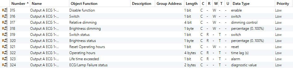
There are 64 DALI devices in the channel. The communication objects of each DALI device are the same and independent of each other. The following is an example of one of the devices:
Fluorescent light

ECG with colour control_RGB(Combined object)


ECG with colour control_HSV(Separated objects)

ECG with colour control_RGBW(Combined object)

ECG with colour control_HSVW(Separated objects)

ECG with colour control_XY colour

ECG with Self-Contained Battery light (non-switchable)
Fig.6.4 “X: ECG”Communication Object
NO. | Name | Object Function | Type | Attribute | DPT | |||||||||||||||||||||||||||||||||||||
315 | Output X ECG y-{{...}} | Disable function | 1bit | C,W | 1.003 enable | |||||||||||||||||||||||||||||||||||||
The communication object is visible when “Disable function” is enable.Used for ECG disable/enable control, the trigger value is defined by the parameter, the device reboot is enabled by default. The name in parentheses changes with the parameter “Description (max 30char.)”. If description is empty, display “Output X ECG y-...” by default. The same below. | ||||||||||||||||||||||||||||||||||||||||||
316 | Output X ECG y-{{...}} | Switch | 1bit | C,W | 1.001 Switch | |||||||||||||||||||||||||||||||||||||
This communication object is not visible when the operation mode is "Permanent mode". Used to switch on or off the ECG, y=1..64. The value for "Switch on" can be defined by a parameter template. See section 5.4.1 for details. | ||||||||||||||||||||||||||||||||||||||||||
317 | Output X ECG y-{{...}} | Relative dimming | 4bit | C,W | 3.007 dimming control | |||||||||||||||||||||||||||||||||||||
This communication object is used for relative dimming of the ECG. The highest bit Bit4 decides to brighten or darken, Bit 0..3 determines the dimming size, and Bit 0..3 is 0 to stop dimming. Refer to object 29 for the correspondence between the value of the relatively dimmed telegram and the change in brightness. | ||||||||||||||||||||||||||||||||||||||||||
318 | Output X ECG y-{{...}} | Brightness value | 1byte | C,W | 5.001 percentage(0..100%) | |||||||||||||||||||||||||||||||||||||
This communication object is not visible when the operation mode is "Permanent mode". It is used to set the brightness value of the ECG. | ||||||||||||||||||||||||||||||||||||||||||
319 | Output X ECG y-{{...}} | Switch status | 1bit | C,R,T | 1.001 Switch | |||||||||||||||||||||||||||||||||||||
This communication object is used to send the switch status of the ECG. | ||||||||||||||||||||||||||||||||||||||||||
320 | Output X ECG y-{{...}} | Brightness status | 1byte | C,R,T | 5.001 percentage(0..100%) | |||||||||||||||||||||||||||||||||||||
This communication object is used to send the brightness status of the ECG. | ||||||||||||||||||||||||||||||||||||||||||
321 | Output X ECG y-{{...}} | Reset Operating hours | 1bit | C,W | 1.015 reset | |||||||||||||||||||||||||||||||||||||
This communication object is used to reset the operating hours of the light to 0. | ||||||||||||||||||||||||||||||||||||||||||
322 | Output X ECG y-{{...}} | Operation hours | 4byte | C,R,T | 13.100 time lag(s) | |||||||||||||||||||||||||||||||||||||
This communication object is used to send the operation hours of the light. Time unit: seconds. Send once every hour.
| ||||||||||||||||||||||||||||||||||||||||||
323 | Output X ECG y-{{...}} | Life time exceeded | 1bit | C,R,T | 1.005 alarm | |||||||||||||||||||||||||||||||||||||
This communication object sends status information when the operation hours of the light exceeds the life time limit of the parameter configuration. | ||||||||||||||||||||||||||||||||||||||||||
324 | Output X ECG y-{{...}} | ECG/light Failure status | 1bit 1byte 2byte | C, R,T | 1.005 alarm 238.600 DALI Diagnostics 237.600 DALI_Control_Gear_ Diagnostics | |||||||||||||||||||||||||||||||||||||
Displayed according to the parameter Object type of ECG /light/converter failure. Used to send failure status of the light and ECG. | ||||||||||||||||||||||||||||||||||||||||||
325 | Output X ECG y-{{...}} | Converter, test start | 1byte | C,W | 20.611 converter test control | |||||||||||||||||||||||||||||||||||||
This communication object is used to start test for converter. Telegrams:
| ||||||||||||||||||||||||||||||||||||||||||
326 | Output X ECG y-{{...}} | Converter, test result | 6byte | C,R,T | 245.600 DALI converter test result | |||||||||||||||||||||||||||||||||||||
This communication object is used to output the test result of converter. Telegram fields LTRF, LTRP, SD, SP, LDTR are defined as following:
| ||||||||||||||||||||||||||||||||||||||||||
327 | Output X ECG y-{{...}} | Converter, status | 2byte | C,R,T | 244.600 DALI converter status | |||||||||||||||||||||||||||||||||||||
This communication object is used to output the status of converter. Telegram fields CM, HS, FP, DP, PP, CF are defined as following:
| ||||||||||||||||||||||||||||||||||||||||||
328 | Output X ECG y-{{...}} | Converter battery, status | 2byte | C,R,T | DTP 246.600 Battery info | |||||||||||||||||||||||||||||||||||||
This communication object is used to output the status of converter battery.
| ||||||||||||||||||||||||||||||||||||||||||
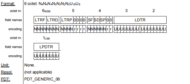
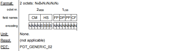
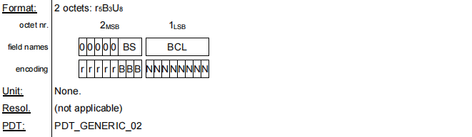
Table 6.4 “X: ECG” Communication Object
NOTE:
Communication objects 325-336 are similar to the objects in Section 6.3 and are not repeated here.
6.5 Channel Communication Object of a Single DALI Sensor

Fig.6.5 “DALI X Motion sensor” Communication Object
NO. | Name | Object Function | Type | Attribute | DPT |
1855 | DALI X Motion sensor y-{{...}} | Output value,movement | 1bit 1byte | C,T | 1.001 switch 5.001 percentage 5.010 counter pulses 17.001 scene number |
This communication object is used to send value when there is a movement, object datatype and range is depending on the parameters. The name in parentheses changes with the parameter “Description (max 30char.)”. If description is empty, display “DALI X Motion sensor y-...” by default. The same below. | |||||
1856 | DALI X Motion sensor y-{{...}} | Disable function,movement | 1bit | C,W | 1.003 enable |
This communication object is used to whether disable movement detection. object value is defined by parameter. | |||||
1857 | DALI X Motion sensor y-{{...}} | End presence (only off telegram) | 1bit | C,W | 1.001 switch |
The communication object is used to receive the switch status of actuator, enter dead time when receive telegram OFF, and suppress presence detection. Telegram ON is no meaning. | |||||
1858 | DALI X Motion sensor y-{{...}} | Failure status,movement | 1bit | C,R,T | 1.005 alarm |
The communication object is used to send the failure status of movement detector to KNX bus. Telegram:
| |||||
1859 | DALI X Motion sensor y-{{...}} | External brightness sensor | 2byte | C,R,T | 9.004 lux(lux) |
The communication object is used to send the brightness value to KNX bus. | |||||
1860 | DALI X Motion sensor y-{{...}} | Output value,brightness alarm | 1bit | C,T | 1.005 alarm |
The communication object is used to send value when brightness value is lower than threshold. object value is defined by parameter. | |||||
Table 6.5 “DALI X Motion sensor” Communication Object