Elevator Access Control and Fire Alarm
You can manage elevator access control through the web interface.
Click a specific floor number (relay-based) to grant access to that floor.
Click Open All to allow access to all floors.
Click Close All to deny access to all floors.
In emergencies, such as a fire, click Turn On Fire Alarm to trigger the alarm and enable access to all floors.
Set it up on the Device> Relay interface.
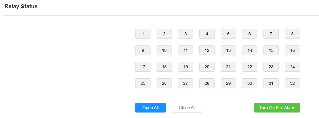
Open All: All relays will stay activated (doors stay open). All relay tabs turn blue.
Close All: All relays will stay deactivated (doors stay closed).
Turn On Fire Alarm: By clicking it, the fire alarm will be triggered and activate all relays at the same time. All relays tab here turns green.
Relay Setting
You can configure the relay activation with a predefined delay and duration. You can also specify the starting floor (relay number). For example, if you set -1 (basement floor 1) as the starting floor, the floor count will begin from -1 as the first floor.
Set it up on the Device> Relay interface.
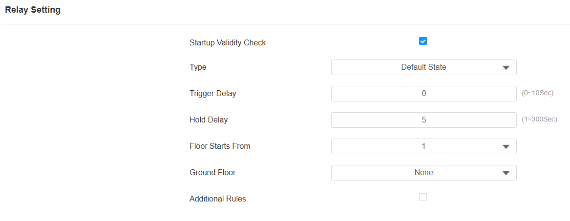
Startup Validity Check: The device will check whether the relay is functioning normally after rebooting or resetting.
Type:
Default State: In this state, the relay either remains open or closed based on its configuration. For example, if the relay is normally open (NO), it will be open until activated.
Invert State: In this state, a normally open relay would be closed (conducting), and a normally closed relay would be open (not conducting). This state is useful for applications where you want to toggle the relay's behavior based on specific conditions.
Trigger Delay (Sec): Set the relay activation delay time (0-10 seconds). The default delay time is 0, meaning immediately activated after triggering.
Hold Delay (Sec): Specify how long the relay stays activated before the door is closed.
Floor Starts From: Set the floor from which the floor count starts. For example, if you select -3, then the 3rd floor in the basement will be considered as the first floor, matched with relay#1 (first floor).
Ground Floor: If there are ground floors between the -1 and 1 floors, configure this option.
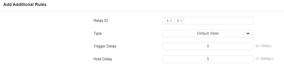
Additional Rules: Check this option if you want to set up the relay type, trigger delay, and hold delay of a specific relay. Then, click Add to add rules.
Relay ID: Choose the relay(s) to be configured.
Open Door via HTTP Command
The device supports remote door unlocking via an HTTP command. Simply enable this feature and input the HTTP command (URL) for the device. This will trigger the relay and open the door, even if the users are away from the device.
Set it up on the Device > Relay interface.
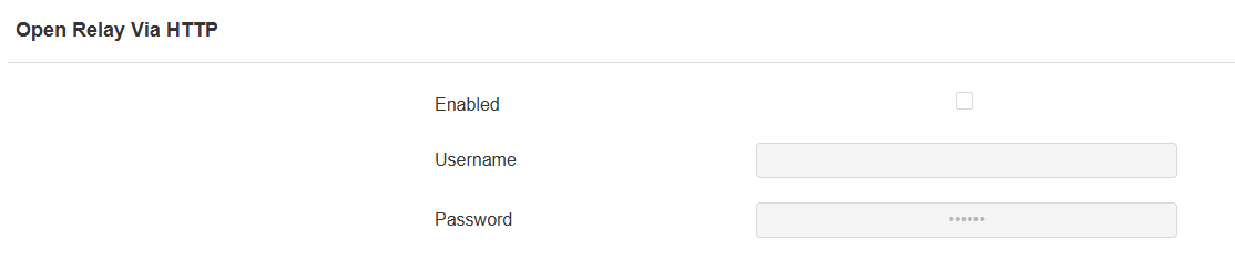
Username: Set a username for authentication in HTTP command URLs.
Password: Set a password for authentication in HTTP command URLs.
Tip
Here is an HTTP command URL example:
.png)
Note
Click here to view how to set up door opening by HTTP commands.
Event-based Elevator Access Control
You can set access control schedules based on events. Choose from your customized schedules and assign them to the relays (floors) for elevator access control. For example, you might create a schedule for house cleaning in a building or for controlling a school gate (open or closed during specific time intervals).
Set it up on the Device > Relay interface. Click Add to apply schedules to relays.
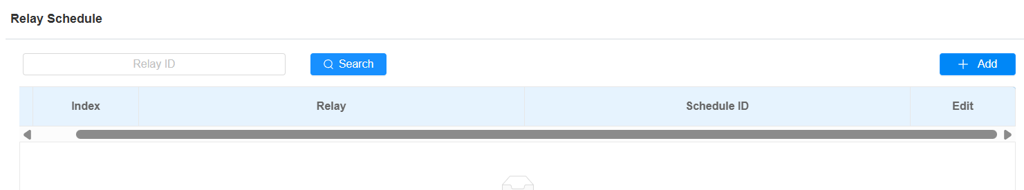
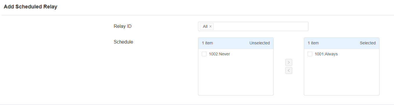
Relay ID: Select relay-based floor number. The floor number can be up to 128 if extra control boards are added.
Schedule Enabled: Make the desired schedule effective by moving it from the left to the right box.
Wiegand
EC33 can be connected to third-party devices such as card readers via Weigand. You set the Wiegand setting based on the technical specification of the third-party device for the integration.
Set it up on the Device > Wiegand interface.
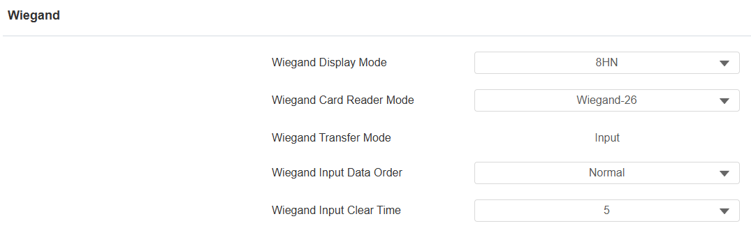
Wiegand Display Mode: Select the same Wiegand card code display format as that of the third-party device (8H10D; 6H3D5D; 6H8D; 8HN; 8HR; RAW, 8HR10D).
Wiegand Card Reader Mode: Select the same Wiegand data transmission format as that of the third-party device (Wiegand 26,34,58).
Wiegand Transfer Mode: It is invariably input because E33 receives the data from the third-party card reader.
Wiegand Input Data Order: Select the Wiegand input data sequence: Normal for the normal data sequence, and Reversed for the reversed order.
Wiegand Input Clear Time: When the interval of entering passwords exceeds the time. All entered passwords will be cleared.
RS485
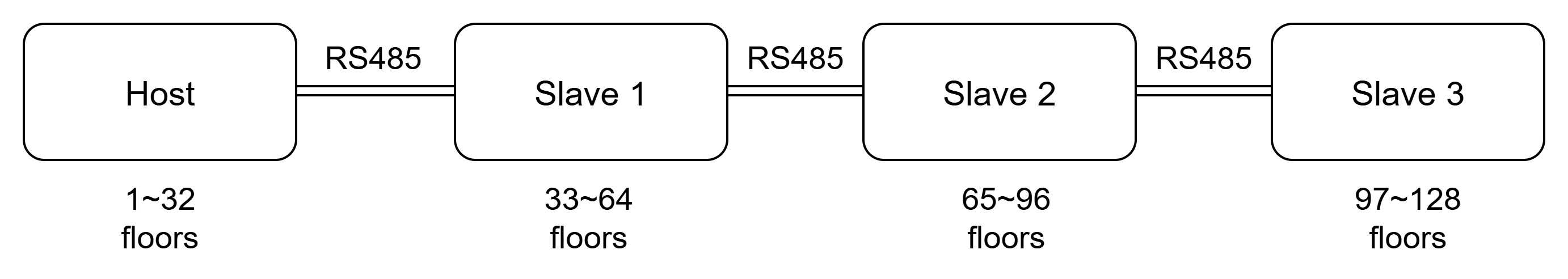
EC33 is scalable from 32 floors to 128 floors by enhancing it with extra control boards via the RS485 interface. You can either choose the RS485A or B interface for the application.
It supports a maximum of 4 boards connected in series, with the main board supporting configurations for floors of 32, 64, 96, or 128. The first slave board’s relays correspond to 33~64 floors.
Set this up on the Device > RS485 interface. Specify which RS485 interface is used for connection before configuration.
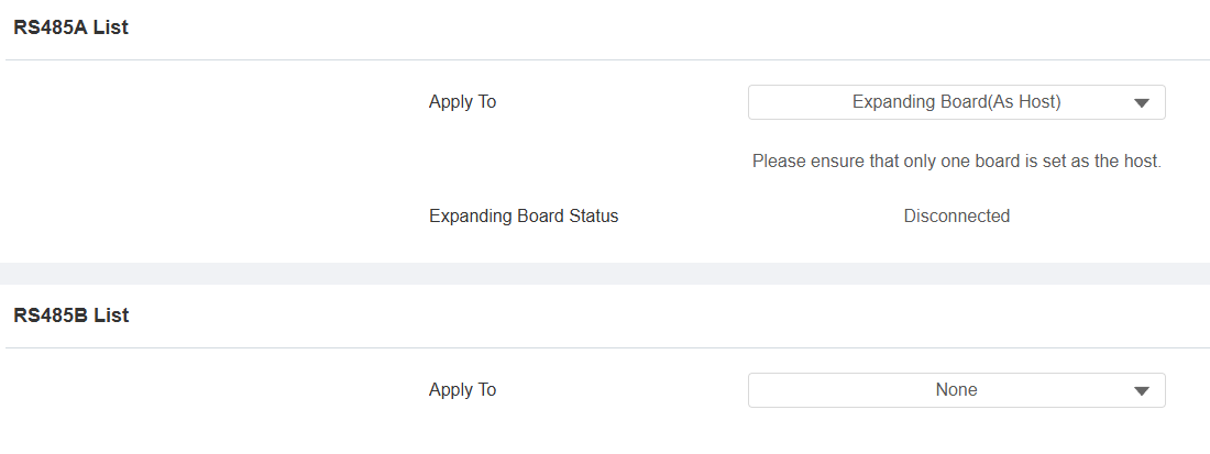
Apply To:
None: Disable the feature.
Expanding Board(As Host): The device works as the main board that can be connected to a slave board. The floor number changes occur on this device’s web interface.
Expanding Board(As Slave): The device works as the slave board that can be connected to another slave board.
Expanding Board Status: Display whether the expanding board is connected.
Mailbox Control
The device supports the integration with KonNaD mailboxes. When the mail carrier delivers the letter, the device receives the message and sends a notification to the resident’s SmartPlus App and/or indoor monitor.
Click here to view the detailed configuration.
Set this feature up on the Device > Mailbox interface.
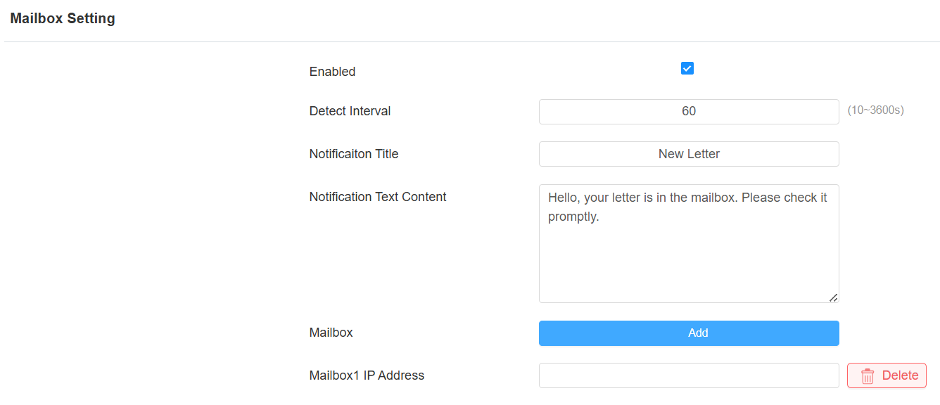
Detect Interval: Define the interval for the device to detect the mailbox. The default is 60 seconds.
Notification Title: Customize the notification title displayed on the SmartPlus App and/or indoor monitor.
Notification Text Content: Customize the notification content displayed on the SmartPlus App and/or indoor monitor.
Mailbox IP Address: Click Add to input the mailbox’s IP address.
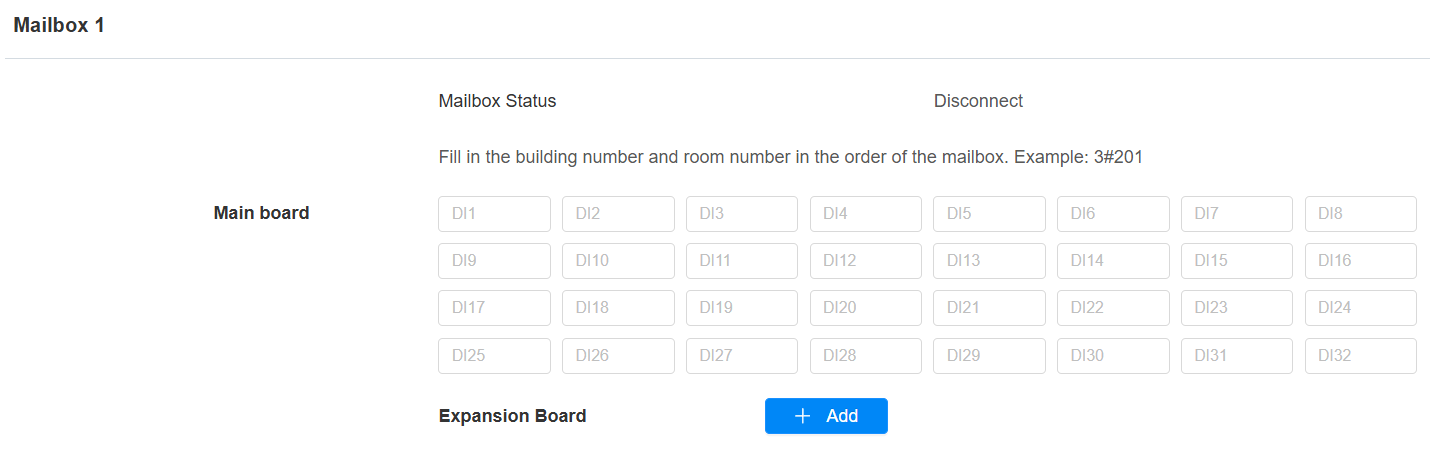
Mainboard: Specify which DI to trigger when the mail is delivered. And fill in the Building Name#APT Number where the resident lives in the target DI field. For example, Building A#203.
Expansion Board: If the mailbox’s mainboard is connected to an expansion board, click +Add to configure it.