The parameter settings interface Page x - HVAC, as shown in Figure 2.4.3, primarily configures parameters for fan control and some basic controls for HVAC.

Figure2.4.3: Page x - HVAC interface
Temperature reference from
Set the source of temperature reference for HVAC.
Options:
Internal sensor: When selecting internal sensor as the reference, the temperature is determined by the “Internal sensor setting” in the parameter interface “General sensor”.
External sensor
Internal and External sensor combination
The following two parameters are visible when an external temperature sensor option is available:
- Time period for request external sensor [0 .. 255]min
Set the time period for the device to send read requests to the external temperature sensor.
Options: 0 ... 255
- Read external sensor after restart
Specify whether the device reads external sensor data after a reset. Options:
No: Read requests are held until the cycle time ends after bus power reset or programming completion, rather than being sent immediately.
Yes: Read requests are sent to the external temperature sensor device following bus power reset or programming completion.
This parameter is visible when HVAC temperature reference is “Internal and external sensors combination”.
- Combination ratio
Set the proportion of temperature measurement between the internal and external sensors.
Options:
10% Internal to 90% External
20% Internal to 80% External
…
80% Internal to 20% External
90% Internal to 10% External
For example, if the ratio is set to “40% Internal to 60% External”, the internal sensor contributes 40% and the external sensor 60% to the control temperature calculation. This means the control temperature = (temperature from the internal sensor×40%)+ (temperature from the external sensor×60%). The HVAC function of the device will manage and display the resulting temperature.
If one sensor fails when both sensors are used for detection, the temperature value detected by the functioning sensor will be used.
Control value after temp.error[0..100%](If 2-point control,set value ’0 ’=0,set value ’>0 ’=1)
Set the control value used when a temperature error occurs.
Options: 0..100
In the two-point control mode, this parameter value of 0 results in a control value of 0, while this parameter value greater than 0 yields the control value of 1.
Power on/off status after download
Set the on/off status of the HVAC interface after downloading the application program.
Options:
Off
On
Power on/off status after bus recovery
Set the on/off status of the HVAC interface after bus power is restored.
Options:
On: When power is restored, the device will be in the powered-on state, and the interface will be operational. The HVAC system will determine the current control status by computing based on the control mode.
Off: When power is restored, the device will be in the powered-off state, and the interface will not be operational with no computation or control occurring.
Before power off: Upon power restoration, the device returns to its status prior to power off. If it is powered on, the HVAC system determines the current device control status based on the control mode.
Control type of fan speed
Set the data type of fan speed.
Options:
Disable: Not allowed to control fan speed.
1bit: The object type of fan speed control is 1bit.
1byte: When the object type of fan speed control is 1byte, the HVAC_Fan parameter configuration sub-interface becomes visible. To HVAC_Fan_1byte to view details.
- Fan speed auto
When the “Control type of fan speed” parameter is set to 1bit or 1byte, this parameter becomes visible, allowing you to enable automatic control of fan speed.
Options:
Disable
Enable: Automatic control for fan speed is available.
HVAC control mode
Set the output control mode of the HVAC system.
Options:
Heating
Cooling
Heating and Cooling: Support both heating and cooling. When selected, the following two parameters are visible:
- Heating/Cooling status after restart
Set the heating/cooling output control mode after the device restarts.
Options:
Heating
Cooling
As before reset: Upon power restoration, the device returns to its status prior to power off. If the application program is re-downloaded, the device's control mode upon startup becomes uncertain and requires manual selection.
- HVAC control system
Set the type of HVAC control system, specifically the pipe type for water distribution.
Options:
2 pipes system: Only one supply line and one return line serve for heating and cooling, with both hot water and cold water controlled by a single valve.
4 pipes system: Contain both hot water supply with return lines and a chilled water supply with return lines, requiring two valves to control the hot water and cold water respectively.
HVAC operation mode
Set whether to enable the operation mode of the HVAC system.
Options:
Disable
Enable: When selected, the following four parameters become visible.
- Operating mode switchover
Set the object type for switching operating modes.
Options:
4x1bit: When selected, four 1bit objects are visible:
HVAC Input -- Comfort mode
HVAC Input -- Economy mode
HVAC Input -- Frost/Heat protection mode,
HVAC Input -- Standby mode
Activating a mode triggers the corresponding object to send a telegram “1”; otherwise, it transmits “0”.
1byte: When selected, the object “HVAC Output -- HVAC mode” is visible. The telegram values sent and their meanings are as following:
1: Comfort mode
2: Standby mode
3: Economy mode
4: Frost/Heat protection mode
- Operating mode status
Set the object type for operating mode status feedback.
Options:
4x1bit: The device switches among different modes based on the ON or OFF telegrams received by the following four 1-bit objects:
HVAC Input-- Comfort mode
HVAC Input-- Economy mode
HVAC Input-- Frost/Heat protection mode
HVAC Input-- Standby mode
When the values of the first three objects are all 0, the operation mode is set to Standby mode.
1byte: The device updates to the corresponding mode based on the received telegram values as follows:
1: Comfort mode
2: Standby mode
3: Economy mode
4: Frost/Heat protection mode
- Controller status after restart
Set the operating mode of the controlled device after the device restarts.
Options:
Standby mode
Comfort mode
Economy mode
Frost/heat protection
- Extended comfort mode[0.. 255,0=inactive]min
Set the delay time for automatically changing from Comfort mode to Economy mode.
Options: 0 ~ 255
Note
This parameter is only applicable to the switching between Economy mode and Comfort mode.
When the set value is 0, it indicates Comfort mode will not automatically return to Economy mode.
When the value is between 1 and 255, the Comfort mode will automatically switch back to Economy mode after set delay time.
Basic setpoint temperature [℃]
This parameter is visible when the operating mode of the HVAC system is disabled. It specifies the baseline value for the set temperature.
Options:
10
10.5
...
35
This setting can be modified using the bus object “Setpoint adjustment”. The new setting is saved after a bus power reset.
Min. /Max. set temperature [5..40]℃
Specify the range of temperature setpoints. The minimum value must be set lower than the maximum value; otherwise, it will revert to the default setting. If the set temperature exceeds the defined limits, it will be automatically adjusted to fit within the specified range.
Voice command ID[120..129]
Not applicable for HyPanel.
The following parameters are visible when the “Control type of fan speed” is set to “1byte”, as shown in Figure 2.4.3-2.
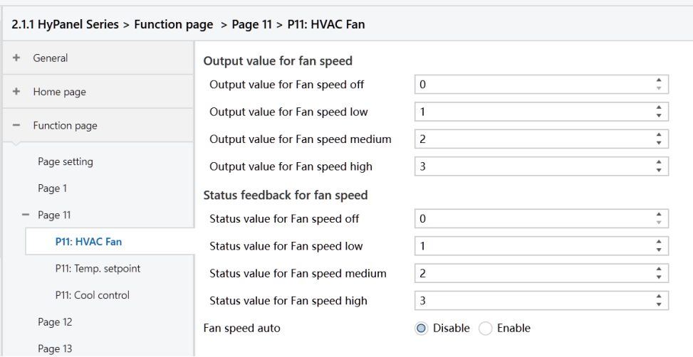
Figure2.4.3-2: Page x - HVAC Fan_1byte interface
- Output value for Fan speed off/low/medium/high
Define the values to switch to each fan speed level.
Options: 0 ~ 255.
- Status value for Fan speed off/low/medium/high
Set the status feedback values for each fan speed. The device will update the displayed fan speed based on the feedback values.
Options: 0 ~ 255.
The following parameter is visible when HVAC operation mode is enabled:
- Setpoint method for operating mode
Set the actual adjusting method for panel temperature setpoints.
Options:
Relative: The temperature settings for Energy-saving and Standby modes are based on the defined baseline temperature setpoint.
Absolute: Each mode has its own temperature setpoint.
The following parameters are visible when HVAC operating mode is enabled and the temperature setpoint adjusting method is set to “Relative”, as shown in Figure 2.4.3-3.

Figure2.4.3-3: Page x--HVAC Temp Relative interface
- Basic setpoint temperature [℃]
Set the baseline setpoint temperature value, which determines the setpoint temperature for Comfort mode.
Options:
10
10.5
...
35
This setting can be modified using the bus object “Setpoint adjustment”. The new setting is saved after a bus power reset.
- Reduced heating in standby mode [0.. 10]℃
- Increased cooling in standby mode [0.. 10]℃
Set the temperature setpoint for Standby mode.
Options: 0 ~ 10 [℃]
For heating: Standby mode temperature setpoint = Baseline value - The value specified by this parameter.
For cooling: Standby mode temperature setpoint = Baseline value + The value specified by this parameter.
- Reduced heating during economy mode [0.. 10]℃
- Increased cooling during economy mode [0.. 10]℃
Set the temperature setpoint for Economy mode.
Options: 0 ~10 [℃]
For heating: Standby mode temperature setpoint = Baseline value - The value specified by this parameter.
For cooling: Standby mode temperature setpoint = Baseline value + The value specified by this parameter.
- Actual Temp. threshold in frost protection[5.. 10]℃ (for heating)
Set the temperature setpoint for Frost protection mode in heating.
Options: 5 ~ 10 [℃]
In Frost protection mode, when the room temperature drops to the value set by this parameter, the controller triggers a control telegram to activate heating actuators to work, preventing the temperature from falling too low.
- Actual Temp. threshold in heat protection[30..40]℃ (for cooling)
Set the temperature setpoint for overheat protection mode in cooling.
Options: 30 ~ 40 [℃]
In overheat protection mode, when the room temperature rises to the value set by this parameter, the controller triggers a control telegram to activate cooling actuators to work, preventing the temperature from rising too high.
The following parameters are visible when HVAC operation mode is enabled and the temperature setpoint adjusting method is set to “Absolute”, as shown in Figure 2.4.3-4.

Figure2.4.3-4: Page x-- HVAC Temp Absolute interface
- Setpoint Temp. in comfort mode [5.. 40]℃
- Setpoint Temp. in standby mode [5.. 40]℃
- Setpoint Temp. in economy mode [5.. 40]℃
- Setpoint Temp. in frost protection mode [5.. 40]℃(for heating)
- Setpoint Temp. in heat protection mode [5.. 40]℃(for cooling)
The above parameters are used to configure temperature setpoints for specific modes.
Options: 5 ~ 40 ℃.
The following are the parameters for heating/cooling control, as shown in Figure 2.4.3-5.

Figure: Page x--HVAC Heat&Cool control interface
Type of Heat/Cool control
Set heating/cooling control types, applicable for different temperature controllers.
Options:
Switching on/off (use 2-point control)
Switching PWM (use PI control)
Continuous control (use PI control)
Invert control value
Determine the control value sent to the control object is normal or inverted, ensuring compatibility with different valve types.
Options:
No
Yes: After the control value is inverted, it is sent to the bus via the object.
The following two parameters apply to two-point control:
- Lower Hysteresis [0.. 200]*0.1℃
- Upper Hysteresis [0.. 200]*0.1℃
Set temperature hysteresis for HVAC heating or cooling.
Options: 0 ~ 200
In the heating process
Heating stops once the actual temperature (T) exceeds the setpoint temperature plus the upper hysteresis value.
Heating starts when the actual temperature (T) falls below the setpoint temperature minus the lower hysteresis value.
For example, with a lower hysteresis of 1°C and an upper hysteresis of 2°C, and a setpoint temperature of 22°C:
Heating stops if T exceeds 24°C.
Heating starts if T falls below 21°C.
Heating maintains its current state if T is between 21°C and 24°C.
In the cooling process
Cooling stops when the actual temperature (T) falls below the setpoint temperature minus the lower hysteresis value.
Cooling starts when the actual temperature (T) exceeds the setpoint temperature plus the upper hysteresis value.
For example, with a lower hysteresis of 1°C and an upper hysteresis of 2°C, and a setpoint temperature of 26°C:
Cooling stops if T falls below 25°C.
Cooling starts if T exceeds 28°C.
Cooling maintains its current state if T is between 25°C and 28°C.
Note
Two-point control is a simple method requiring both upper and lower hysteresis values to be set. Consider the following impacts when setting hysteresis temperatures:
1.A smaller hysteresis range results in less temperature variation but increases bus load due to frequent control value transmissions.
2.Conversely, a wider hysteresis range reduces switching frequency, but may cause uncomfortable temperature fluctuations.
The following two parameters apply to PI control.
- Heating speed
- Cooling speed
Set the response speed of the heating or cooling PI controller. Different response speeds match various environments.
Options:
Hot water heating (5K/150min)
Underfloor heating (5K/240 min)
Electrical heating (4K/100min)
Split unit/ Fan coil unit (4K/90min)
User defined
Options:
Cooling ceiling (5K/240min)
Split unit (4K/90min)
Fan coil unit(4K/90min)
User defined
When the “User defined” is selected in “Heating/Cooling speed”, the following parameters are visible.
- Proportional range[10 to 100]*0.1℃ (P value)
- Reset time[0 to 255]min (I value)
Set PI values of PI controllers.
Parameter PWM cycle time [1.. 255] min
This parameter is exclusively accessible when the "Type of Heat/Cool Control" is configured as "Switching PWM (use PI control)". It defines the cycle time for the control object to periodically transmit switching control values. The object sends on/off telegrams depending on the duty cycle of the control value.
For instance, with a set cycle time of 10 minutes and a control value of 80%, the object will send an "on" telegram for 8 minutes and an "off" telegram for 2 minutes in each cycle. This cycle persists continuously. If the control value is changed, the duty ratio of the object's on/off telegram will adjust accordingly, while the period remains constant at the time set by the parameter.
Options: 1 ~ 255
Note
The PI control values of “Switching PWM (use PI control)” and “Continuous control (use PI control)” are the same. The difference lies in their control object:
The control object of "Continuous control" directly outputs the PI value (1 byte)
The control object of “Switching PWM” outputs an "on/off" control telegram based on the duty cycle of the PI control value.
Send control value on change by [0..100%, 0=inactive]
This parameter is visible when the control type is “Continuous control (use PI control)”. It specifies the threshold at which a change in the control value prompts its transmission to the bus.
Options: 0 ~ 100. 0=inactive.
Cyclically send control value [0.. 255]min
Set the time period for cyclically sending the control value to the bus.
Options: 0 ~ 255
In the PI control mode, the recommended predefined control parameters for each PI controller in the heating or cooling system are as follows:
Heating system
Heating Type
P Value
I Value (Integration time)
Recommended PI Control Type
Recommended PWM Cycle Period
Hot water Heating
5K
150min
Continuous/PWM
15min
Underfloor heating
5K
240min
PWM
15-20min
Electrical heating
4K
100min
PWM
10-15min
Split unit
4K
90min
PWM
10-15min
Fan coil unit
4K
90min
Continuous
/
Cooling system
Heating Type | P Value | I Value (Integration time) | Recommended PI Control Type | Recommended PWM Cycle Period |
Cooling ceiling | 5K | 240min | PWM | 15-20min |
Split unit | 4K | 90min | PWM | 10-15min |
Fan coil unit | 4K | 90min | Continuous | / |
User defined
When the parameter “Heating/Cooling speed” is set to “User defined”, the values of P (proportionality) and I (integration time) can be set through parameter settings. When adjusting the parameters, refer to the fixed PI value mentioned in the above table. Even slight modifications to these control parameters can result in significantly different control behaviors.
Moreover, it's crucial to set the integration time appropriately. A large integration time value will lead to slow adjustments and subtle oscillations. Conversely, a small integration time value can cause rapid adjustments but may result in oscillations. A value of 0 for the integral time indicates that the integral term is not used.
Settings and effects of User-defined parameters:
Parameter setting | Effect |
K: the proportion range is too small | Rapid adjustment; overshoot will occur |
K: the proportion range is too large | Slow adjustment, without overshoot |
TN: the integration time is too short | Rapid adjustment; oscillation will occur |
TN: the integration time is too long | Slow adjustment, with subtle oscillation |