This document introduces commonly used logic modules in ETS, including their functions, parameter descriptions, and configuration examples. It is intended to help you implement practical automation logic in KNX projects.
Function Description
Logical Operations: AND/OR/XOR
Function | Logic Rule | Example Application |
AND | The output is true (1) only when all input conditions are true. If any input is false (0), the output becomes false. | Determine “someone is home” only when both the motion sensor detects presence and the door/window sensor is opened. |
OR | The output is true (1) when any inputs is true. Only when all inputs are false does the output become false. | If any motion sensor detects presence, consider the room occupied. |
XOR | The output is true (1) when the two inputs have different states (one is 1 and the other is 0). If both inputs are the same, the output is false. | Implement two-way stair lighting control using switches at the top and bottom of the stairs. |
Gate Forwarding
Logic Rule
Forward a single input to different output targets based on scene numbers. This allows one trigger to perform different actions in different scenes.
Example
A single button can control different lights depending on the active scene.
Threshold Comparator
Logic Rule
Compare an input value (e.g., brightness, temperature, occupancy count) with a predefined threshold and output a 0/1 result.
Example
When an air quality sensor detects poor air quality, output “1” to automatically turn on the ventilation system.
Format Convert
Logic Rule
Convert data from one KNX Data Point Type (DPT) to another, enabling communication between devices that use different formats.
Example
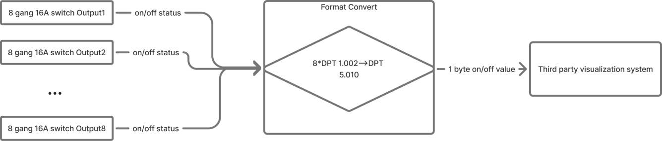
An 8-channel switch module provides eight independent 1-bit states, while a visualization system may only accept a single 1-byte value to represent all switch states. Format Conversion combines and converts the states into the required 1-byte format.
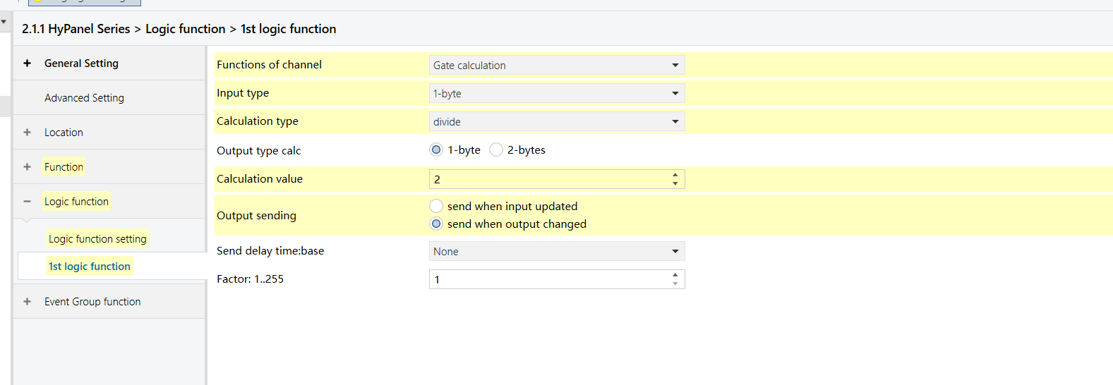
Gate Calculation
Logic Rule
Perform calculations (addition, subtraction, multiplication, division) or range evaluation on input data and outputs the result.
Example
Convert a 0-1000 lux brightness value into a 0-100% output signal (brightness ÷ 10) for curtain position control.
Logic Function Parameters in ETS
All logic-related parameters can be found in Parameter setting interface “Logic function setting”.
Configuration Examples
The following examples demonstrate how to configure and apply each logic function.
You may replace the sample devices (e.g., occupancy sensor) with those used in your actual project.
AND/OR Logic
Example Description
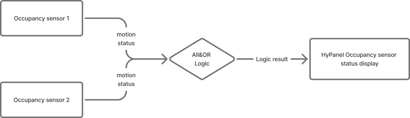
When both occupancy sensors detect “no presence”, the HyPanel shows “no one present”.
If either sensor detects presence, the HyPanel displays “someone present.”
Configuration Flowchart
Configuration Steps
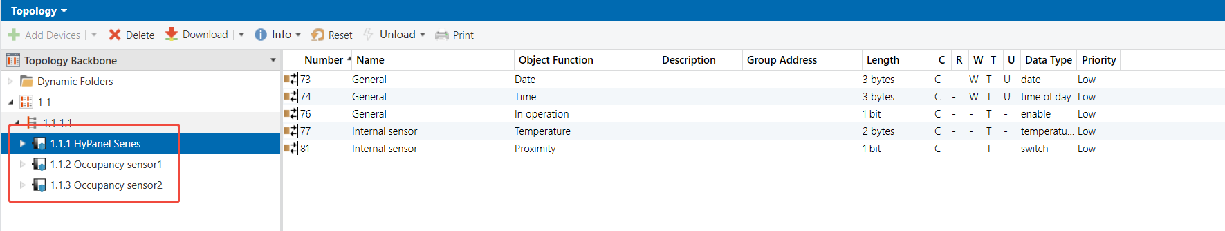
Topology
Parameters & Group Objects
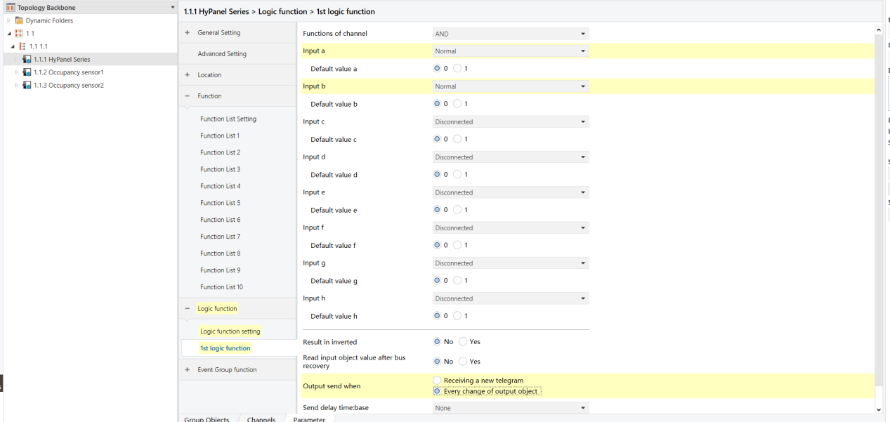
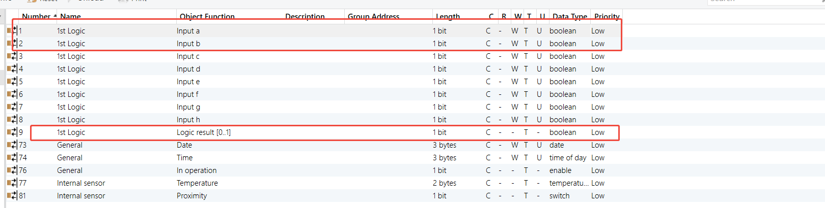
HyPanel - AND Logic Function
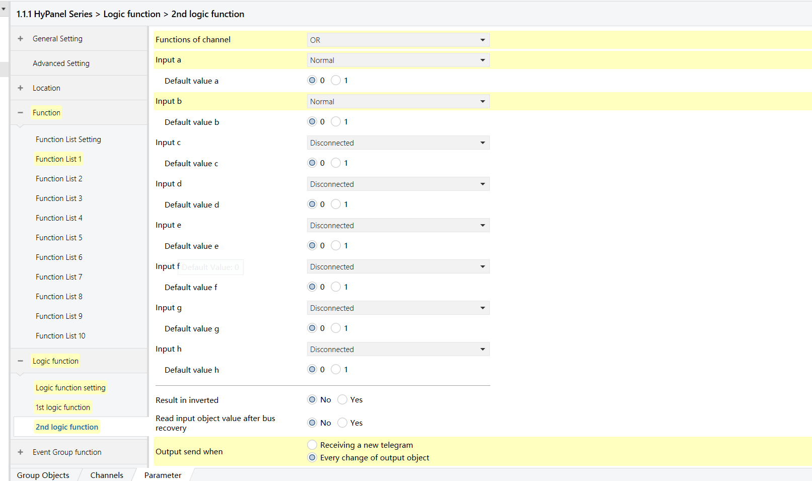
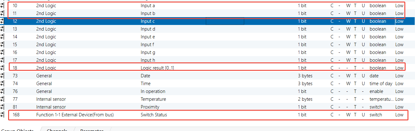
HyPanel - OR Logic Function
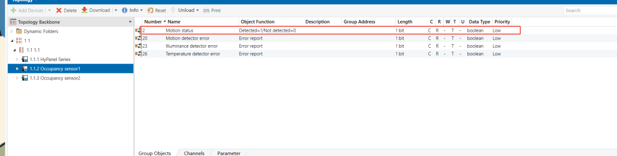
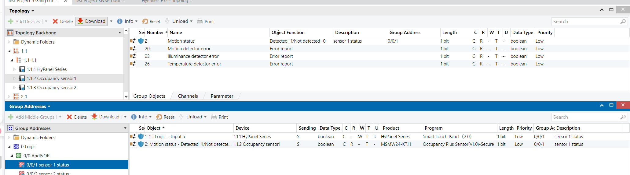
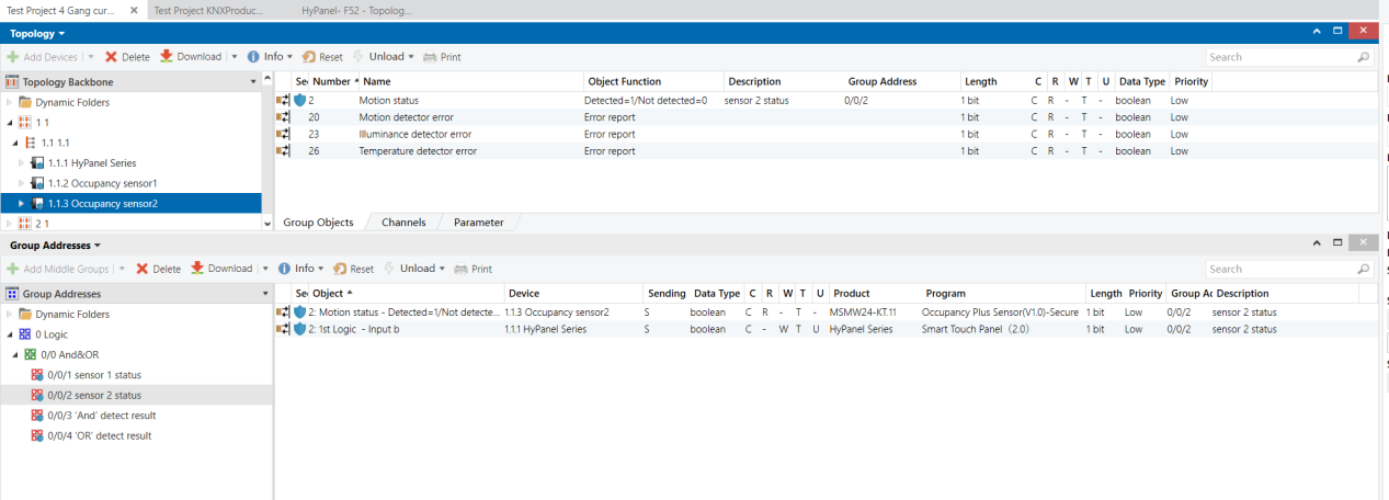
Occupancy Sensor 1 & 2 - Group Objects (No Presence)
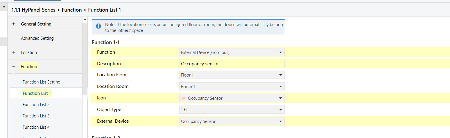
HyPanel - Occupancy Sensor Function Configuration
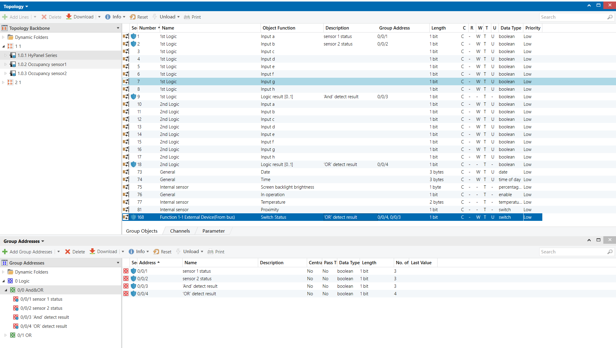
Group Address Assignment
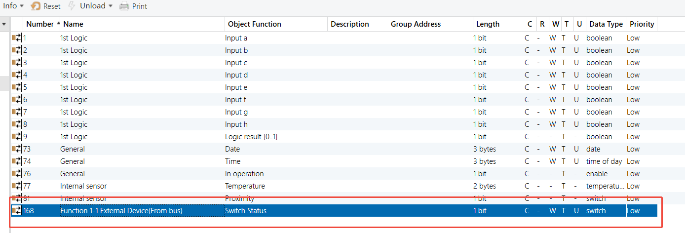
HyPanel
NOTE:
Link both the AND and OR logic output objects to the HyPanel’s presence sensor object.
Occupancy Sensor 1&2
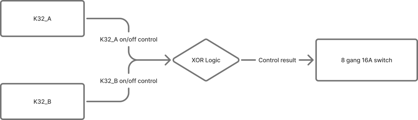
XOR Logic
Example Description
Two Aura series K32 button panels (K32_A and K32_B) control the same stair light (8-Gang 16A switch module). Pressing either switch toggles the light.
NOTE:
Without XOR logic, two-way control is still possible, but the switch may require two presses to synchronize the state.
Configuration Flowchart
Configuration Steps
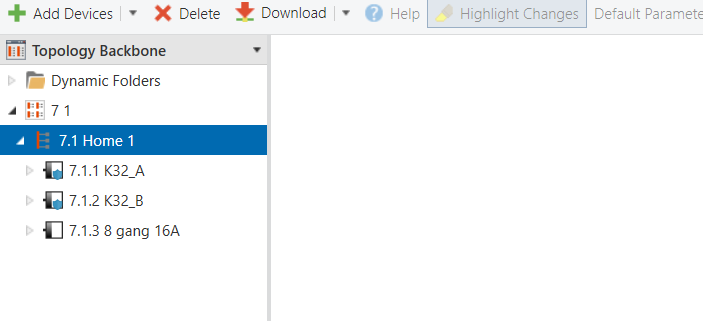
Topology
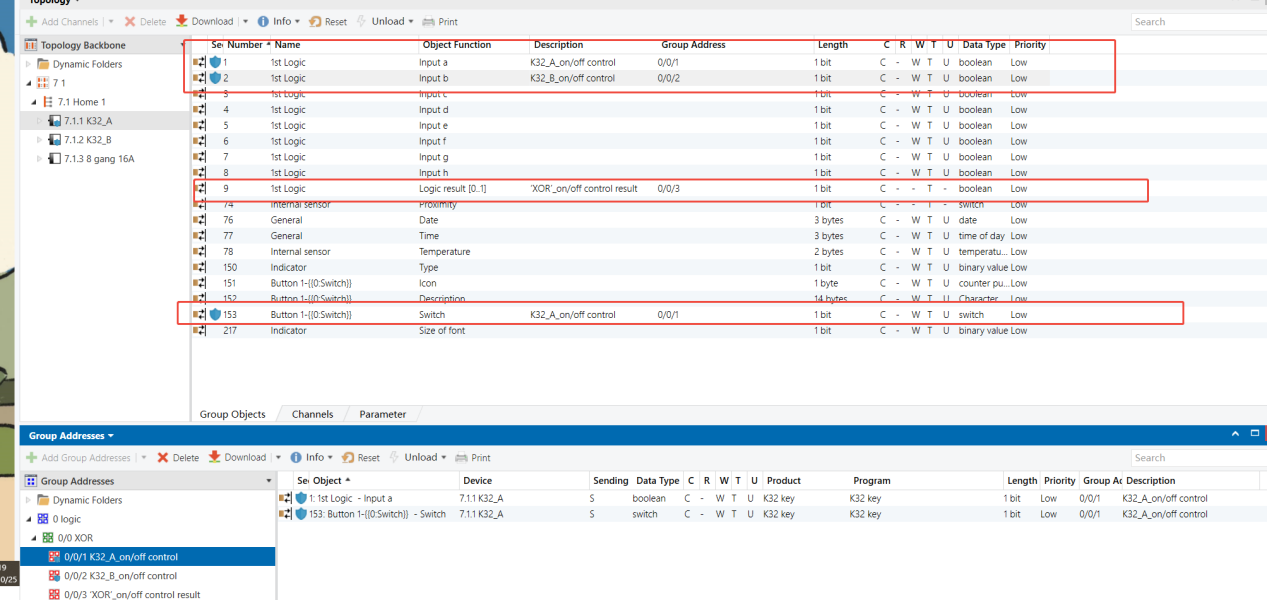
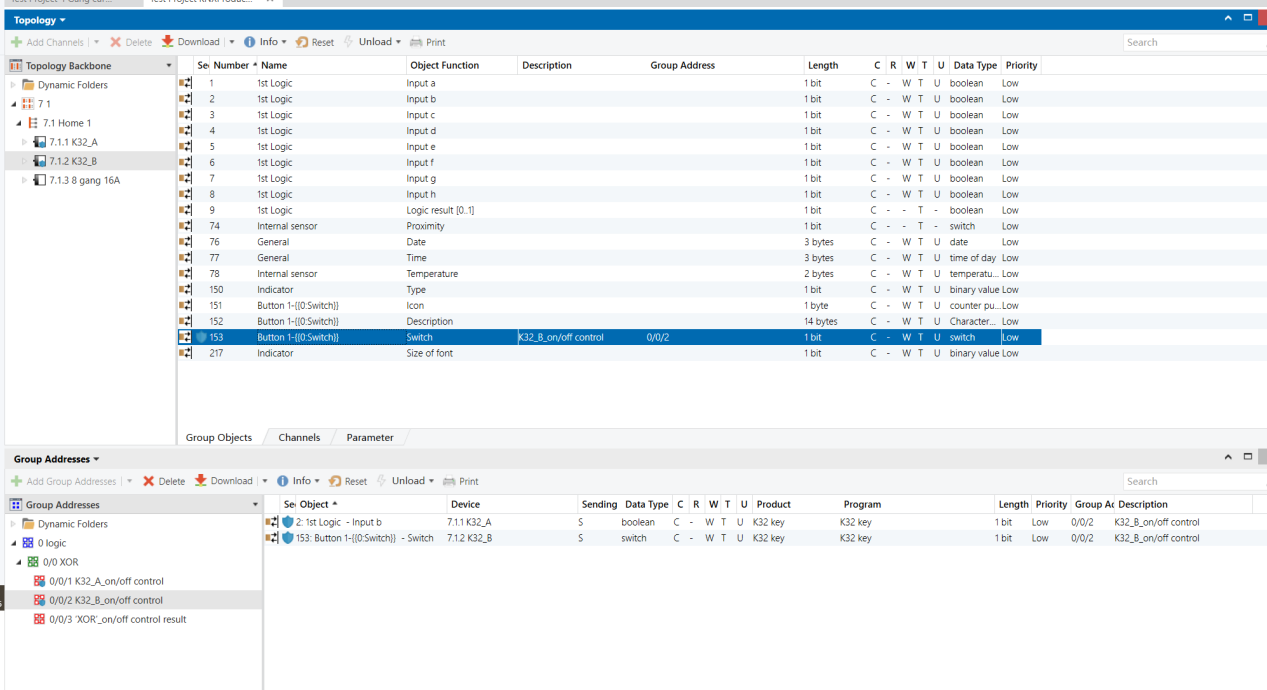
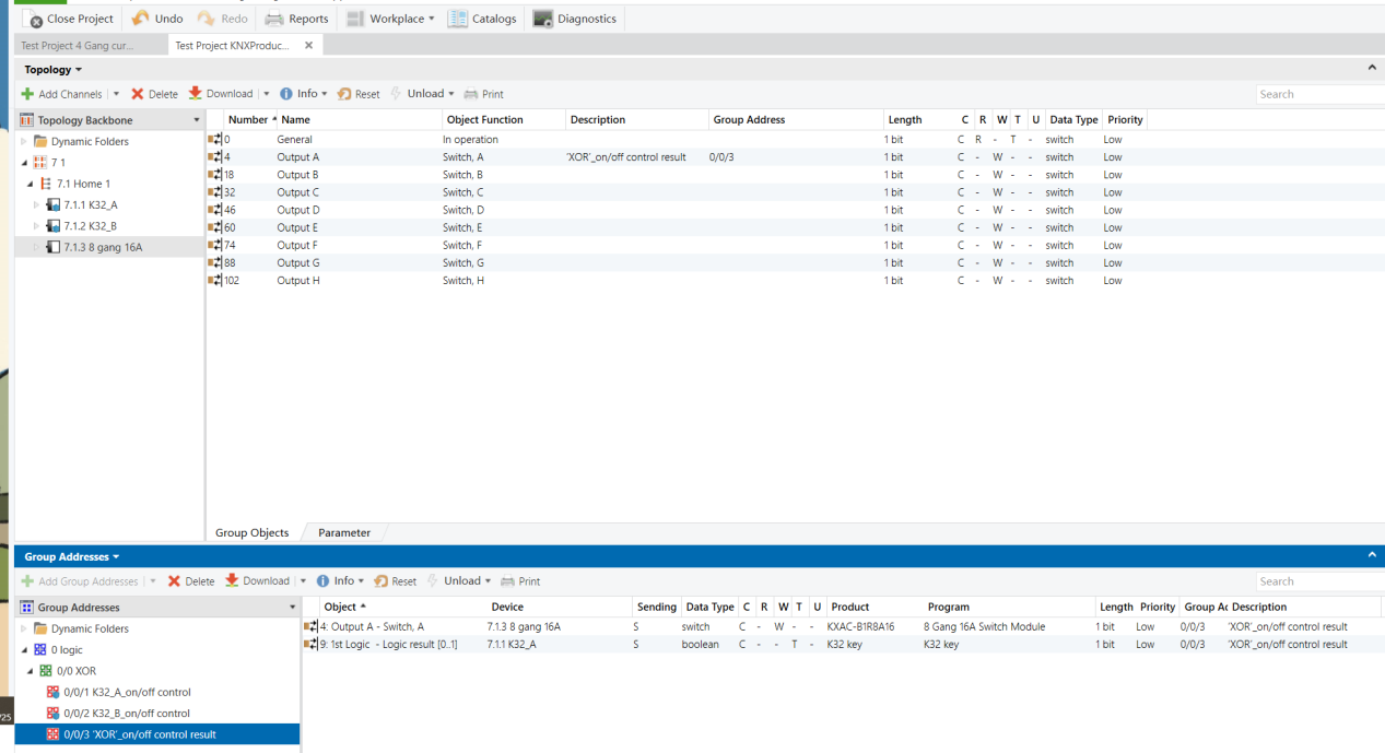
Parameters & Group Objects
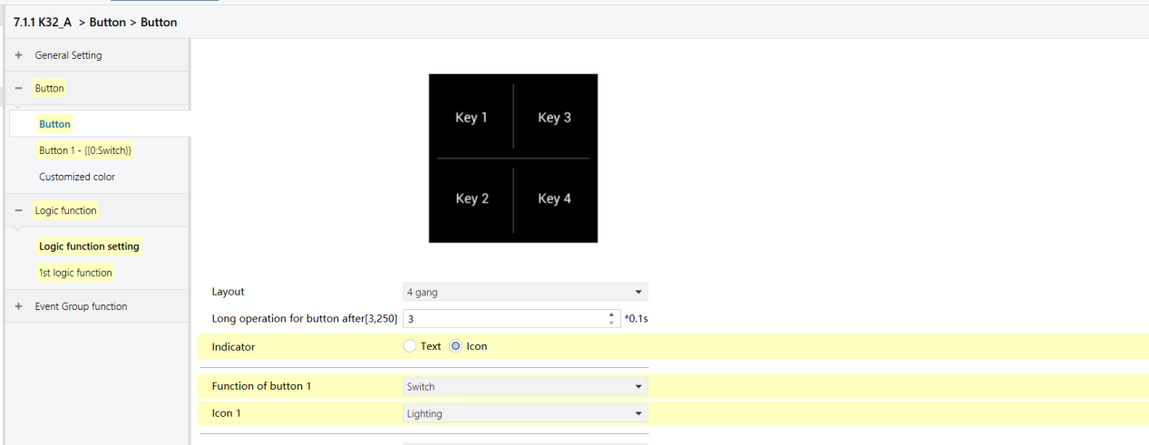
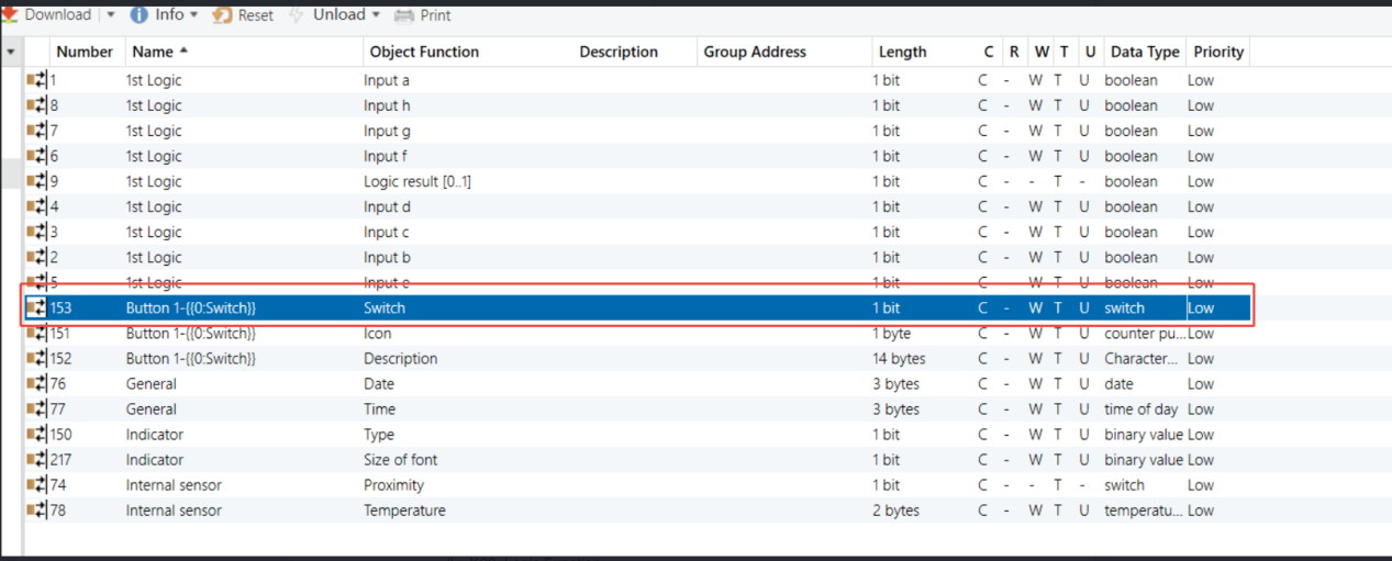
K32_A - Button Function (same on K32_B)
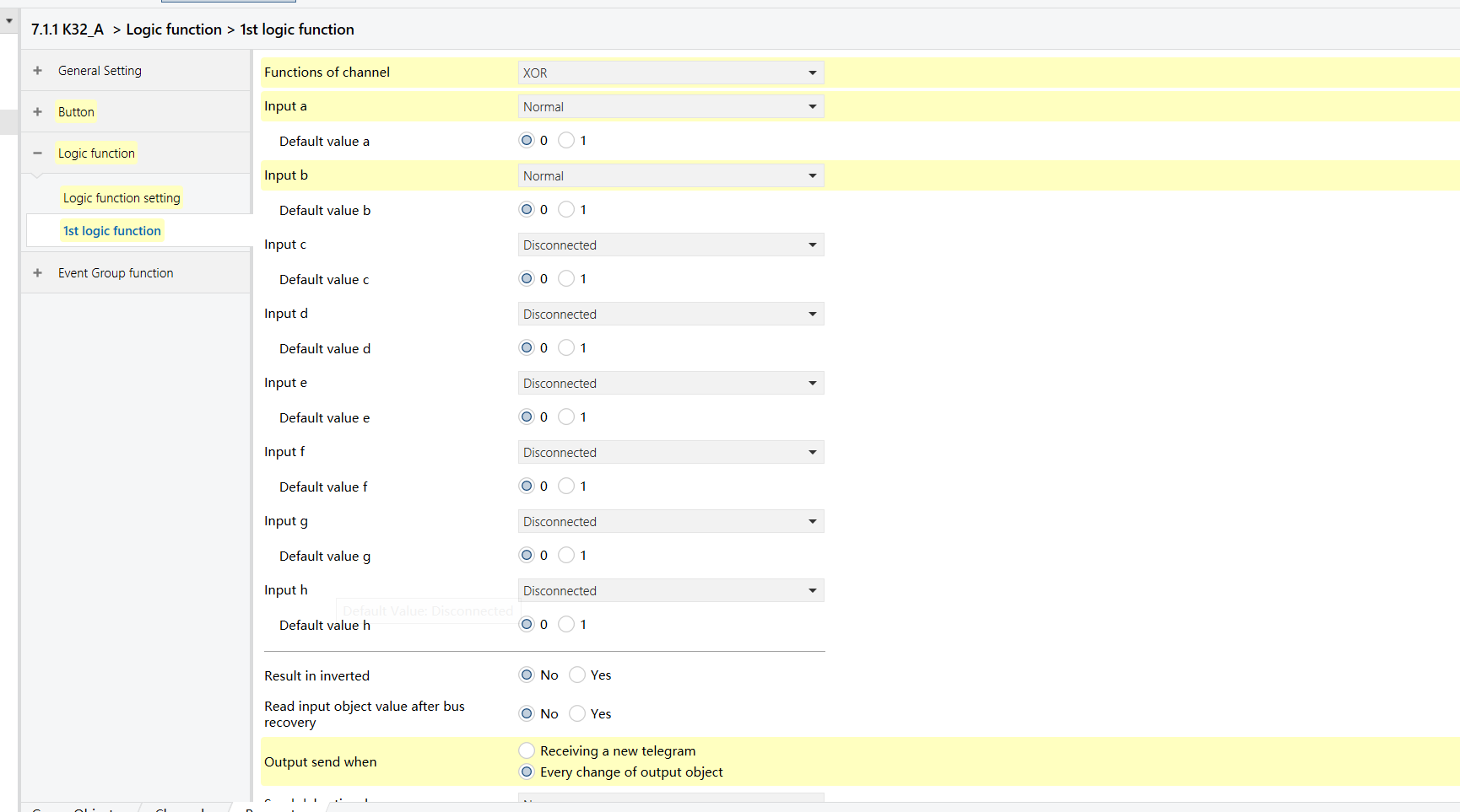
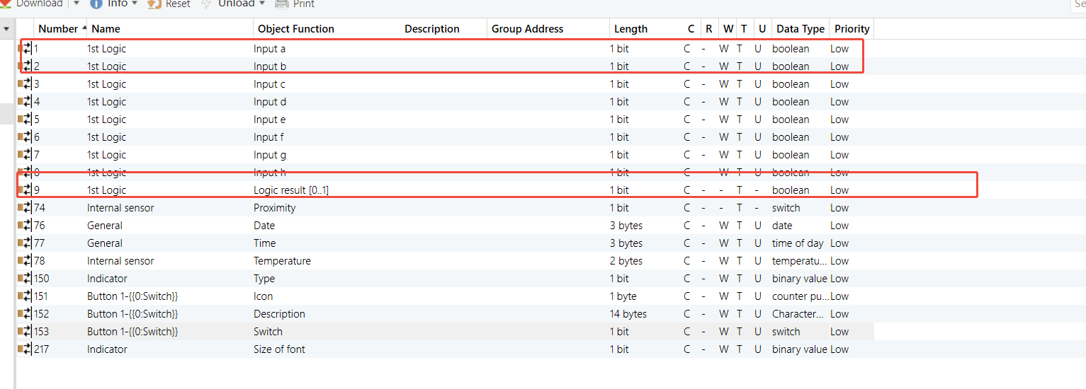
K32_A - XOR Logic Function (same on K32_B)
Group Address Assignment
K32_A
K32_B
8-Gang 16A Switch Module
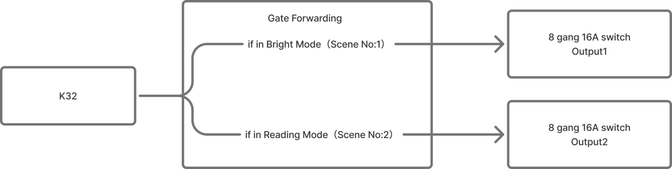
Gate Forwarding
Example Description
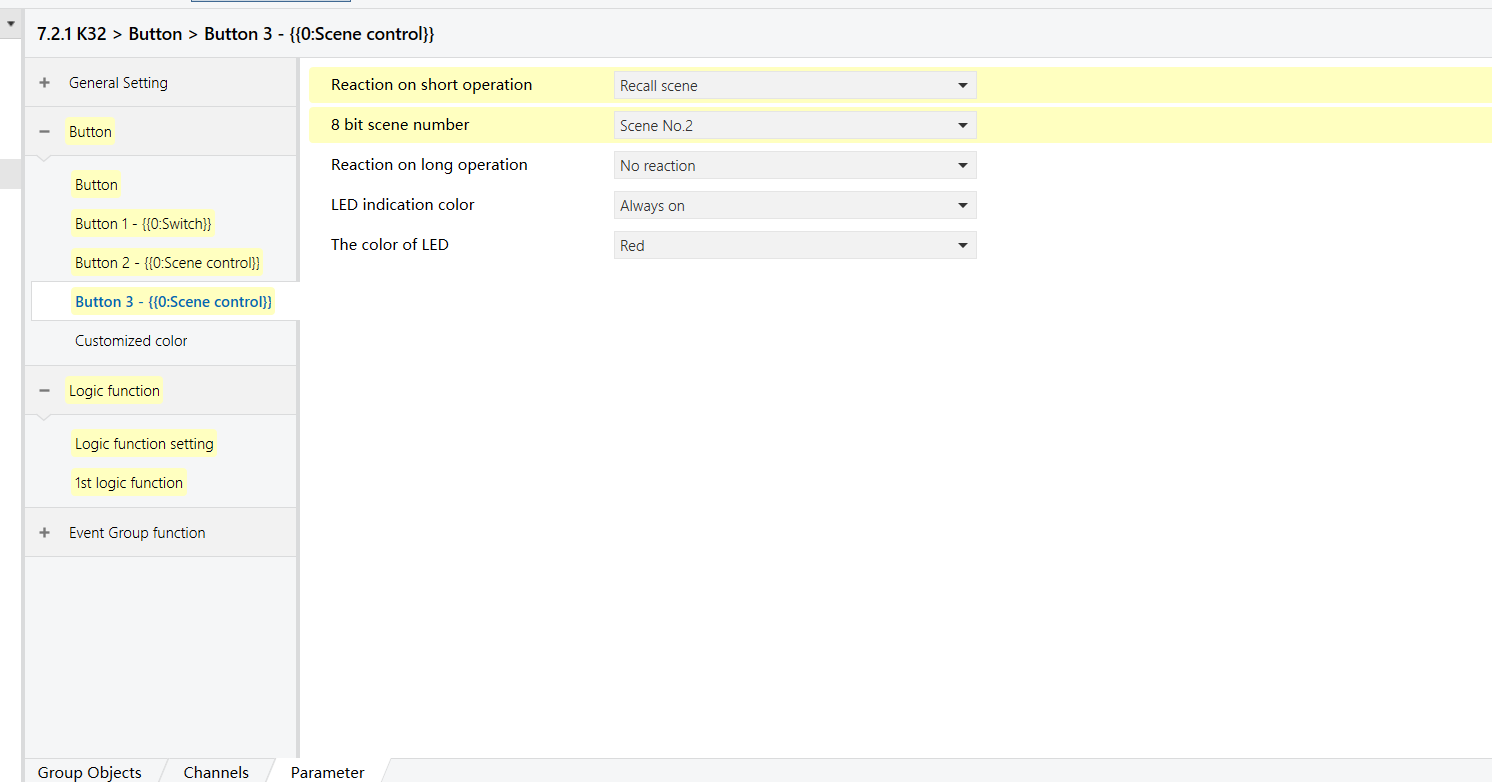
A button on a bedside K32 panel controls different lights depending on the active scene:
Bright scene: The button controls main light (Output 1 of the 8-Gang 16A switch module)
Reading scene: The button controls the desk lamp (Output 2 of the 8-Gang 16A switch module)
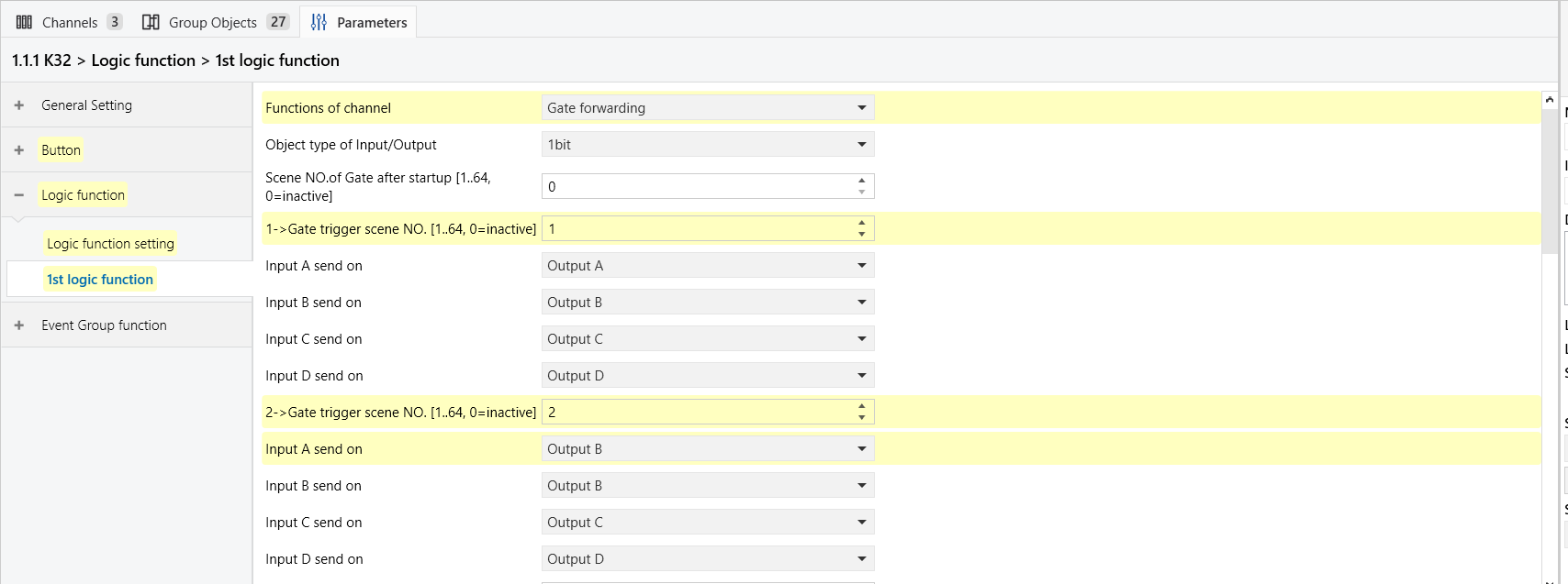
For this example, assume the scene numbers are:
Bright = 1, Reading = 2.
Configuration Flowchart
Configuration Steps
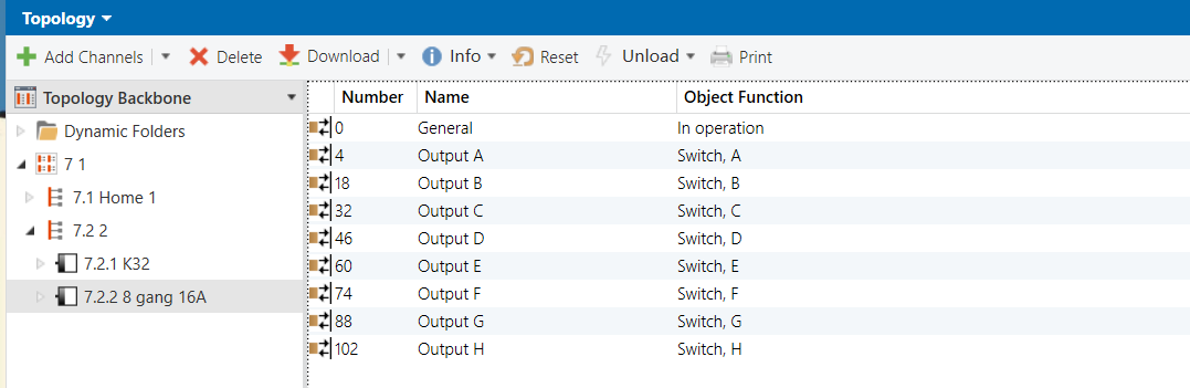
Topology
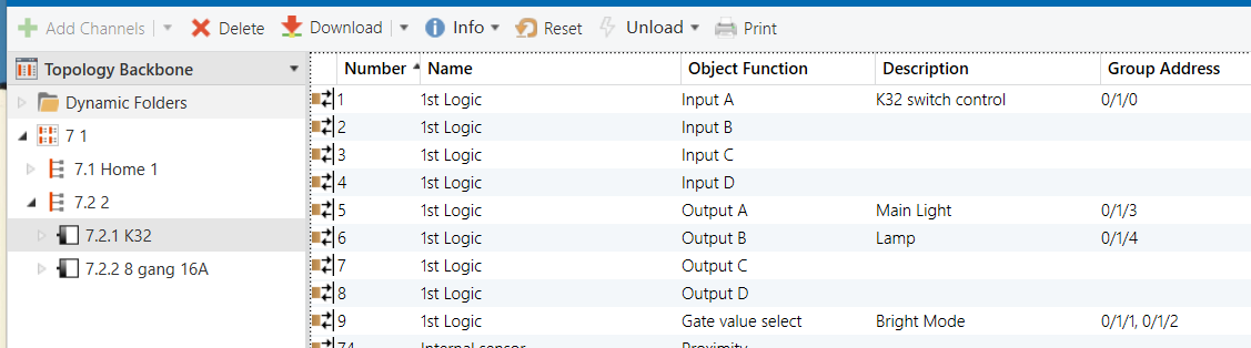
Parameters & Group Objects
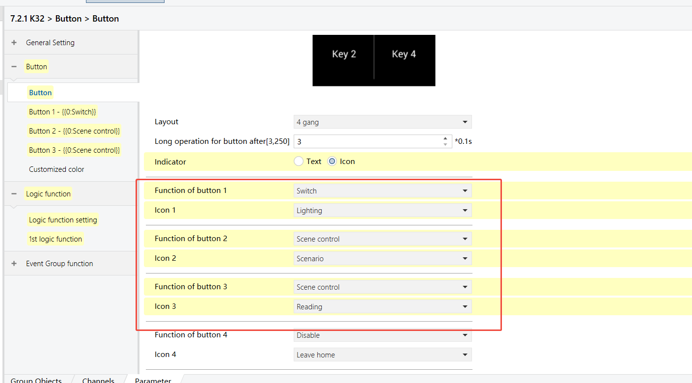
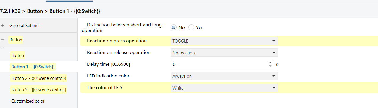
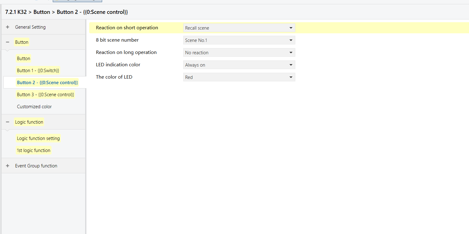
K32 - Button Function
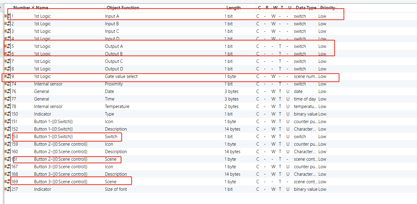
K32 - Logic Function

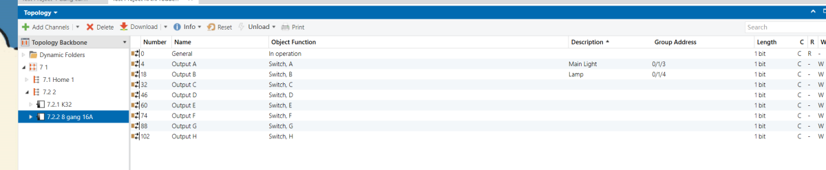
8 Gang 16A Switch Module - Outputs
Group Address Assignment
K32
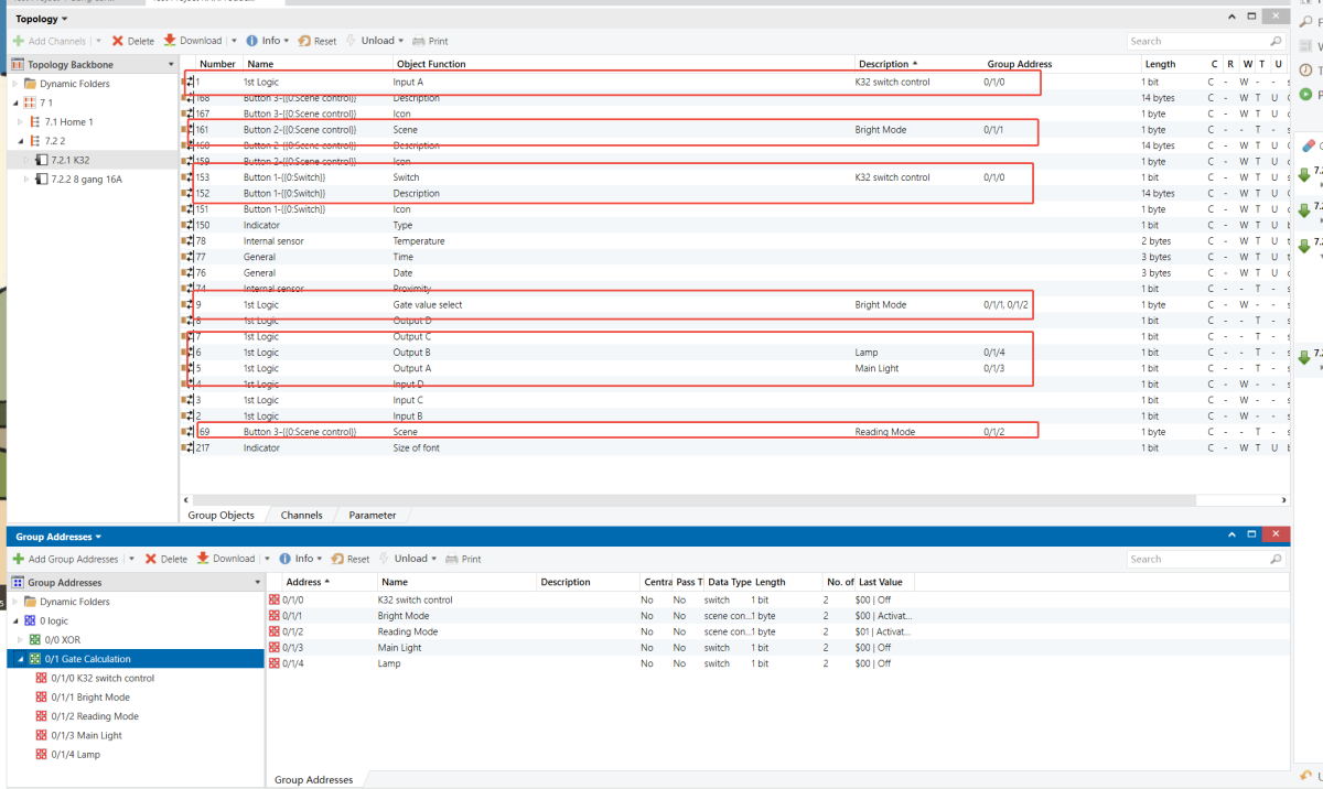
8 Gang 16A Switch Module
Threshold Comparator
Example Description
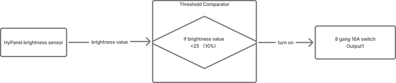
When the indoor lighting dims (brightness falls below 10%), the entrance light (Output 1 on the 8-Gang 16A switch module) turns on automatically.
Configuration Flowchart
Configuration Steps
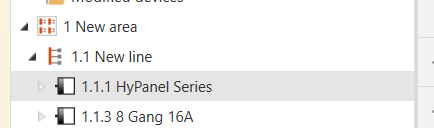
Topology
Parameters & Group Objects
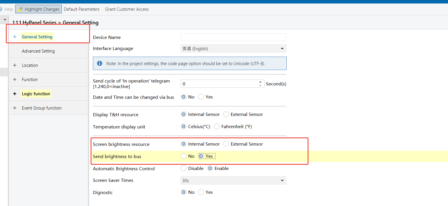
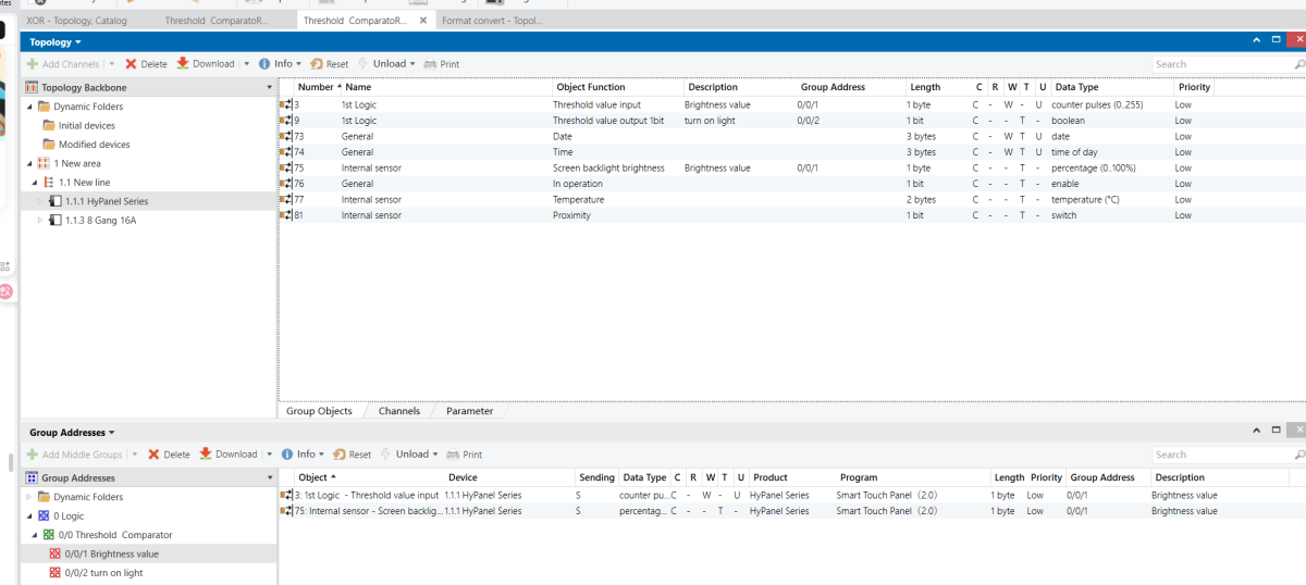
HyPanel - Brightness Sensor (enabled)
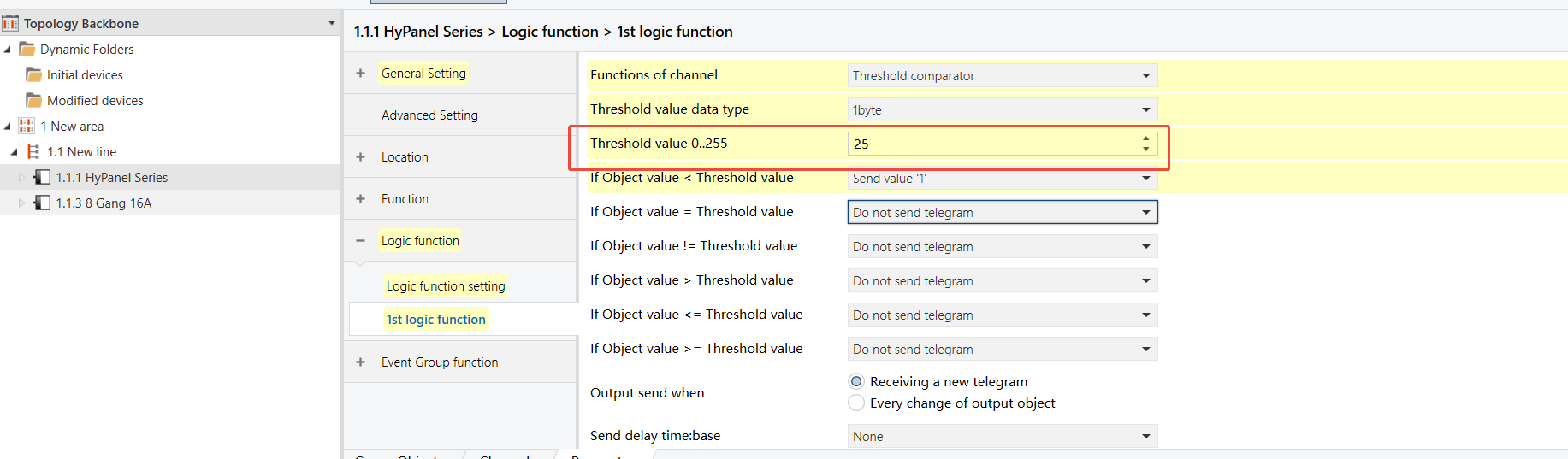
HyPanel - Threshold Comparator Logic Function
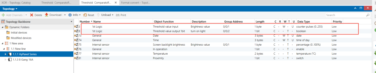
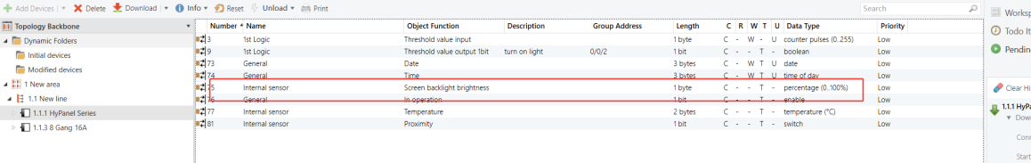
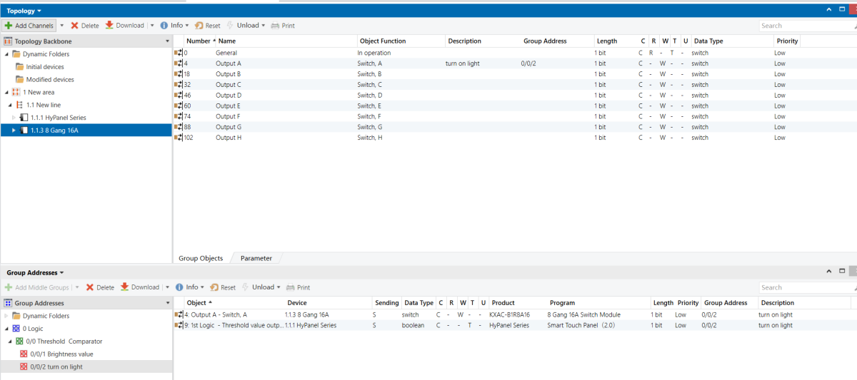
8-Gang 16A Switch Module - Group Object to be Used
Group Address Assignment
HyPanel
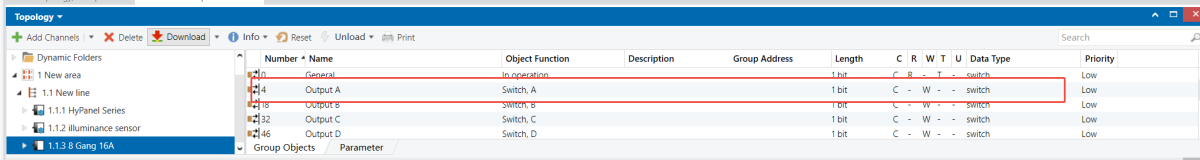
8-Gang 16A Switch Module
Format Convert
Example Description
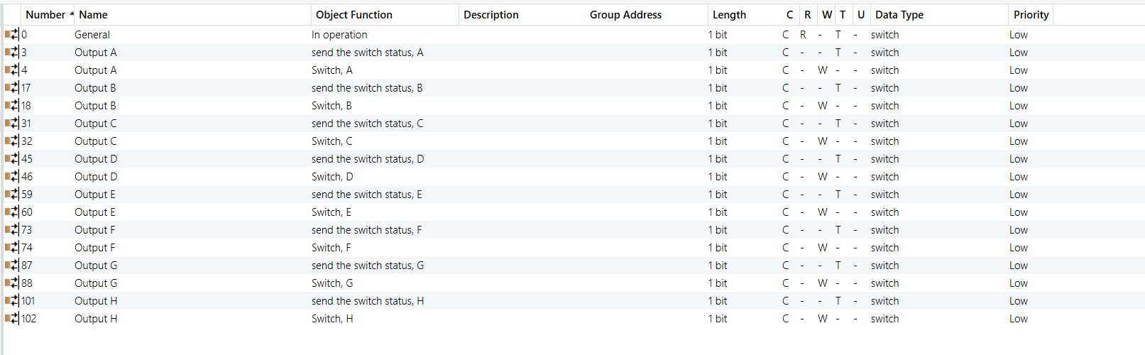
An 8-Gang 16A switch module provides eight individual1-bit switch states. It has to be connected to a third-party visualization system that can only accept a single 1-byte value to represent all switch statuses.
Configuration Flowchart
Configuration Steps
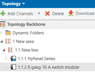
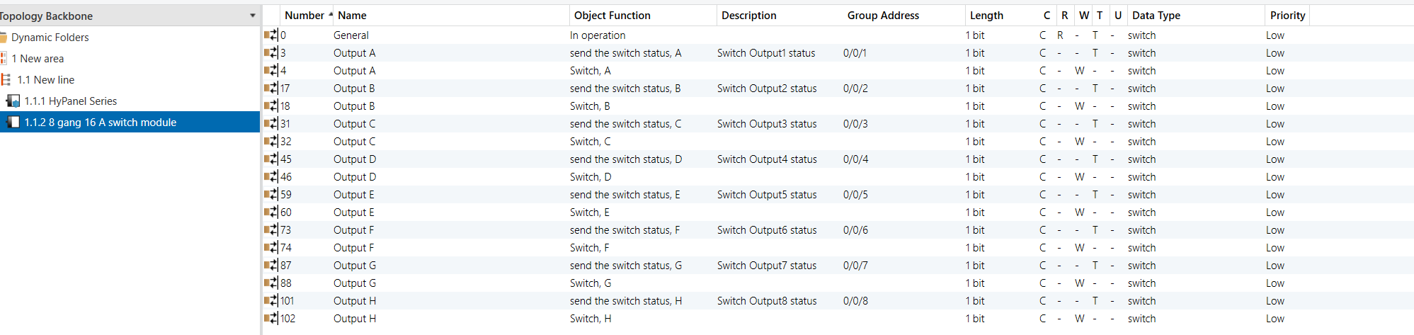
Topology
NOTE:
The visualization system database is omitted here; this example focuses on the Format Convert function itself.
Parameters & Group Objects
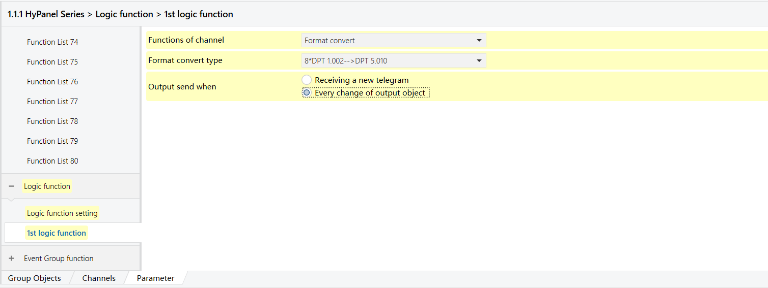
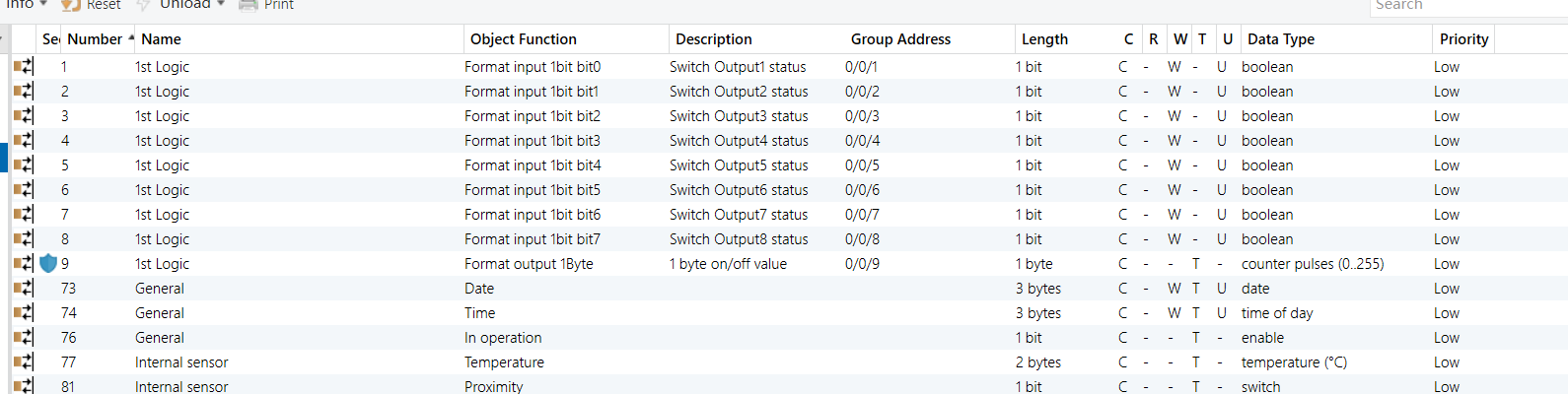
HyPanel - Format Convert Logic Function
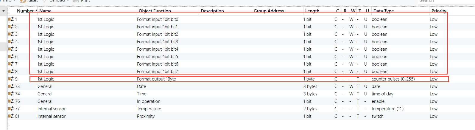
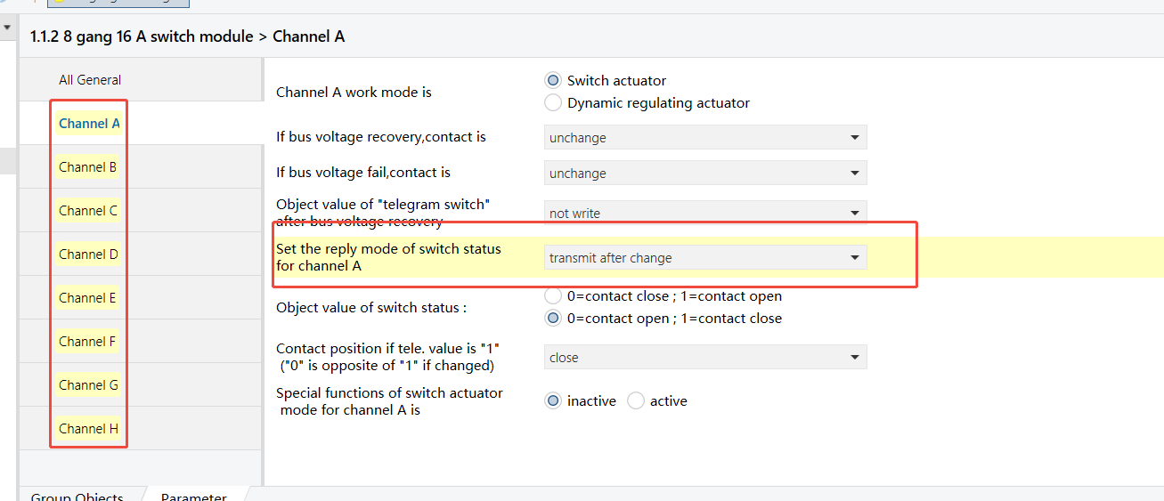
8-Gang 16A Switch Module - Status feedback enabled for each channel (Channel A shown as example)
Group Address Assignment
HyPanel
8-Gang 16A Switch Module
NOTE:
After conversion, link the resulting 1-byte on/off value to the visualization system’s input status group object so it can read the combined switch states.
Gate Calculation
Example Description
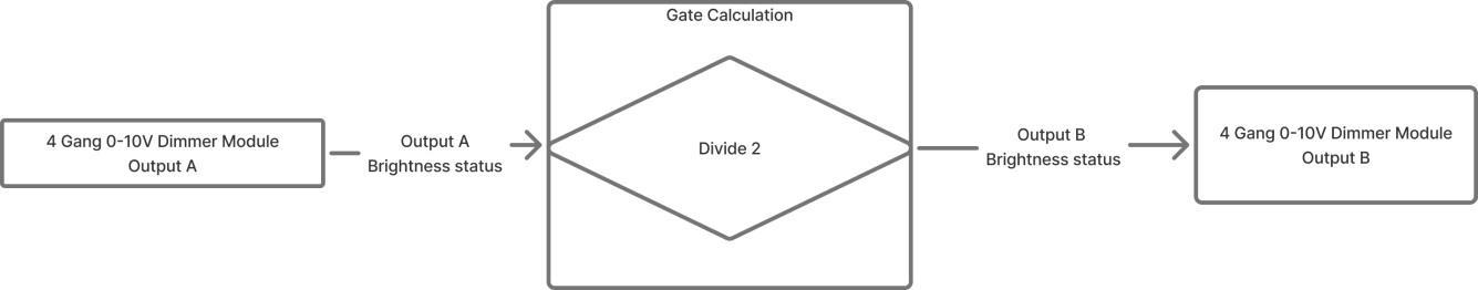
Create a lighting effect where the ambience light (Output B of 4-Gang 0-10V Dimmer Module) follows the brightness of the main light (Output A of 4-Gang 0-10V Dimmer Module), but always at 50% of the main light’s level.
Configuration Flowchart
Configuration Steps
Topology
Parameters & Group Objects
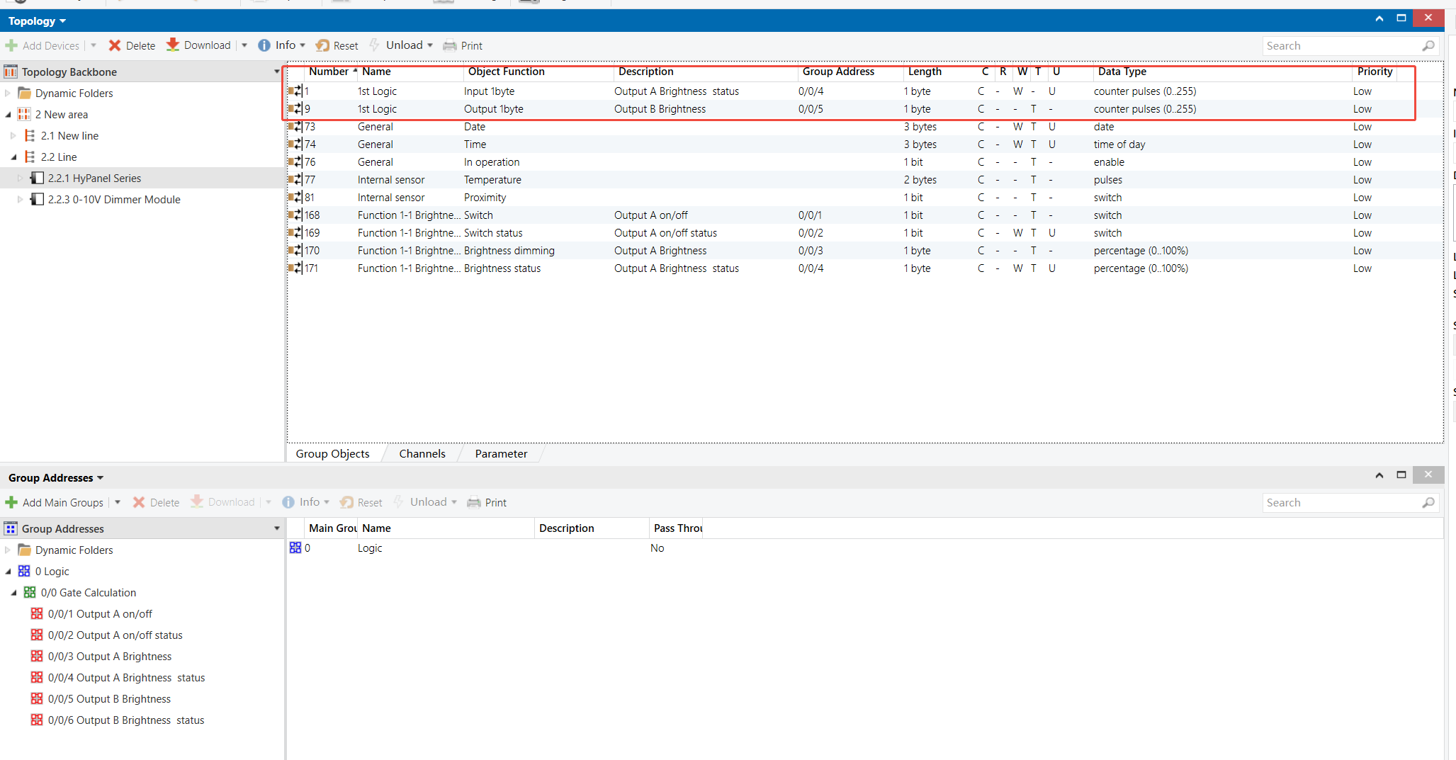
HyPanel - Gate Calculation Logic Function
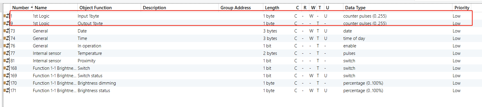
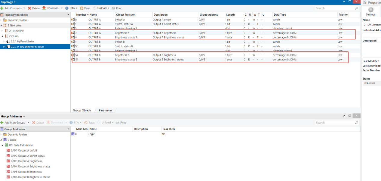
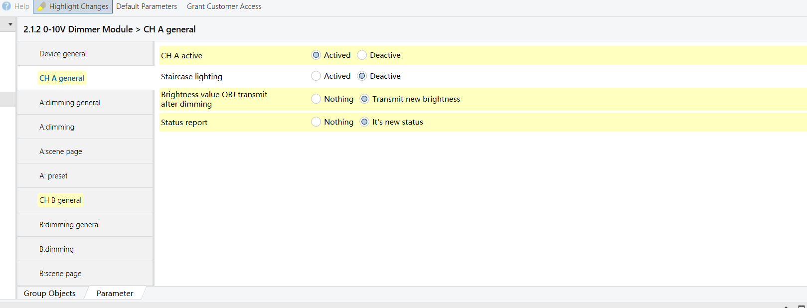
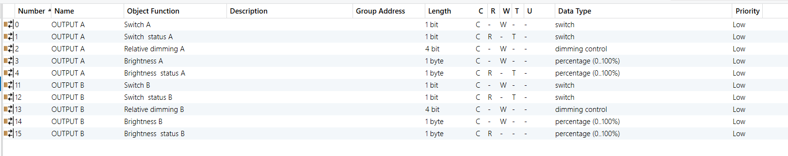
0-10V Dimmer Module - Outputs A & B (Output A as example)
Group Address Assignment