You can configure a KNX scene panel to perform dimming control for a dimmer module.
In this guide, the Aura Series K32 Button Panel (referred to as the button panel) and the 4-Gang 0-10V Dimmer Module (referred to as the dimmer module) are used as examples. The guide covers the wiring topology, ETS configuration, and basic troubleshooting.
The same configuration method applies to other KNX scene panels and dimmer modules - refer to their respective product database manuals when performing similar setups.
Overview
Wiring Topology
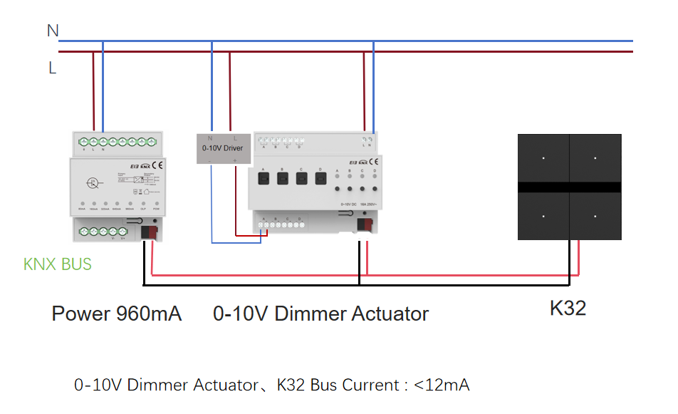
Intended Functions
Button 1 on the button panel controls Channel 1 of the dimmer module.
A short press toggles the light ON/OFF.
A long press adjusts brightness (relative dimming).
The LED indicator on Button 1 reflects the light’s current status:
Lit when the light is on.
Off when the light is off.
ETS Configuration
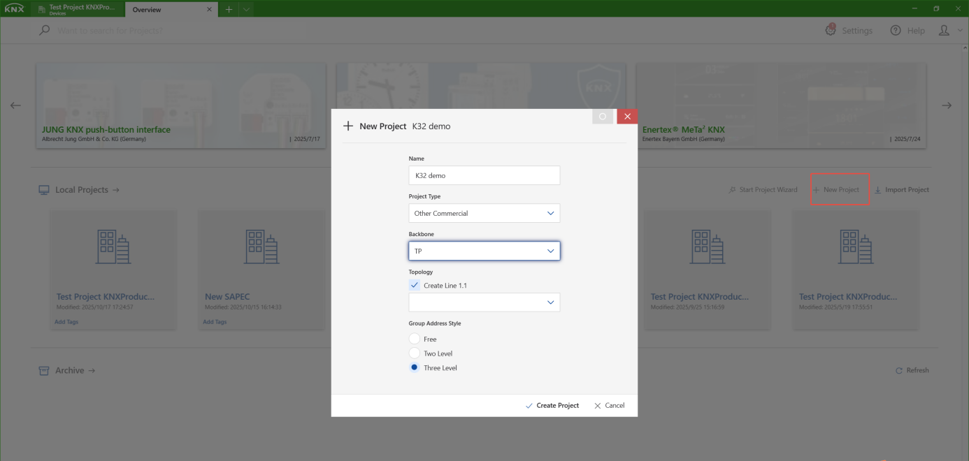
Create a Project
Open ETS and click New Project.
Enter a project name and confirm to create the project.
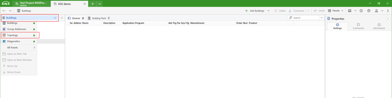
Add Devices to the Topology
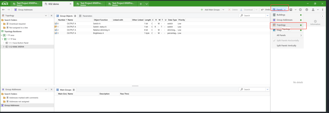
Open the project and switch to the Topology view.
Click Panels > All Panels > Catalog.
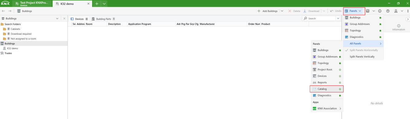
In the Catalog panel, find the button panel and dimmer module under the Akuvox manufacturer folder, then add them to the topology.
TIP:
For more detailed instructions, refer to Start a KNX Project with ETS.
Configure Device Parameters
Button Panel
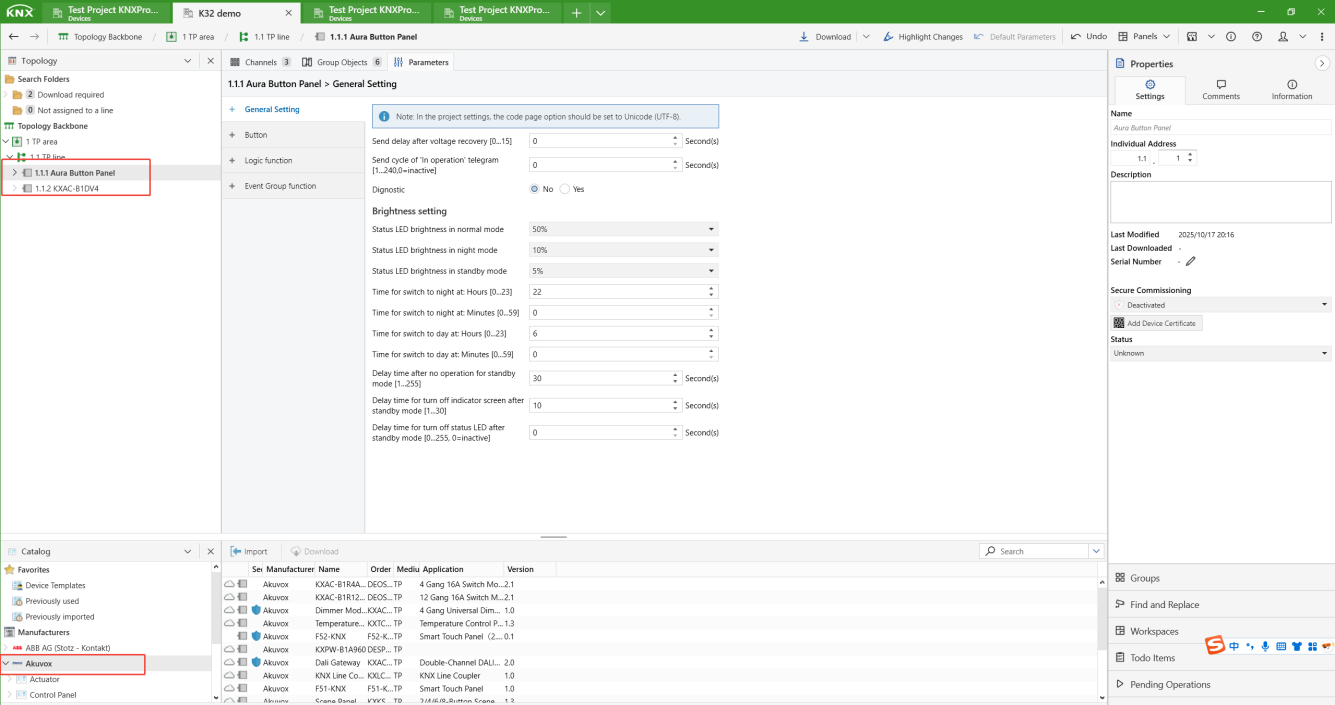
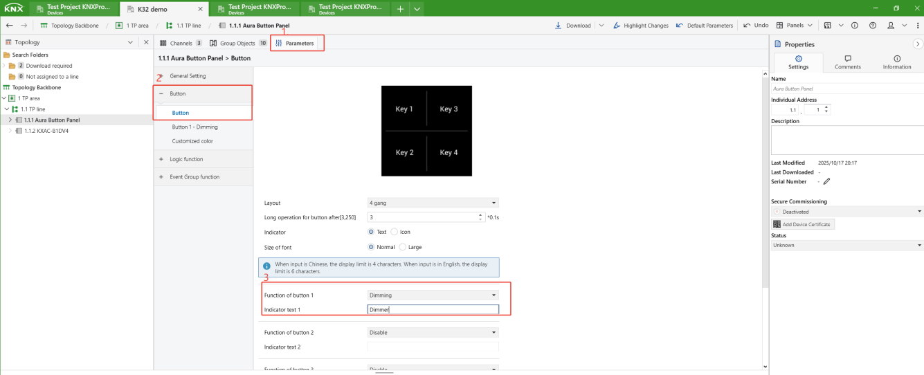
Click on the button panel in the Topology view, go to Parameters > Button, and set Function of Button 1 to Dimming.
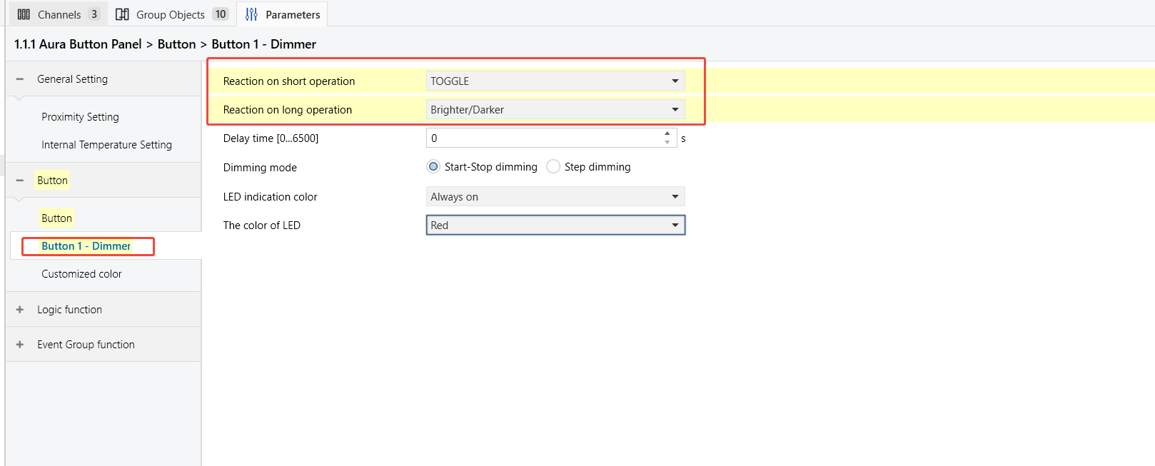
Go to the Button1 page, then:
Set Reaction on short operation to Toggle (switch control).
Set Reaction on long operation to Brighter/Darker (brightness adjustment).
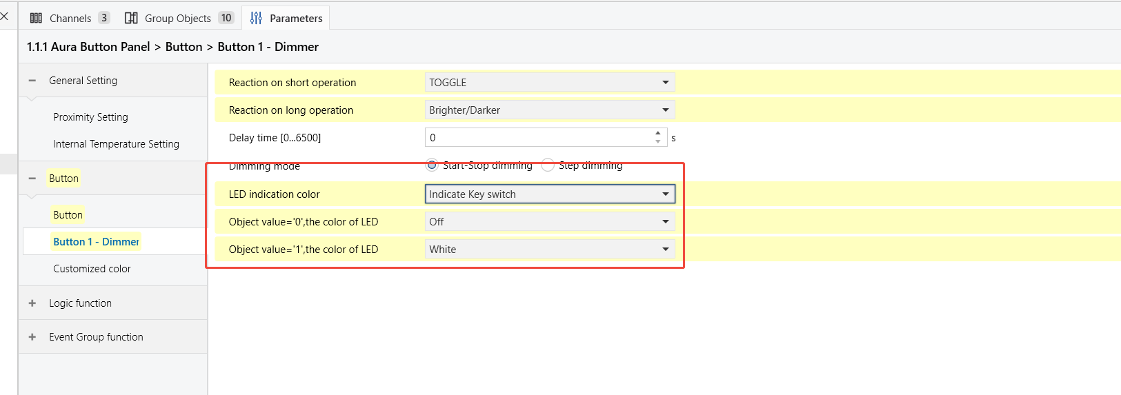
Configure the LED indicator to follow the value of the linked group object:
Set the LED indication color to Indicate Key Switch.
Set the LED color to Off when the object value is 0.
Set the LED color to White(on) when the object value is 1.
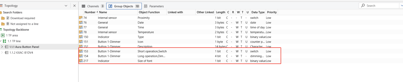
Open the Group Objects tab to view the objects that will be linked.
Dimmer Module
Click on the dimmer module on the Topology view, go to Parameters > CH A General page, then activate Channel A.
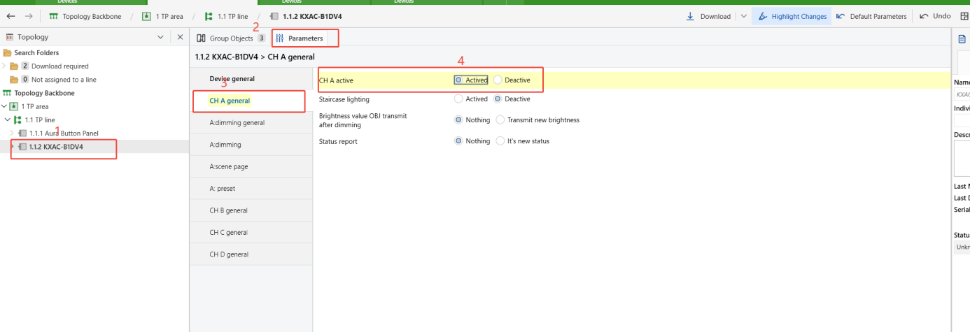
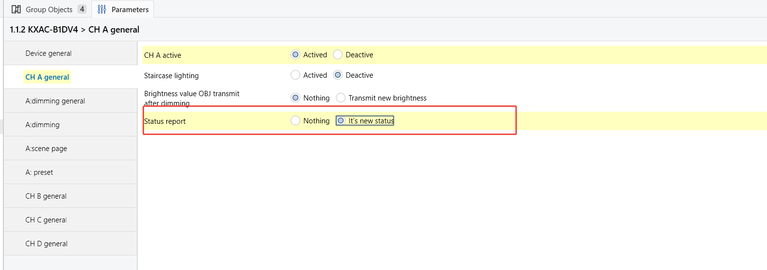
Set the Status report to It’s new status to enable the dimmer module’s switch status feedback.
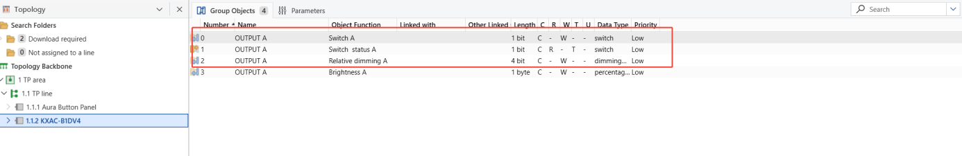
Open the Group Objects tab to view the objects that will be linked.
Create and Link Group Addresses
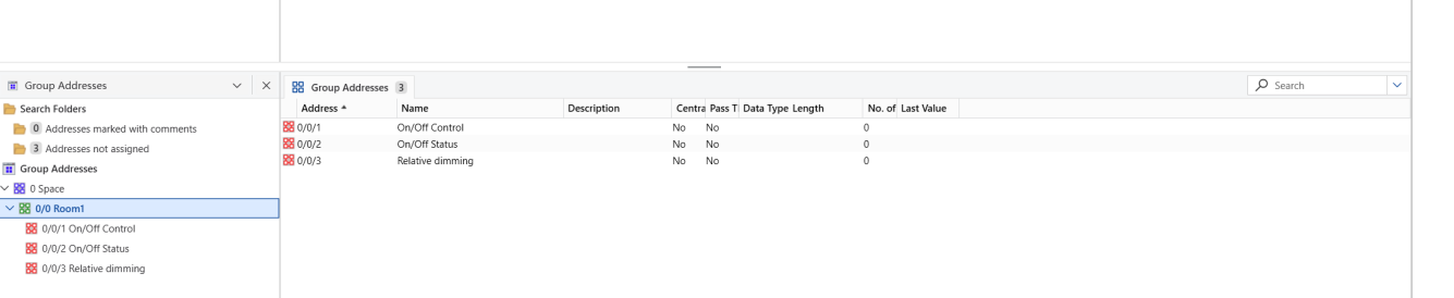
Switch to the Group Addresses view.
Create the following group addresses: On/Off Control, On/Off Status, and Relative dimming.
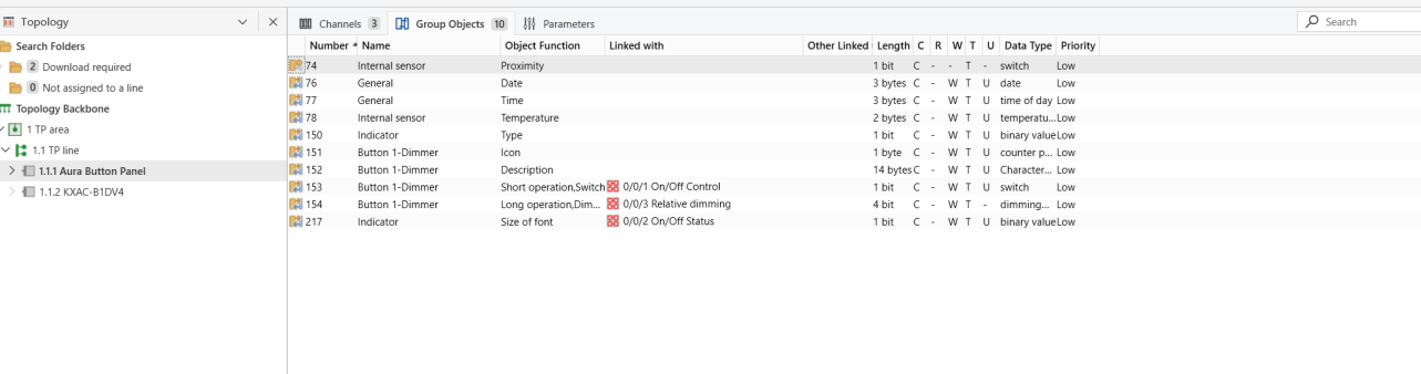
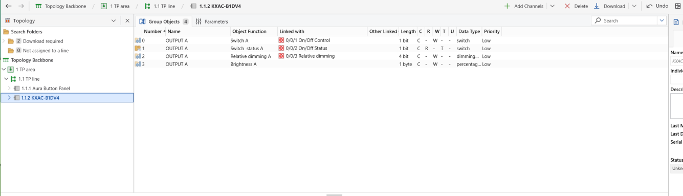
Link each group address to the appropriate group objects:
Button Panel
Dimmer Module
NOTE:
Link the Switch Status object of the dimmer module to the Indicator object of the button panel. This allows the button panel LED to reflect the light’s ON/OFF state correctly.
TIP:
For more detailed instructions, see Link Group Objects with Group AddressesLink Group Objects with Group Addresses.
Download Configuration
Follow the steps below to activate the programming mode on the devices.
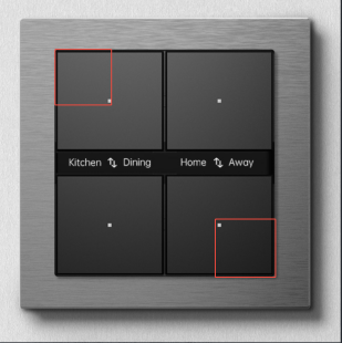
Button Panel
Press and hold the top-left and bottom-right buttons simultaneously for about 5 seconds.
The orange LED rapidly flashes 5 times, indicating that programming mode is active.
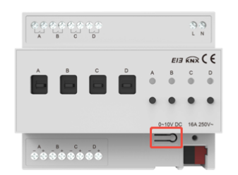
Dimmer Module
Press the button on the bottom right.
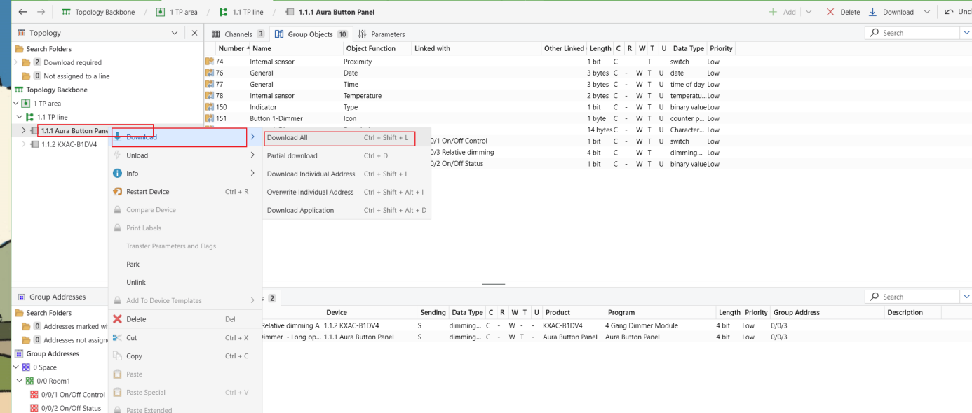
Click Download > Download All In ETS to transfer the configuration.
TIP:
For more details on KNX downloads, refer to Download Project Data to HyPanel-KNX.
Test and Troubleshooting
Function Verification
Short press and long press the button on the button panel to verify that the dimmer module responds correctly.
Check whether the button panel LED indicator synchronizes with the load device’s ON/OFF state.
Troubleshooting
If the switch control or LED indication does not work properly after downloading, follow these steps:
Check group address links
Ensure each group address is linked to at least two group objects.
Use ETS Diagnostics to monitor telegram transmission and reception for troubleshooting.
Check wiring
In ETS Diagnostics, open Device Info to confirm KNX bus wiring is normal.
Manually press the button on the dimmer module to verify that the load device operates properly.