The “Logic function setting” interface, as shown in Figure 5.8, supports the configuration of up to eight logic functions.
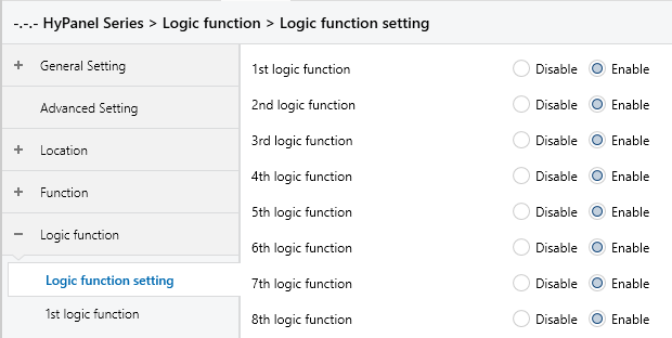
Figure 5.8: Logic function setting interface
X logic function
Sets whether to enable the logic function, as shown in Figure 5.8.
Options:
Disable
Enable: Enable and activate the corresponding logic function of channel.
Function of channel
Sets the logic function for this channel, as shown in Figure 5.8.1.
Options:
AND
OR
XOR
Gate forwarding
Threshold comparator
Format convert
Gate calculation
AND/OR/XOR: The parameters and communication objects are similar for these options, only the logical algorithm is different. The following sections will use one of the options as an example to explain the parameters.
5.8.1 AND/OR/XOR
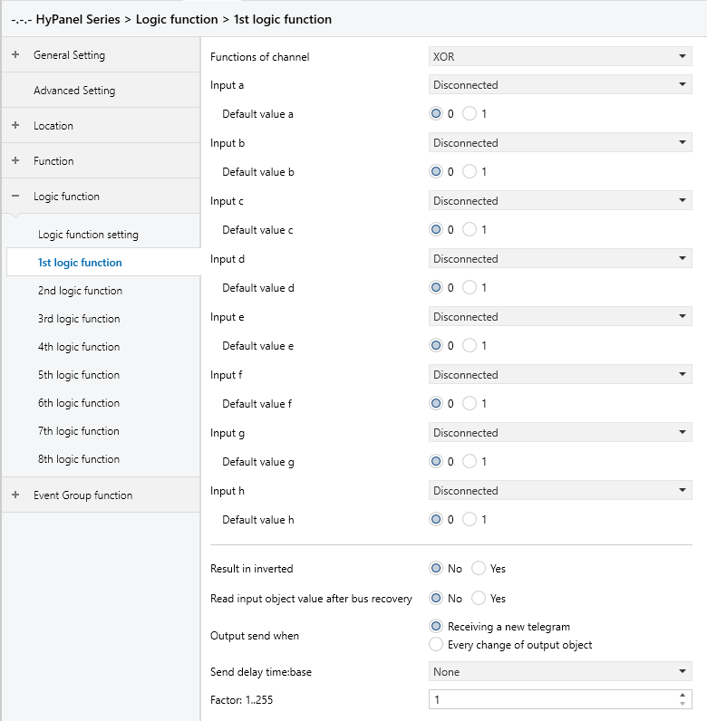
Figure 5.8.1: Logic --AND/OR/XOR interface
Input a/b/c/d/e/f/g/h
Determines whether logic input x is involved in the operation, and it is normal or inverted.
Options:
Disconnected: Not involved.
Normal: The input directly involved.
Inverted: The input is inverted before being involved.
Note:
The initial value of the input is not inverted.
Default value
Sets the initial value of the logic input x.
Options:
0
1
Result is inverted
Determines whether the logical operation result is inverted.
Options:
No: Output directly
Yes: Invert and then output
Read input object value after bus recovery
Determines whether a read request is sent to the logic input object following bus power recovery or programming.
Options:
No
Yes
Output send when
Sets the conditions for sending the logical operation result to the bus.
Options:
Receiving a new telegram: Result sent upon each reception of a new logical input value.
Every change of output object: Result sent only when it changes.
Note:
When conducting the initial logical operation, the result will be sent even if it remains unchanged.
Send delay time
Set the delay time for sending the logical operation result to the bus, calculated as Delay time = Base x Factor. If the “Base” is set to "None", there is no delay.
Base:
None
0.1s
1s
2s
5s
10s
25s
Factor: 1 .. 255
5.8.2 Gate forwarding
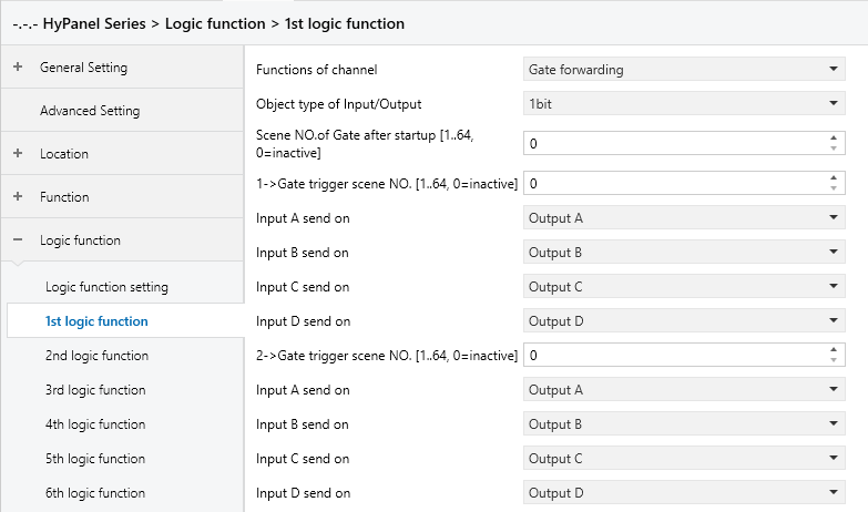
Figure 5.8.2: Logic function_Gate forwarding interface
Object type of Input/Output
Specifies the data type of the input/output.
Options:
1bit
4bit
1byte
Scene NO. of Gate after startup [1..64, 0=inactive]
Specifies the initial scene forwarded by the logic gate after device startup, which must be configured in the parameters.
Options: 1.. 64, 0 = inactive.
Tip:
It's recommended to select the gate scene before operation; otherwise, the initial scene will be activated by default.
z->Gate trigger scene NO.[1..64,0=inactive] (z:1~8)
Specifies the scene number for logic gate forwarding. Each logic can have up to 8 trigger scene settings configured.
Options: 1.. 64, 0 = inactive.
Note:
If multiple Gate trigger scene NO. values within the same Logic Function are set to the same value, the output result will follow the setting of the first Gate trigger scene NO. that meets the condition.
Input A/B/C/D send on
Sets the output of input x (x=A/B/C/D) after gate forwarding.
Options:
Output A
Output B
...
Output B, C, D
Depending on the option selected, one input can be forwarded to one or more outputs. The input value remains consistent with the the output value.
Note:
If multiple Gate trigger scene NO. values within the same Logic Function are set to the same value, the Input x send on parameters can be set to different output values.
5.8.3 Threshold comparator
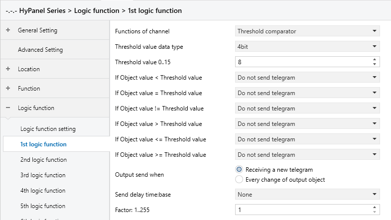
Figure 5.8.3: Logic function_Threshold comparator interface
Threshold value data byte
Sets the data type for the threshold value.
Options:
4bit: 0..15
1byte: 0..255
2byte: 0..65535
4byte: 0..4294967295
Threshold value 0..255
Sets the threshold value, which is determined by the data type.
4bit: 0 ..15
1byte: 0 .. 255
2byte: 0 .. 65535
4byte: 0 .. 4294967295
If Object value<Threshold value
If Object value=Threshold value
If Object value!=Threshold value
If Object value>Threshold value
If Object value<=Threshold value
If Object value>=Threshold value
These parameters are used to set the logic result to be sent when the input is less than, equal to, not equal to, greater than, less than or equal to, or greater than or equal to the set threshold value.
Options:
Do not send telegram: Not to select this option
Send value “0”: When the condition is met, it sends a telegram “0”.
Send value “1”: When the condition is met, it sends a telegram “1”.
Note:
In cases of conflicting options among parameters, the value to be sent will be based on the condition specified in the last parameter.
For example, if the parameter “If Object value=Threshold value" is set to "Send value 0," and parameter “If Object value<=Threshold value" is set to "Send value 1," when the object value equals the threshold value, the logic result will send the value “1”.
Output send when
Sets the conditions for sending the logical operation result to the bus.
Options:
Receiving a new telegram: Result sent upon each reception of a new logical input value.
Every change of output object: Result sent only when it changes.
Note:
When conducting the initial logical operation, the result will be sent even if it remains unchanged.
Send delay time
Set the delay time for sending the logical operation result to the bus, calculated as Delay time = Base x Factor. If the “Base” is set to "None", there is no delay.
Base:
None
0.1s
1s
2s
5s
10s
25s
Factor: 1 .. 255
5.8.4 Format convert
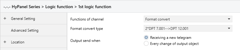
Figure 5.8.4: Logic function_Format convert interface
Format convert type
Sets the type of format conversion.
Options:
2*DPT 1.002-->DPT 2.001
8*DPT 1.002-->DPT 5.010
DPT 1.002-->DPT 5.010
DPT 5.010-->DPT 7.001
2*DPT 5.010-->DPT 7.001
2*DPT 7.001-->DPT 12.001
DPT 5.010-->8*DPT 1.002
DPT 7.001-->2*DPT 5.010
DPT 12.001-->2*DPT 7.001
DPT 232.600(RGB)-->3*DPT 5.001(%)
3*DPT 5.001(%)-->DPT 232.600(RGB)
DPT 251.600(RGBW)-->4*DPT 5.001(%)
4*DPT 5.001(%)-->DPT 251.600(RGBW)
Output send when
Defines the conditions for sending the logical operation result to the bus.
Options:
Receiving a new telegram: Result sent upon each reception of a new logical input value.
Every change of output object: Result sent only when it changes.
Note:
When conducting the initial logical operation, the result will be sent even if it remains unchanged.
5.8.5 Gate calculation
This function is mainly used to perform calculations based on input values and then output the result. This section will introduce several different calculation methods based on the Input type.
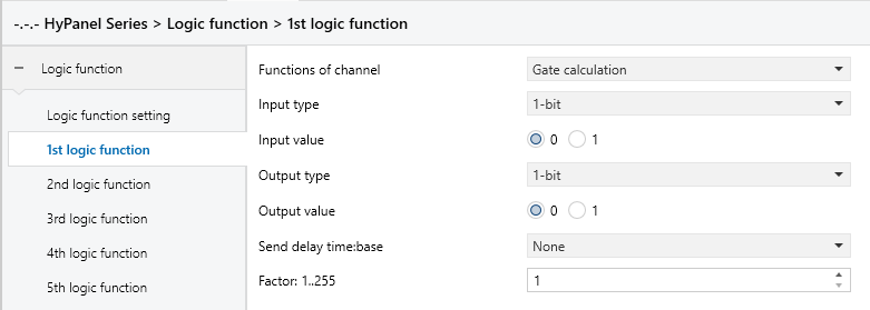
Figure 5.8.5.1: Logic function_Gate calculation_1bit interface
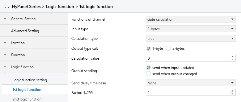
Figure 5.8.5.2: Logic function_Gate calculation_1byte interface
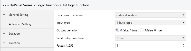
Figure 5.8.5.3: Logic function_Gate calculation_1byte logic interface
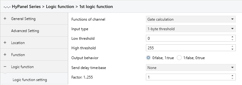
Figure 5.8.5.3: Logic function_Gate calculation_1byte threshold interface
Input type
Sets the type of input value. The calculation method and output value will vary depending on the input value type.
Options:
1-bit
2-bits
1-byte
2-bytes
1-byte logic
2-bytes logic
1-byte threshold
2-bytes threshold
Tip:
When 1-bit/2-bits is selected, the parameters can be set consistent.
When 1-byte/2-bytes is selected, the parameters can be set consistent.
When 1-bit logic/2-bits logic is selected, the parameters can be set consistent.
When 1-byte threshold/2-bytes threshold is selected, the parameters can be set consistent.
When 1-bit or 2-bits is selected for Input type, the calculation is performed by mapping the input value to a corresponding output value. The following parameters are visible:
- Input value
Sets the input value.
Options depending on the Input type object type: 0..1 / 0..3
- Output type
Defines the data type of the output.
Options:
1-bit
2-bits
1-byte
2-bytes
- Output value
Sets the output value.
Options depending on the Output type:
0..1
0..3
0..255
0..65535
When 1-byte or 2-bytes is selected for Input type, the calculation is performed based on the set input value and calculation type. The following parameters are visible:
- Calculation type
Sets the calculation type.
Options:
Disable: Disable calculation, output based on input value (see 1-bit section)
Plus: Enable Output type and Calculation value
Minus: Enable Output type and Calculation value
Multiply: Enable Output type and Calculation value
Divide: Enable Output type and Calculation value
When Disable is selected for Calculation type, the following parameters are available:
- Input value
Sets the input value.
Options depending on the Input type: 0..255/0..65535
- Output type
Defines the data type of the output.
Options:
1-bit
2-bits
1-byte
2-bytes
- Output value
This parameter sets the output value.
Options depending on the Output type:
0..1
0..3
0..255
0..65535
When Plus, Minus, Multiply, or Divide is selected for Calculation type, the following parameters are available:
- Output type
Defines the data type of the output.
Options:
1-byte
2-bytes
- Calculation value
Sets the value used for calculation.
Options depending on the Output type:
0..255
0..65535
Tip:
When "Plus" is selected for the Calculation type, the values will be added.
When "Minus" is selected for the Calculation type, the values will be subtracted.
When "Multiply" is selected for the Calculation type, the values will be multiplied.
When "Divide" is selected for the Calculation type, the values will be divided.
- Output sending
Sets the sending condition for the calculation result.
Options:
Send when input updated: Sends result to the bus whenever a new input is received.
Send when output changed: Sends result to the bus only when the output changes.
When 1-byte logic or 2-bytes logic is selected for Input type, the calculation method based on whether the input value is zero and then outputs True or False accordingly. The following parameters are available:
- Output behavior
Defines the output behavior for True and False.
Options:
0:false, 1:true
1:false, 0:true
When 1-byte threshold or 2-bytes threshold is selected for Input type, the calculation method based on whether the input value is zero and then outputs True or False accordingly. The following parameters are available:
- Low threshold
Sets the minimum threshold.
Options depending on Input type: 0..255 / 0..65535
- High threshold
Sets the maximum threshold.
Options depending on Input type: 0..255 / 0..65535
- Output behavior
Defines the output behavior for True and False.
Options:
0:false, 1:true: When the value is outside the defined range, the result is 0:false; when within the range, the result is 1:true.
1:false, 0:true: When the value is outside the defined range, the result is 1:false; when within the range, the result is 0:true.
Send delay time
Specifies the delay time for sending the logical operation result to the bus, calculated as Delay time = Base x Factor. If the “Base” is set to "None", there is no delay.
Base:
None
0.1s
1s
2s
5s
10s
25s
Factor: 1 .. 255