LED11 is an external visual and audible indicator device that connects to Akuvox indoor monitors via RS485 interface. It is used to provide real-time status feedback such as alarm events and system disarm states through LED signals and optional buzzer alerts.
By integrating LED11 with the indoor monitor, the system can deliver enhanced visual and audio notifications for security-related events, improving situational awareness in residential or commercial environments.
This guide explains how to wire, configure, and control LED11 using both local device settings and HTTP API commands.
Before You Start
Before installing and configuring LED11, ensure the following requirements are met to guarantee stable RS485 communication and proper device operation.
Prerequisites
The indoor monitor must support the LED11 external relay function via the RS485 interface.
Device firmware must meet the minimum version listed in the compatibility table.
A stable 12V DC power supply is required for LED11.
RS485 wiring must follow the correct polarity (A/B) between LED11 and the indoor monitor.
Ensure the device is powered off before wiring installation to avoid electrical damage.
Wiring
Please refer to the wiring diagram below for the correct connection.
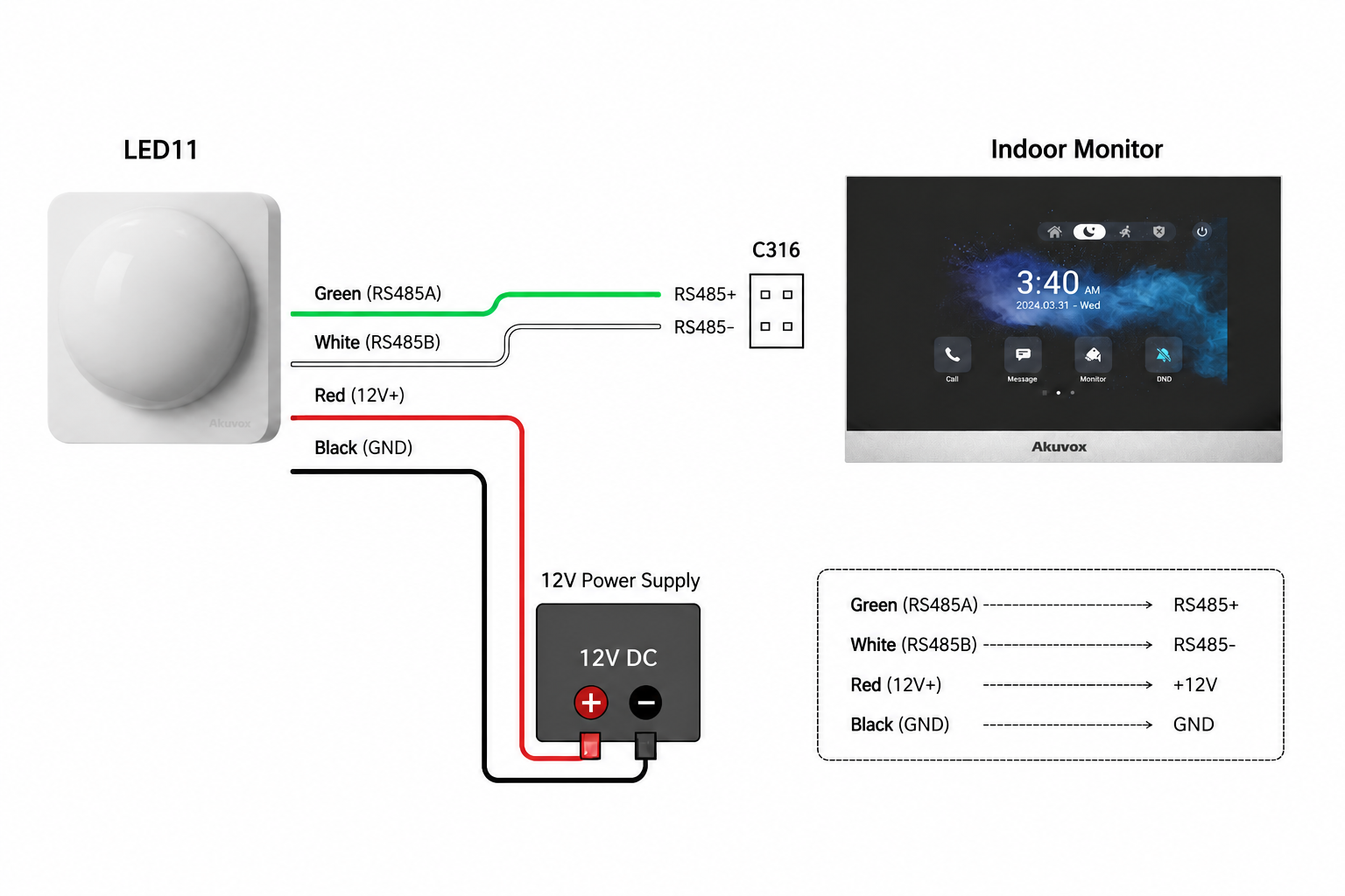
Note
LED11 is a low-voltage device and must only be powered by a regulated 12V DC supply.
Do not connect LED11 directly to AC power sources.
Ensure all wiring connections are secure before powering on the system.
Compatible Models and Minimum Firmware Version
Model | Minimum Version |
|---|---|
C316 | 316.30.15.203 |
IT88 | 88.30.15.201 |
S562 | 562.30.16.144 |
S563 | 563.30.15.207 |
This article uses C316 as an example.
Configuration
Navigate to the device IP in a browser. Log in with the default credentials (admin/admin) unless they have been changed.
Go to Device > External Relay.
Set Type to LED11.
Enable LED11 status for event types:
Alarm Triggered
System Disarmed
Configure LED behavior settings such as Light, Color, Light Mode, and Buzzer according to requirements.
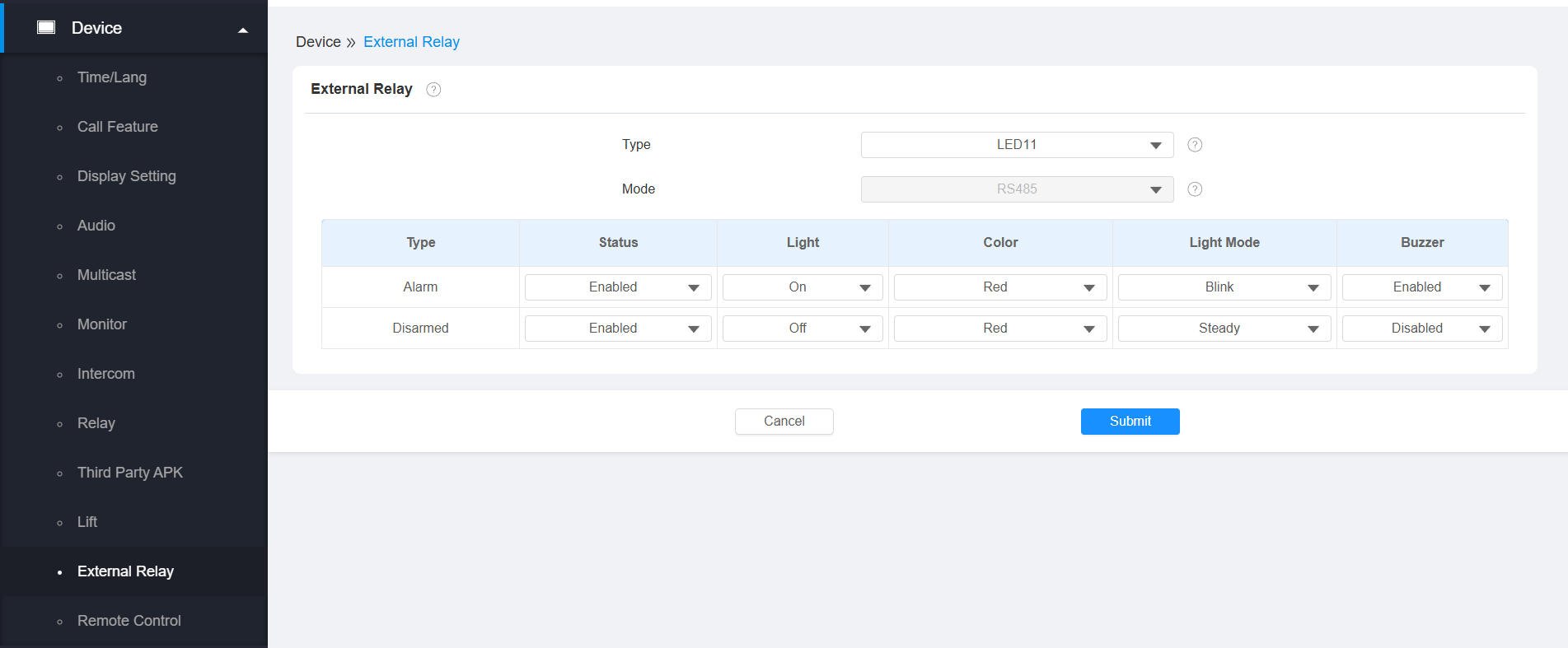
Click Submit.
API Configuration (Remote Control)
After enabling the API feature, the indoor monitor allows external systems to trigger LED status changes and buzzer actions through HTTP requests.
Go to Security > API.
Enable the API feature.
Select the required authentication mode.
Set API username and password.
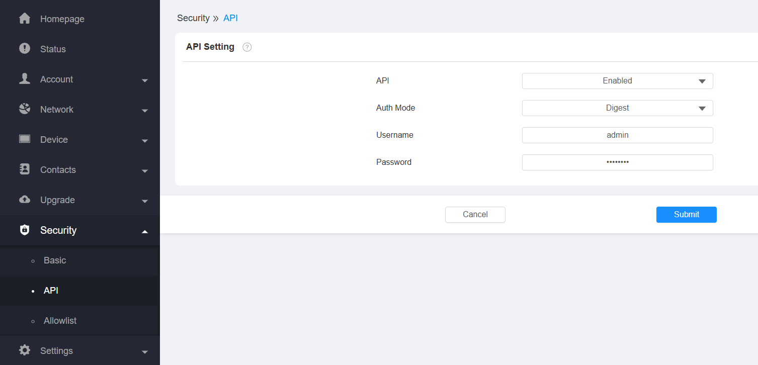
Click Submit.
API Command Example
Base URL:
https://{device_ip}/api/thirdpart/led11_control
Example Request:
https://192.168.31.187/api/thirdpart/led11_control?address=0&color=red&mode=blink&onMs=500&offMs=500&buzzerMode=off&buzzerOnMs=500&buzzerOffMs=500
Parameters
Parameter | Description |
|---|---|
device_ip | IP address of the indoor monitor |
color | LED color (red, green, blue, yellow) |
mode | LED mode: off, steady, blink |
onMs / offMs | ON/OFF duration in milliseconds for blink mode |
buzzerMode | Enable or disable the buzzer (on/off) |
buzzerOnMs / buzzerOffMs | Buzzer ON/OFF duration in milliseconds |
Verification
When an alarm is triggered or the system is disarmed, LED11 will respond with the configured light effect and/or buzzer sound.
Troubleshooting
LED11 does not respond: Check RS485 polarity and wiring connection.
No LED output: Verify LED11 is enabled in External Relay settings.
API command fails: Ensure the API is enabled and authentication is correct.
Incorrect behavior: Confirm the firmware version meets minimum requirements.