Some Akuvox door phones and access control terminals can provide power for external relays.
Please refer to the charts for specifications.
Door Phones
Model | Independent Port for External Power Supply | Power Supply via Relay | Maximum Volts/Currents | Requirements |
|---|---|---|---|---|
X910 | x | ✔ | 12V/600mA | The device should be powered by a PoE+. |
X916S | X | ✔ | 12V/500mA | The device should be powered by a DC power connector with input not less than 24V/2.5A. |
X915S V1/V2 | X | ✔ | 12V/1A | The device should be powered by a DC power connector with input not less than 24V/2.5A. |
X915 V2 | X | ✔ | 12V/1A | When the device’s hardware version is 2915.1.0.8 ~ 2915.1.0.13 and the firmware version is 2915.30.10.228 or higher, it can be powered by PoE. |
X912S | X | ✔ | 12V/1A | The device can be powered by a PoE+ or DC power connector with input not less than 12V/2.5A. |
X912K | X | ✔ | 12V/1A | |
S539 | X | ✔ | 12V/1A | The device should be powered by a DC power connector with input not less than 24V/2.5A. |
S538 | X | ✔ | 12V/500mA | The device can be powered by a PoE+ or DC power connector with input not less than 24V/1.5A. Cold-resistant version of S538: the external power supply requirement is DC input only, with an input rating of no less than 24V/2A. |
S535 | X | ✔ | 12V/1A | The device can be powered by a PoE+ or DC power connector with input not less than 12V/2A. |
S532 | X | ✔ | 12V/500mA | The device should be powered by a DC power connector with input not less than 12V/2.5A. |
R29 V1.1 | X | ✔ | 12V/500mA | The device can be powered by a PoE+ or DC power connector with input not less than 12V/2A. |
R29 V1.0 | X | X | X | X |
R28 | ✔ | X | 12V/400mA | Powered by a DC power connector or PoE. |
R27 | ✔ | X | 12V/400mA | Powered by a DC power connector or PoE(The device cannot provide power when the heating function is enabled). |
R20K V3.0 | X | ✔ | 12V/500mA | The device should be powered by a DC power connector with input not less than 12V/1.2A, or PoE. To be powered by PoE, the device firmware version should be 320.30.11.42 or higher, and the power supply is affected by the device’s volume adjustment. |
R20K V2.0 | X | X | X | X |
R20B V2.0 | X | ✔ | 12V/500mA | The device should be powered by a DC power connector with input not less than 12V/1.2A, or PoE. To be powered by PoE, the device firmware version should be 320.30.11.42 or higher, and the power supply is affected by the device’s volume adjustment. |
R20B V1.0 | X | X | X | X |
R20A V5.0 | X | ✔ | 12V/500mA | The device should be powered by a DC power connector with input not less than 12V/1.2A, or PoE. To be powered by PoE, the device firmware version should be 320.30.11.42 or higher, and the power supply is affected by the device’s volume adjustment. |
R25 Series | x | ✔ | 12V/400mA | Powered by a DC power connector or PoE. To be powered by PoE, the device firmware version should be 25.30.10.11 or higher, and the power supply is affected by the device’s volume adjustment. |
R20A V3.0 | X | X | X | X |
E21A/E21V | X | X | X | X |
E20S | X | X | X | X |
E18C | X | X | X | X |
E16C | X | X | X | X |
E12S/E12W | X | X | X | X |
DB01 | X | X | X | X |
Access Control Terminals
Model | Independent Port(S) for External Power Supply | Power Supply via Relay | Maximum Volts/Currents | Requirements |
|---|---|---|---|---|
A094 | ✔,4 ports | X | 12V/800mA | The device should be powered by an AC power connector with input not less than 100- 240VAC/1.5A (used simultaneously for 4 external power supplies) |
A095 | ✔, 8 ports | X | 12V/500mA |
|
A08 | X | ✔ | 12V/500mA |
|
A05 | X | X | X | X |
A03/02/01 | X | ✔ | 12V/500mA | The device can be powered by PoE or a DC power connector with input not less than 12V/1A |
Wiring
The wiring varies by device interface. For devices like R28 that have an independent interface for power output, simply connect the external device to its power output and GND interfaces.
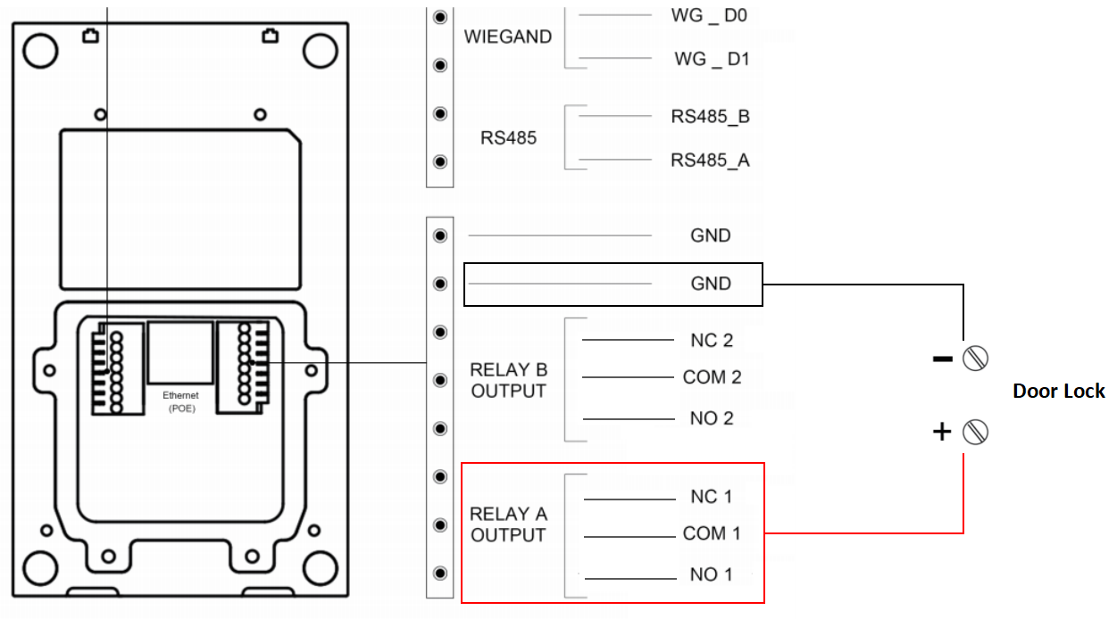
For other devices, generally, use RelayA’s NO, COM, NC, and any GND for connection. Select the wiring method based on the device’s usage.
Take the connection with an electronic lock as an example.
For Normally Closed (NC) Locks:
Connect GND and NC (same as GND and COM).
By default, the device supplies power to the lock that is locked. The lock opens when the power is cut off.
For Normally Open (NO) Locks:
Connect GND and NO.
By default, the device does not supply power to the lock that is locked. The lock opens when it is powered.
For Relay-Controlled Boards:
Connect GND and NC.
By default, the device does not supply power to the lock that is locked. The board controls its relay to open when it is powered.
R20A Interface
Configuration
To use the 12V Power Output feature, set it up on the device’s web interface.
Take the access control terminal A094 as an example.
Use the device IP to log in to its web interface. The default username and password are admin.
Go to Access Control > Relay > 12V Power Output interface.
Select the power output type.
Always:
It is generally for the GND and NC connection.
The device provides a continuous power supply.
Upon triggering, the relay switches from NC to NO, cutting off the power.
Power is restored after the relay is reset.
Triggered by Open Relay:
It is generally for the GND and NO connection.
After triggering, the relay switches from NO to NC, initiating the power supply.
The power supply is cut off after the relay is reset.
The relay can be reset automatically after the pre-selected timeout(3, 5, or 10 seconds).
