This guide applies to akubela Cloud version 3.2.0 and all versions of ETS5 and ETS6. It covers how to create KNX programs and scenes in the ETS software, as well as how to integrate ZigBee devices into a KNX system.
Floor Plan and Device Selection Example
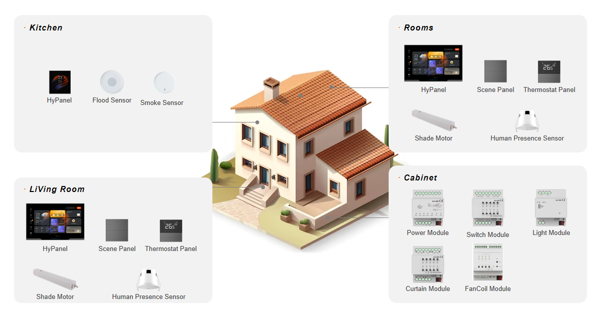
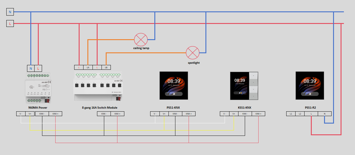
We will use the floor plan and devices shown in the image below to guide you through the project creation process.
Device placement locations: Entryway, kitchen, dining room, living room, home office, and bedrooms.
Device types: Switches, lighting devices, thermostats, curtains, and security devices.
Communication protocol: KNX, Zigbee.
Before Getting Started
1. Understand Customer Requirements
Clarify the customer's expectations and functional needs for their smart home system.
2. Design Scenes
Plan scenes based on different areas and usage scenarios:
Area | Scene |
Kitchen | Cooking, Leave Kitchen |
Living Room | Movie Time, Relaxation, Hosting Guests, Leave Room |
Bedroom | Reading, Night, Sleep, Soft Lighting |
Entryway | Welcome Home, Leave Home |
3. Collect Device Models and MAC Addresses
To proceed with the project setup, collect the necessary device information:
Device models: Found on the label of the packaging or device panel.
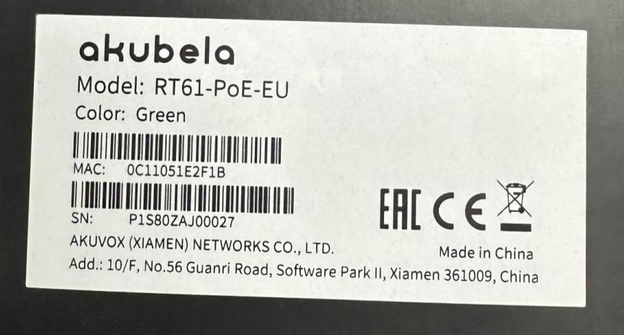
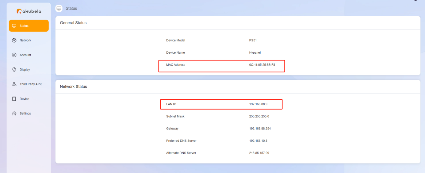
MAC and IP Address: Can be viewed via the device's web interface.
TIP:
You can use the following table format for device information collection.
Device
Model
IP address
MAC address
HyPanel
PS51-KNX-EU
192.168.88.9
MAC1
HyPanel
PS51-R2-EU
192.168.88.10
MAC2
HyPanel Lite
KS41-KNX-EU
192.168.88.11
MAC3
4. Update Devices
4.1. Collect device firmware versions
Use the following table format to record firmware versions:
Device | Current Version | Latest Version |
HyPanel | 51.1.36.417 | View and download the latest firmware from the Knowledge Base |
HyPanel | 51.1.36.417 | |
HyPanel lite | 41.1.36.55 |
4.2. Update device firmware
Update the devices on the cloud by following the guide.
5. Obtain ETS Database
There are two ways to obtain the ETS database:
Download from the ETS product catalog.
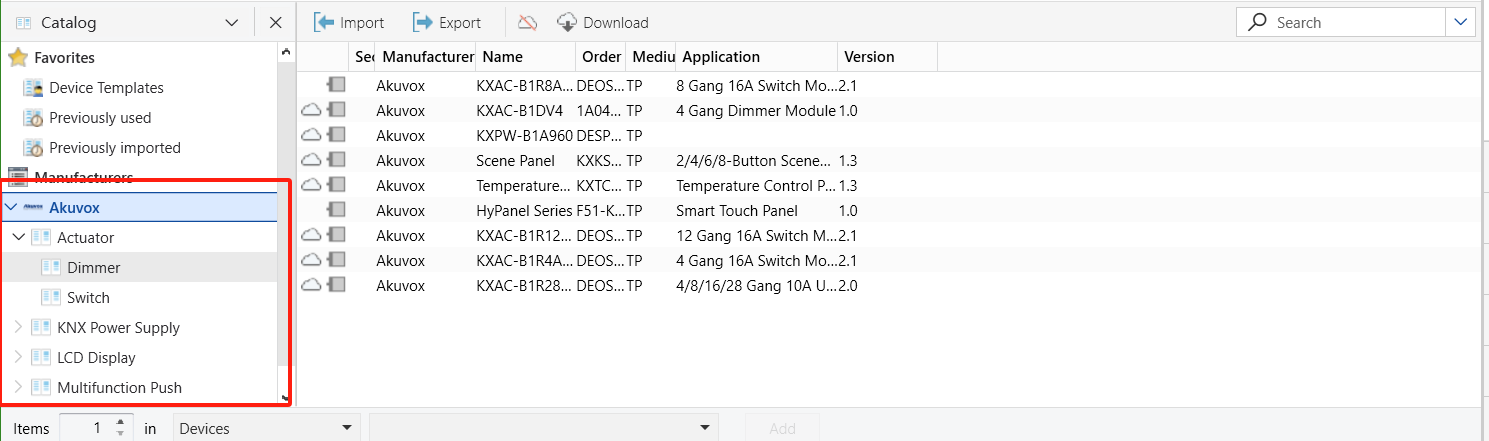
Copy from another project.
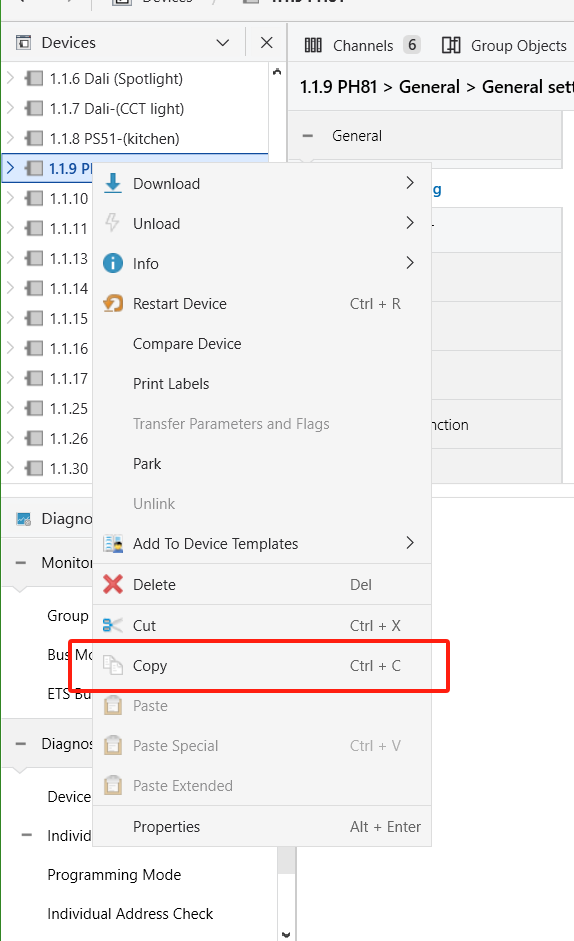
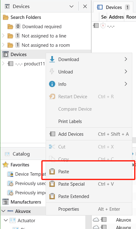
For detailed instructions, refer to this guide.
Installation and Configuration
1. Connect KNX Devices to Power and Internet
1.1. Power on devices
1.2 Connect devices to the Internet
Refer to the instructions below to connect HyPanel-KNX devices to the internet.
Device | Operation |
HyPanel (PS51-KNX-EU) | Use an Ethernet cable |
HyPanel Lite (KS41-KNX-EU) | Use an Ethernet cable |
2. Power On and Put ZigBee Devices into Pairing Mode
Refer to the instructions below to power on devices and enter pairing mode. For other devices, see this guide or their user manuals for detailed guidance.
2.1. Power on devices
Device | Operation |
|---|---|
Flood Sensor | Powered by CR2032 battery |
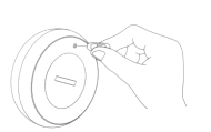
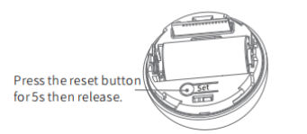
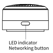
2.2. Put devices in pairing mode
Device | Enter Pairing Mode |
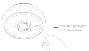
Flood Sensor | 1. Rotate the battery cover counterclockwise to open it. 2. Press and hold the reset button for 5–10 seconds until the green light flashes rapidly. |
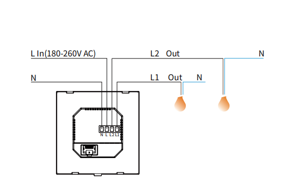
3. Connect High-Voltage Devices to Power and Internet
Refer to the instructions below to connect the relay version HyPanel to the power and internet.
3.1. Power on devices
Device | Operation |
HyPanel(PS51-R2-EU) |
|
3.2. Connect devices to the Internet
Device | Operation |
HyPanel(PS51-R2-EU) | Use an Ethernet cable or connect to Wi-Fi |
4. Connect Devices to the Cloud
4.1. Connect HyPanel devices to the cloud
(1) On the akubela Cloud, go to Project > Single-tenant > Detail > Install to view the installation code required for cloud connection.
(2) Export the installation code for use during the device’s initial setup.
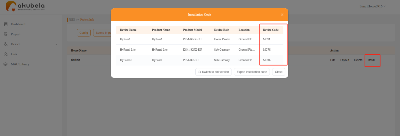
(3) During the initial setup, enter the installation code to connect the device to the cloud.
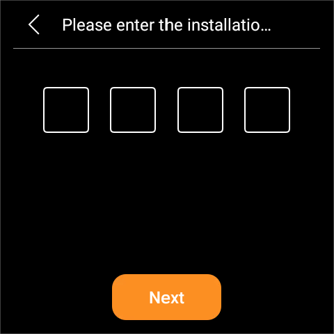
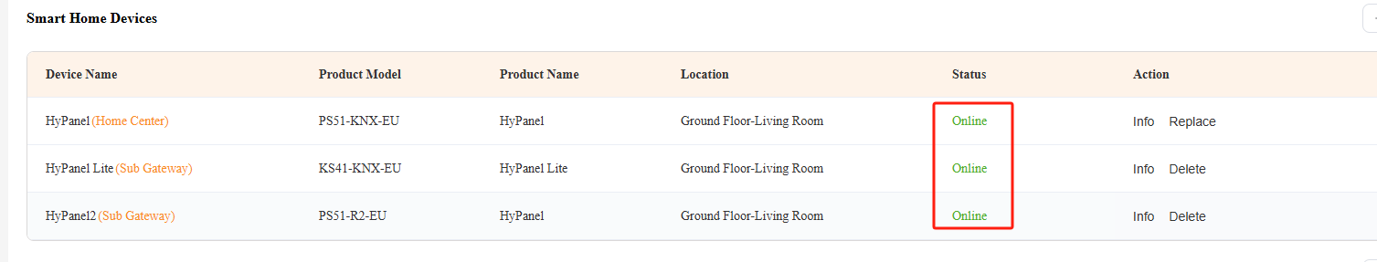
Once connected, the device status will change to be Online.
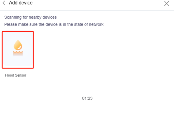
4.2. Add ZigBee Devices
HyPanel can connect to various ZigBee devices, including sensors, emergency buttons, IR controllers, thermostats, smart switches, and more.
Let's take the flood sensor as an example.
(1) Put devices into pairing mode
Before pairing ZigBee devices with HyPanel, you should know how to put them into pairing mode. Here are some examples to guide you.
TIP:
For more instructions on pairing other devices, check our guide on Put ZigBee Devices into Paring Mode.
ZigBee Device | Put it to Pairing Mode | |
Smart Emergency Button
| Insert a pin into the reset hole at its back cover for at least 5s until the green light flashes quickly. |
|
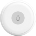
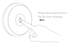
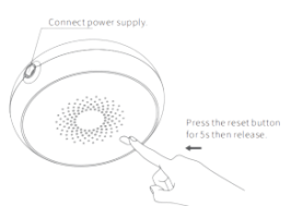
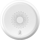
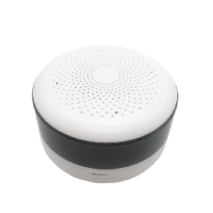
Smart Flood Sensor
| Press and hold the reset button on the front for at least 5s until the green light flashes quickly. |
|
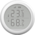
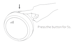
Smart Temperature and Humidity sensor
| Press and hold the reset button on the side for at least 5 s until the signal icon flashes quickly. |
|
Smart Motion Sensor
| 1. Rotate the battery cover anticlockwise to open. 2. Press and hold the reset button for at least 5s until the green light flashes quickly. |
|
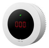
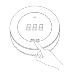
Smart Gas Sensor
| Press and hold the reset button on the front for at least 5s until the green light flashes quickly. |
|
Smart Smoke Sensor
| Press and hold the reset button on the front for at least 5s until the green light flashes quickly. |
|
Smart CO Sensor
|
|
|
IR Controller
|
|
|

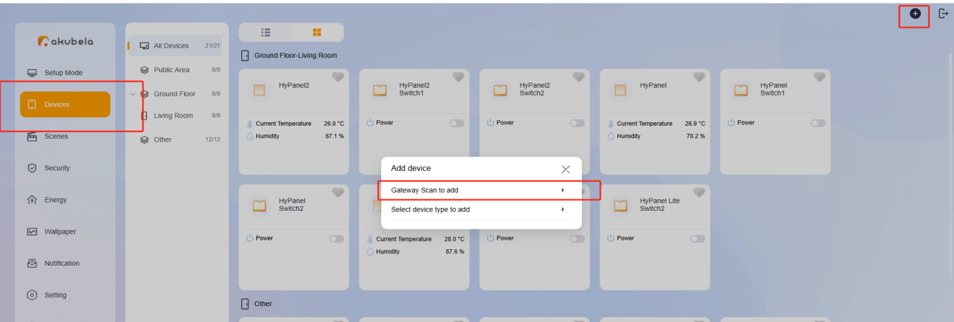
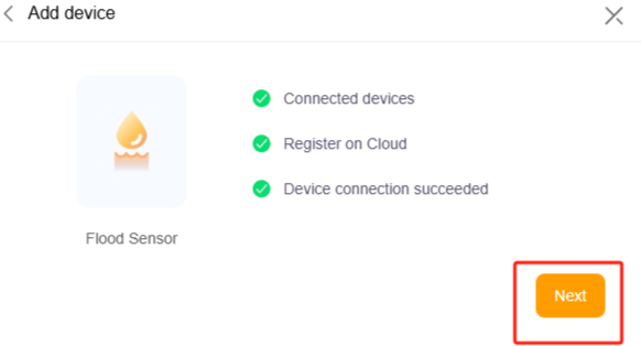
(2) Add Zigbee devices to the system
① Log into the device web portal(default username and password: admin).
② Go to Devices, click “+” in the top right corner, and select Gateway Scan to add.
③ Choose the desired HyPanel device from the list.
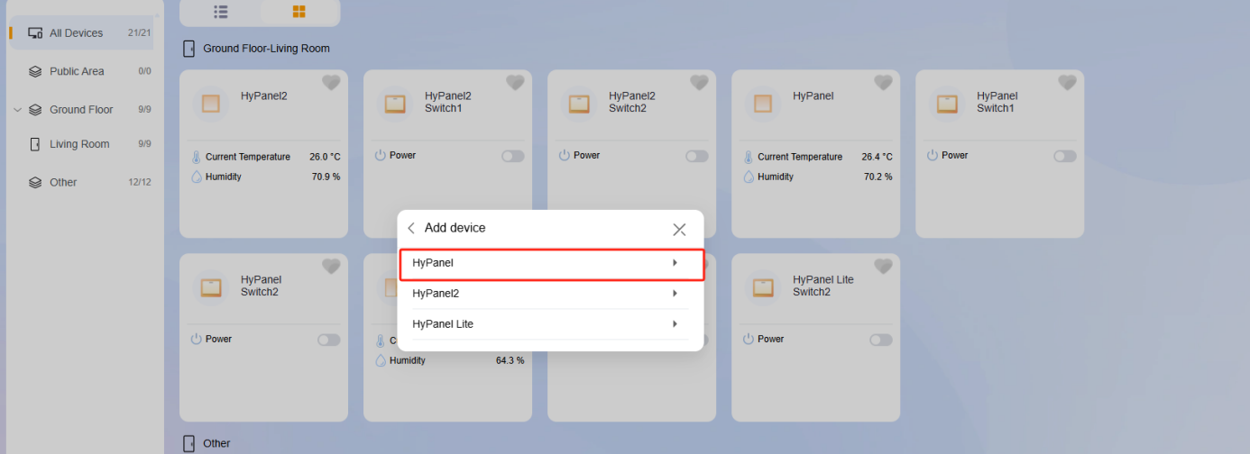
④ Put the ZigBee device into pairing mode. Wait for the HyPanel to detect it, then select the device.
⑤ Click Next.
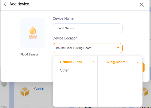
⑥ Set the device name and location, then click Done.
5. Create KNX scenes
Open ETS6 and follow the instructions below to create a KNX project and scenes.
TIP:
For more details on KNX programming, see this video.
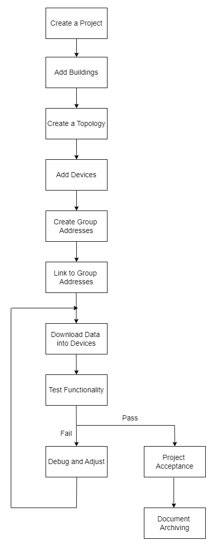
5.1. Create a Project
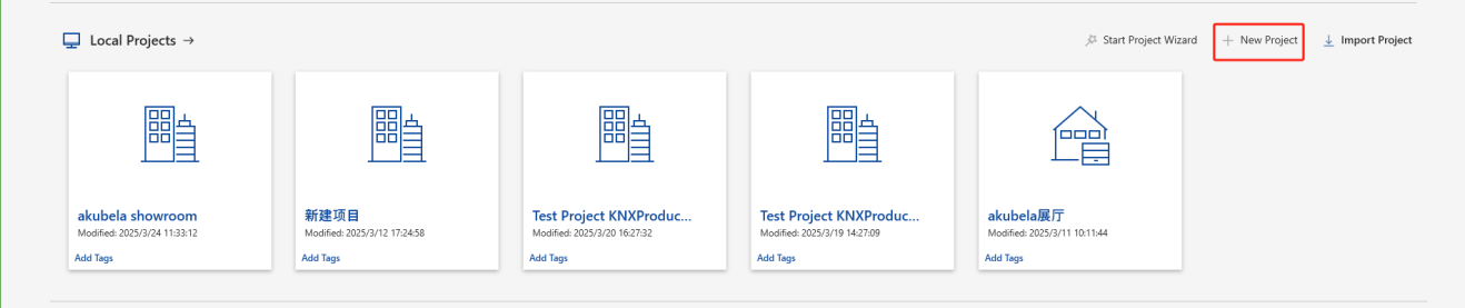
(1) Click New Project.
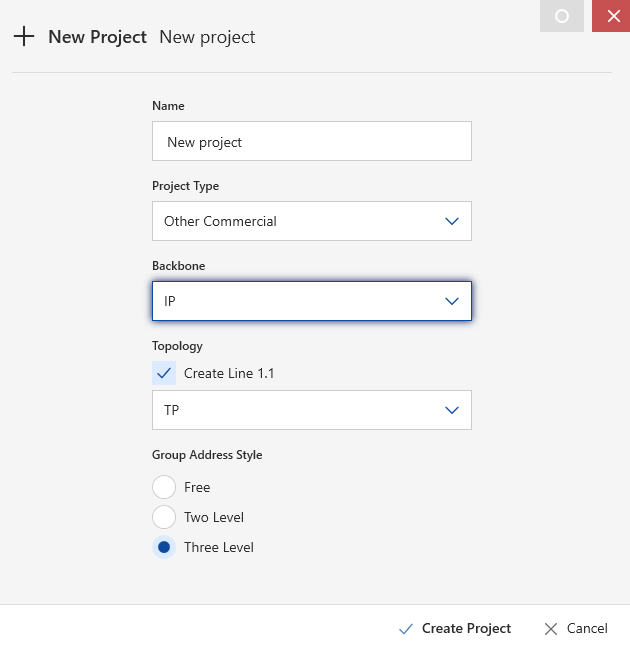
(2) Set the project details, then click Create Project.
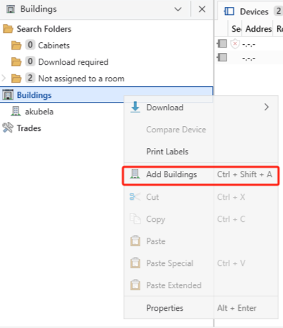
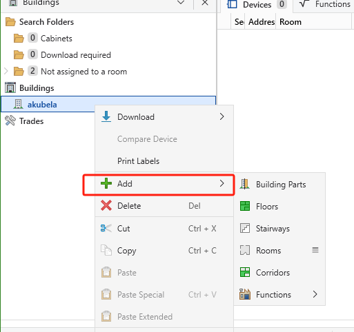
5.2. Add Buildings
5.3. Create a Topology
5.4. Import Database
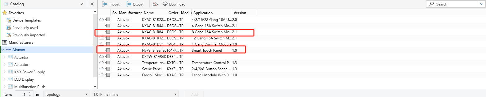
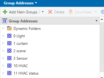
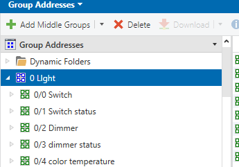
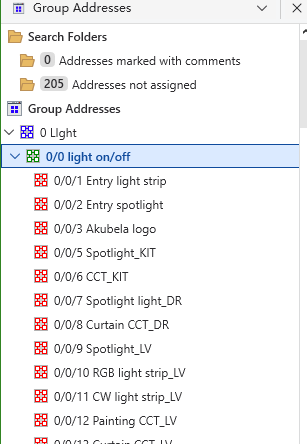
5.5. Create Group Addresses
You can customize the group address structure based on the needs of your KNX project. In this guide, we use a 3-level structure as follows:
(1) Main group: Organized by device type.
(2) Middle group: Based on the type of data.
(3) Sub group: Based on specific devices.
5.6. Configure Scene Parameters
We’ll configure scenes using an 8-gang 16A actuator and a Hypanel:
Channel A controls the ceiling lamp.
Channel B controls the spotlight.
Scenes Setup:
Leave Home scene: Turn off channels A and B.
Welcome Home scene: Turn on channels A and B.
(1) Configure scene parameters for 8 gang16A actuator
① Activate the Function for channel A.
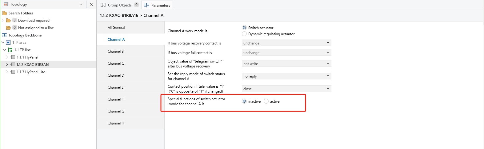
② Enable the Function of Scene option.
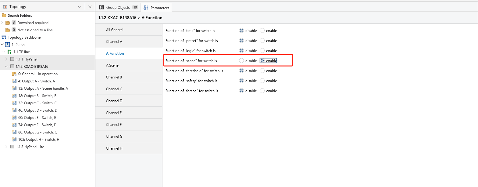
③ In the Scene settings, set Scene NO.1 to OFF, Scene NO.2 to ON.
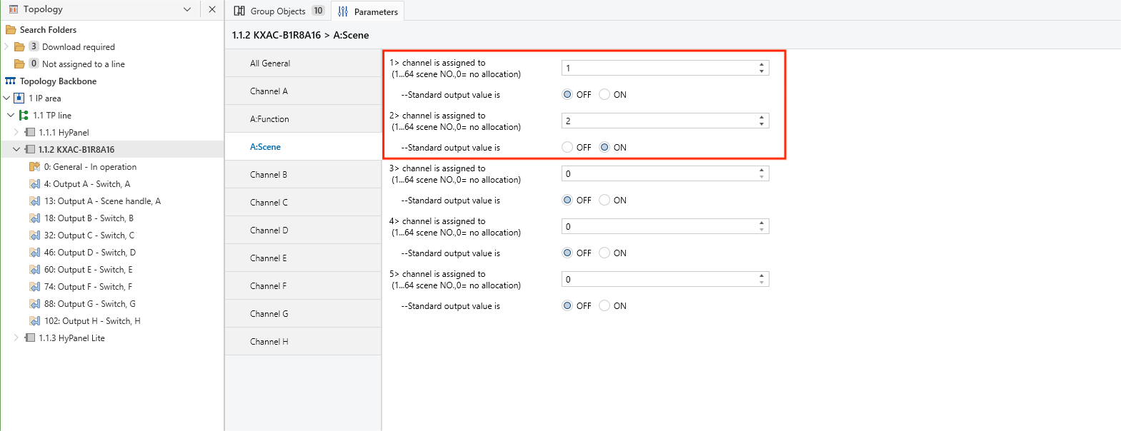
④ Repeat the same configuration for channel B.
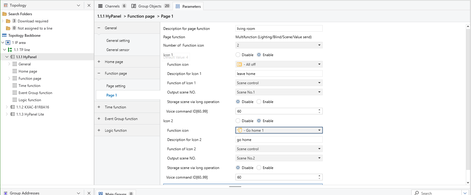
(2) Configure scene cards on HyPanel
① Enable the desired Page on the Function page.
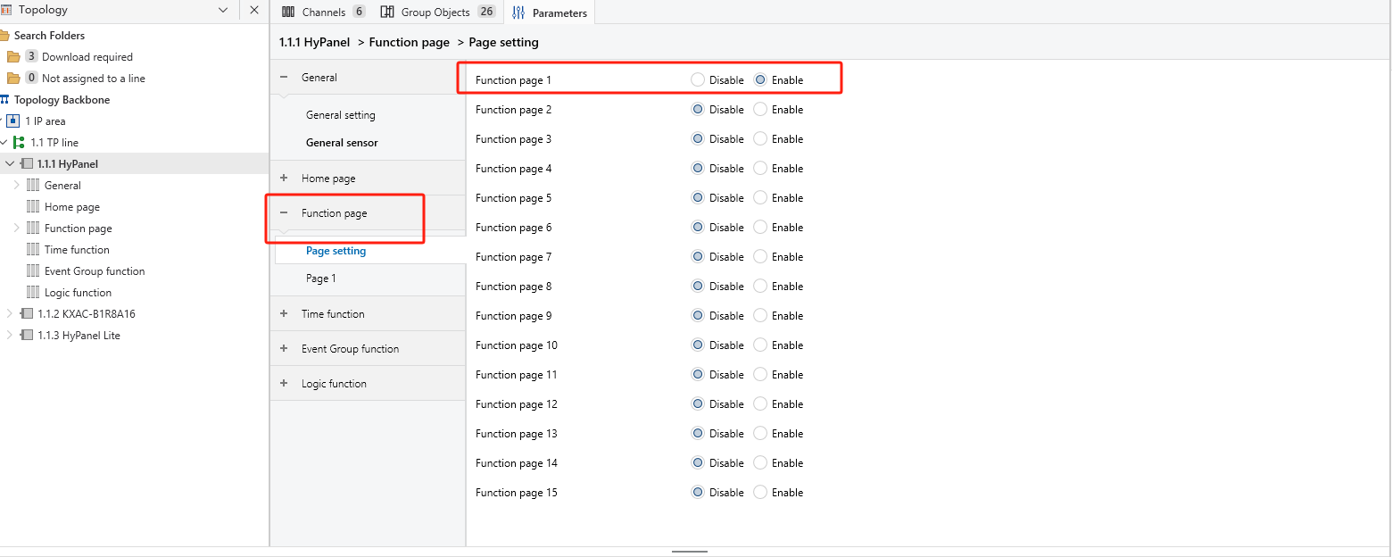
② On the selected Page X, set the button quantity, icon properties, and scene numbers. In this example, icon 1 is set to Leave Home and icon 2 to Go Home.
TIP:
For more detailed KNX device parameter settings, please refer to this guide.
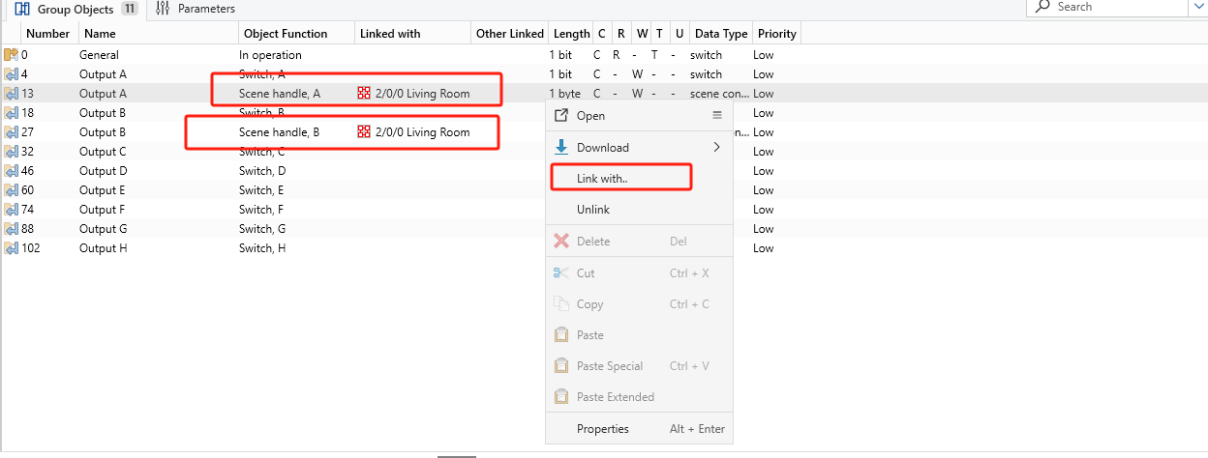
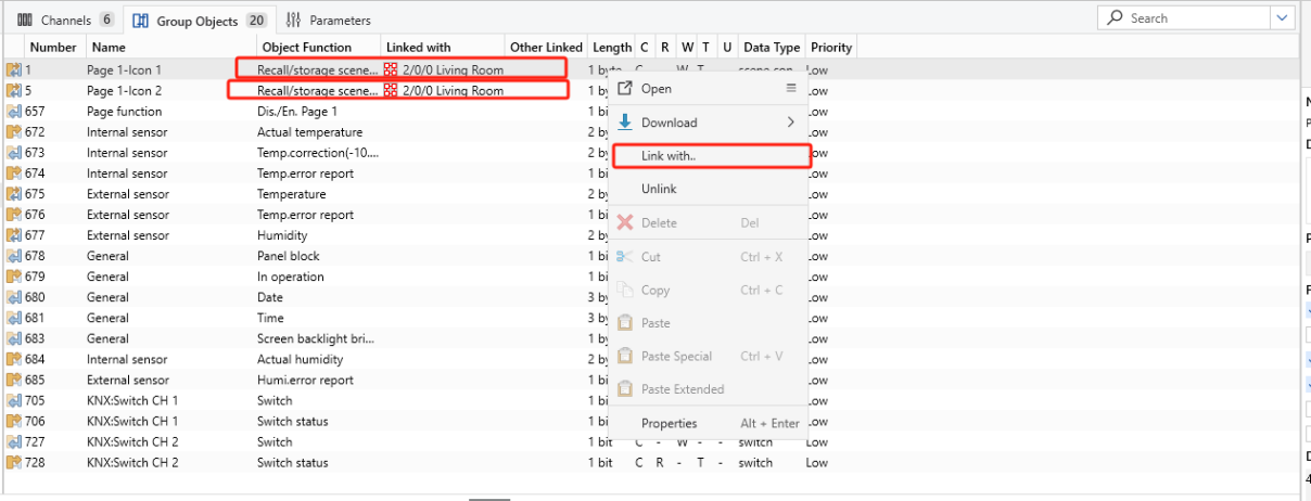
5.7. Link to Group Addresses
Configure Leave Home and Welcome Home scenes for the living room:
(1) Link channels A and B of the 8-Gang 16A actuator to the group address “2/0/0 living room”.
(2) Link HyPanel’s Page X -Icon 1 and - Icon 2 to the group address “2/0/0 living room”.
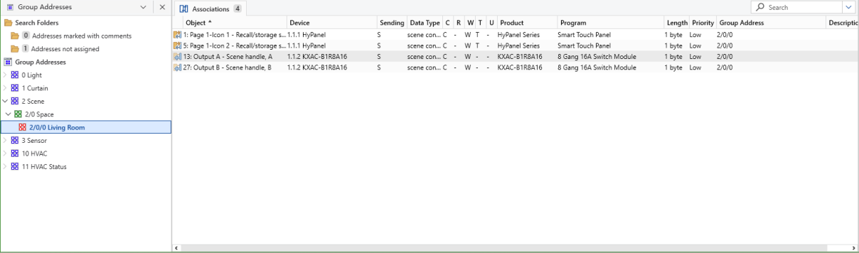
The assigned group addresses:
5.8. Download Data into Devices
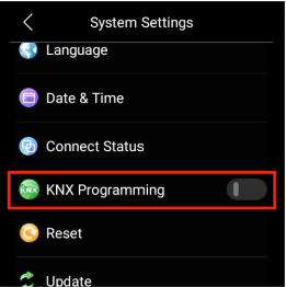
(1) Put devices in programming mode.
Device | Programming Method |
HyPanel |
1. Swipe down from the top of the screen. 2. Go to |
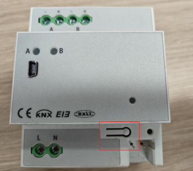
8-Gang 16A Actuator |
Press the programming button. The indicator will light up, indicating that the device has entered programming mode. |
(2) Connect the USB Interface to both your PC and KNX devices.
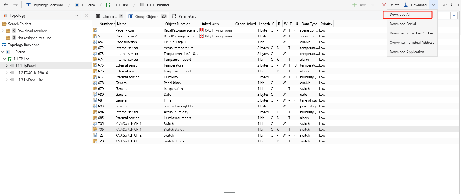
(3) Click on the HyPanel, and select Download > Download All to download project data into the device.
(4) Repeat the previous step to download data into the actuator.
TIP:
Select the appropriate download option based on your project requirements.
Option | Description | Programming Mode |
Download All | Download all project data in ETS to the corresponding device. | YES |
Download Partial | Download only the parts have not been downloaded before. | NO |
Download Individual Address | Assign Individual address to KNX device. | YES |
Overwrite Individual Address | Assign individual address to KNX device by overwriting known address. | NO |
Download Application | Download the application into the device. | NO |
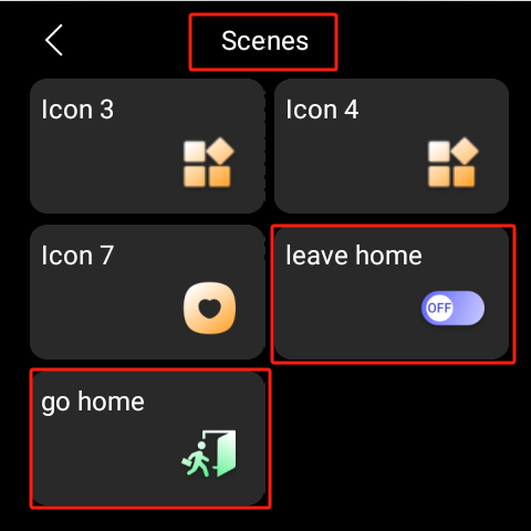
After downloading, the scene card will display on the Scenes screen.
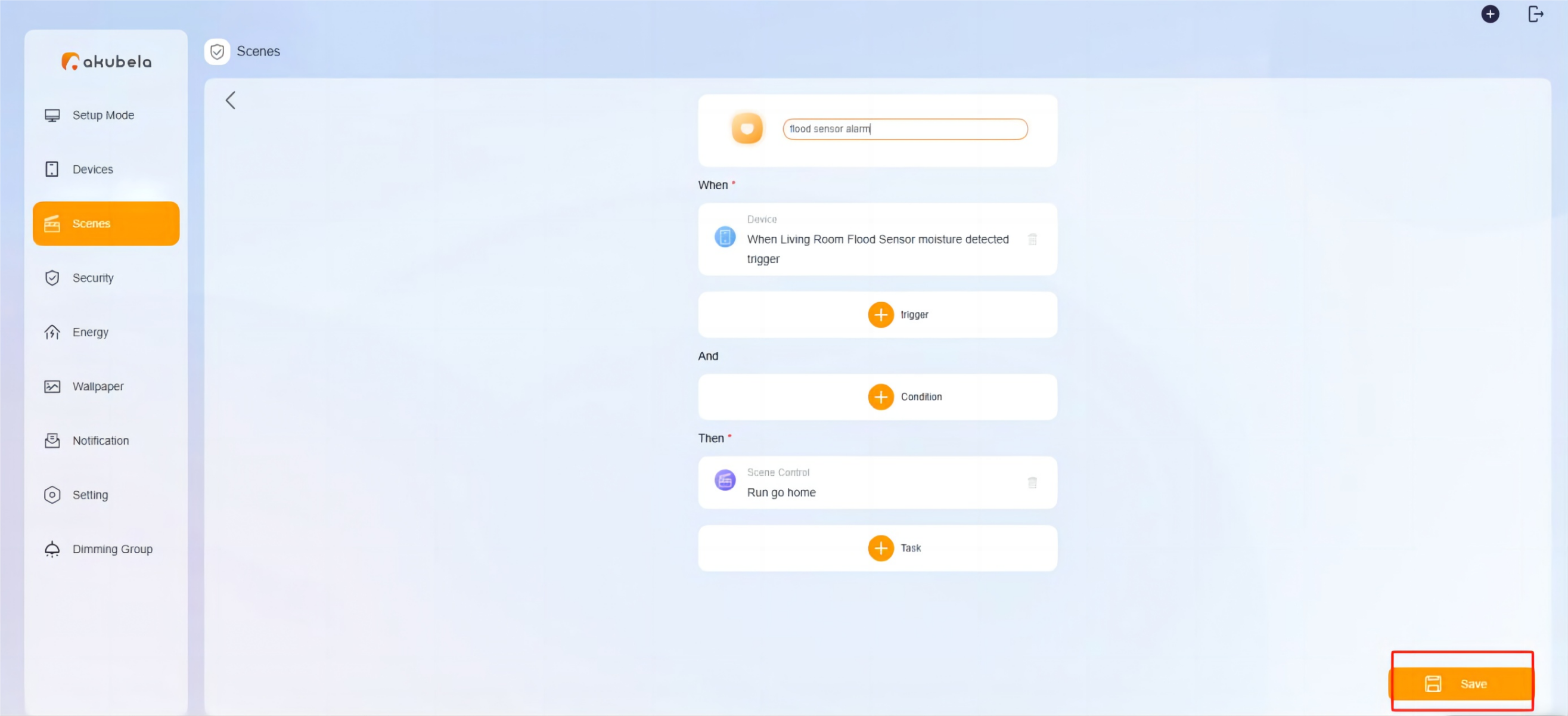
6. Create KNX+Zigbee Scenes
Example:
Scene Name: Flood sensor alarm.
Condition: The Flood Sensor is triggered
Task: Activate the Welcome Home scene.
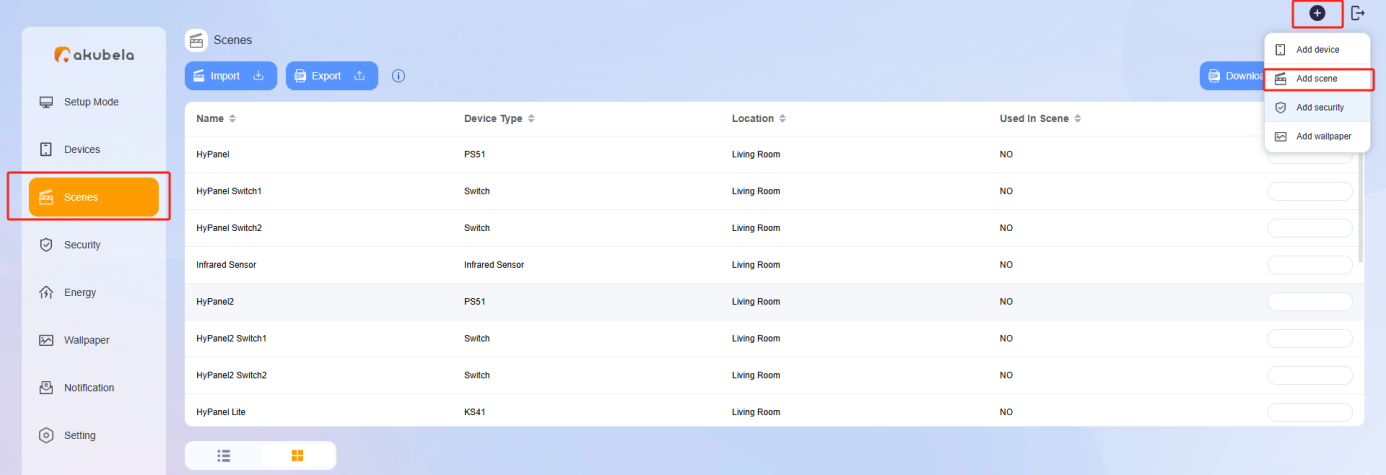
Path: On the user web portal, click Scenes >
 > Add Scene.
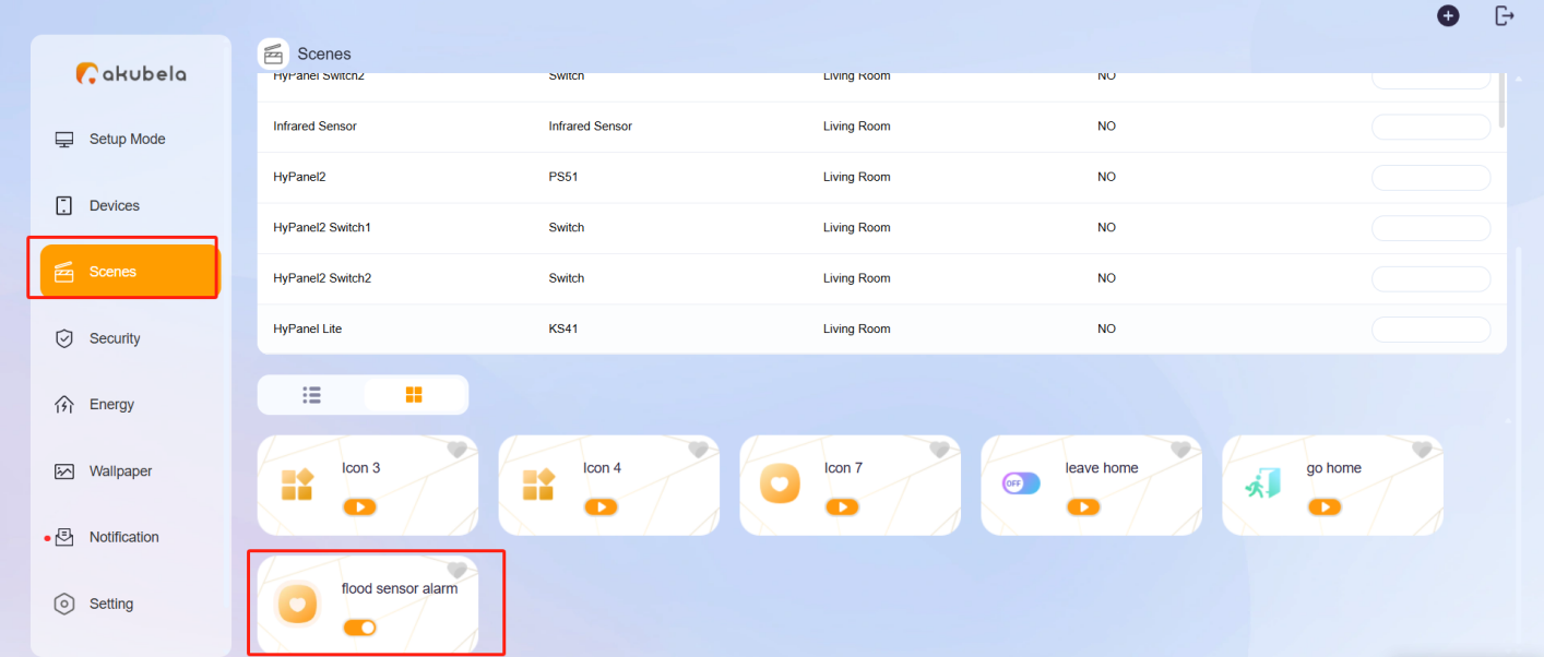
Once completed, the scene will appear in the user web portal’s Scene interface, and the BelaHome app’s Automation screen.
7. HyPanel UI Configuration
The settings include hiding unnecessary devices or spaces, as well as displaying family photos.
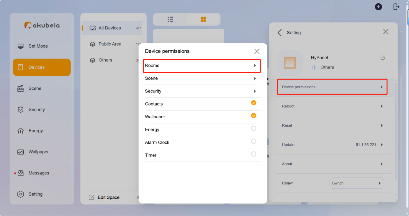
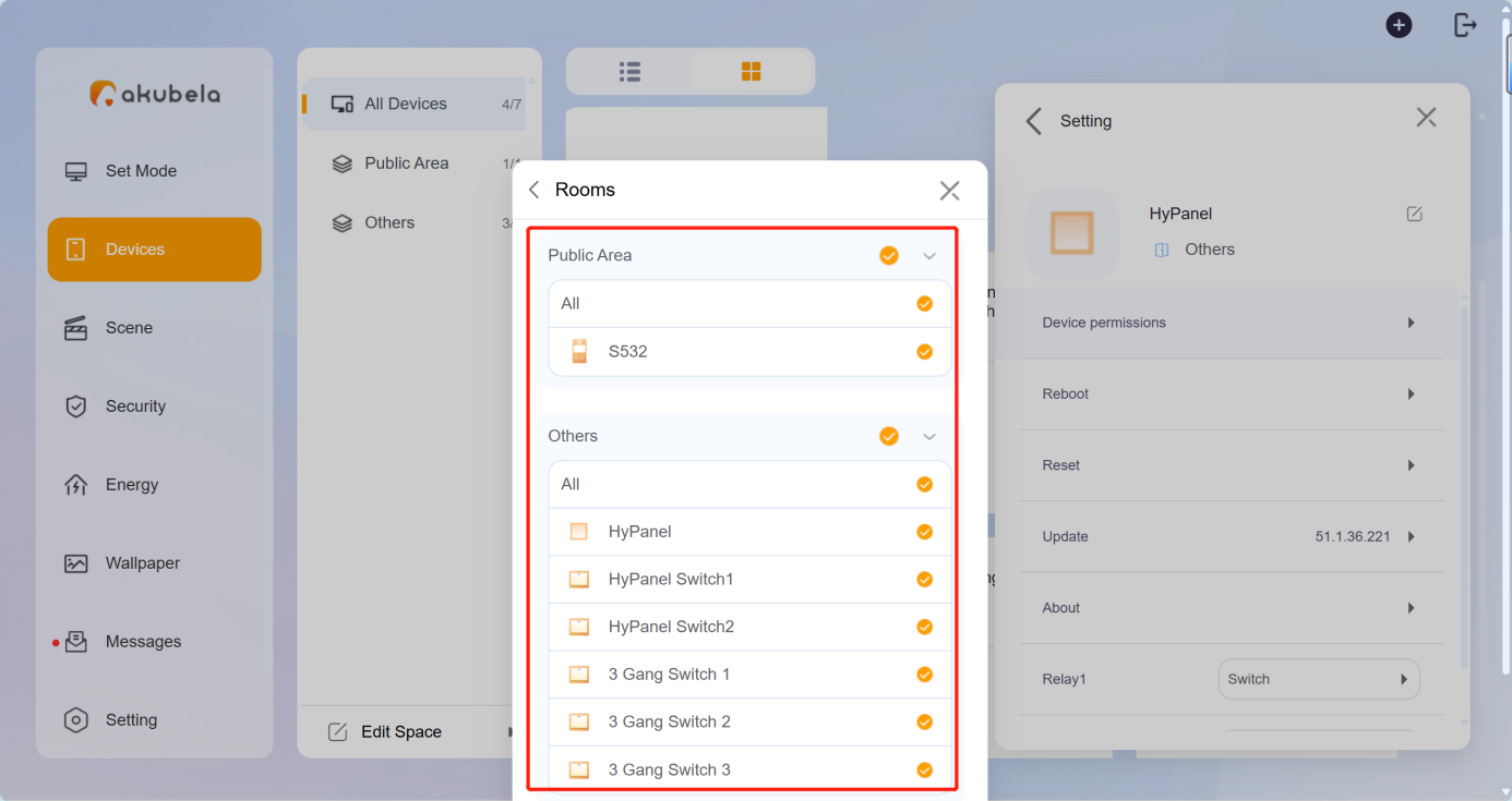
7.1. Hide Devices or Spaces
To display or hide rooms or devices in a room:.
Configuration Path: On user web portal, select the desired HyPanel device, and click  > Device permissions > Rooms.
7.2. Display family photos
Click ![]() > Add Wallpaper, and add the photos to the desired panel.
> Add Wallpaper, and add the photos to the desired panel.
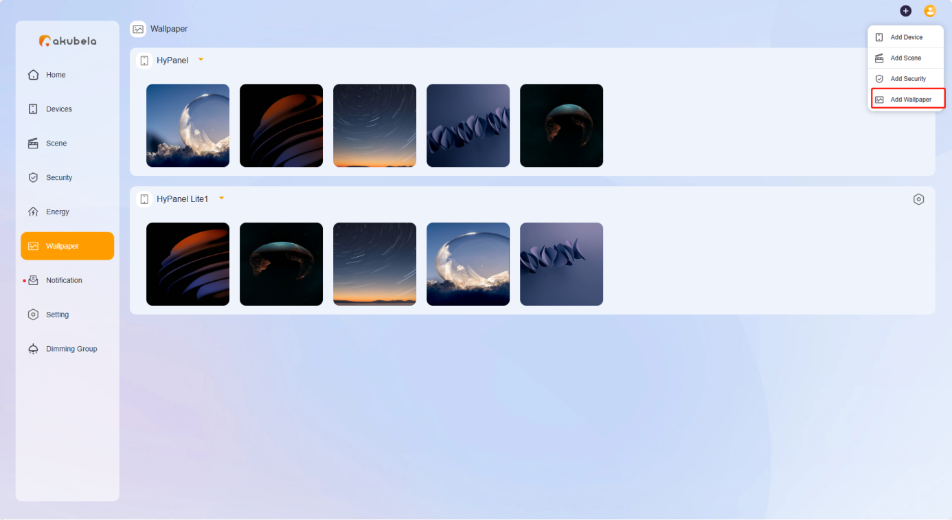
The added photos will appear in the Wallpaper interface of the user web portal, and be sent to the selected panel.
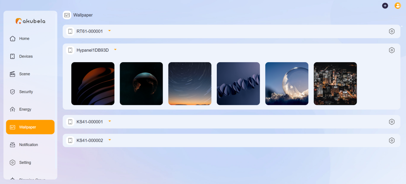

NOTE:
To send the added photo to other devices of the same model, click
> Send to Device on the Wallpaper interface of the user web portal.
To display photos on the selected panel, go to the panel’s
> Display > Screen Saver Style screen, and select the Photo Wall style.
8. Download App and Use
8.1. Download BelaHome App
Android: Search BelaHome in the Google Play Store.
iOS: Search BelaHome in the App Store.
8.2. Log into the App
The login credentials will be sent to the administrator's email address registered on akubela Cloud. Users can log in using the following methods:
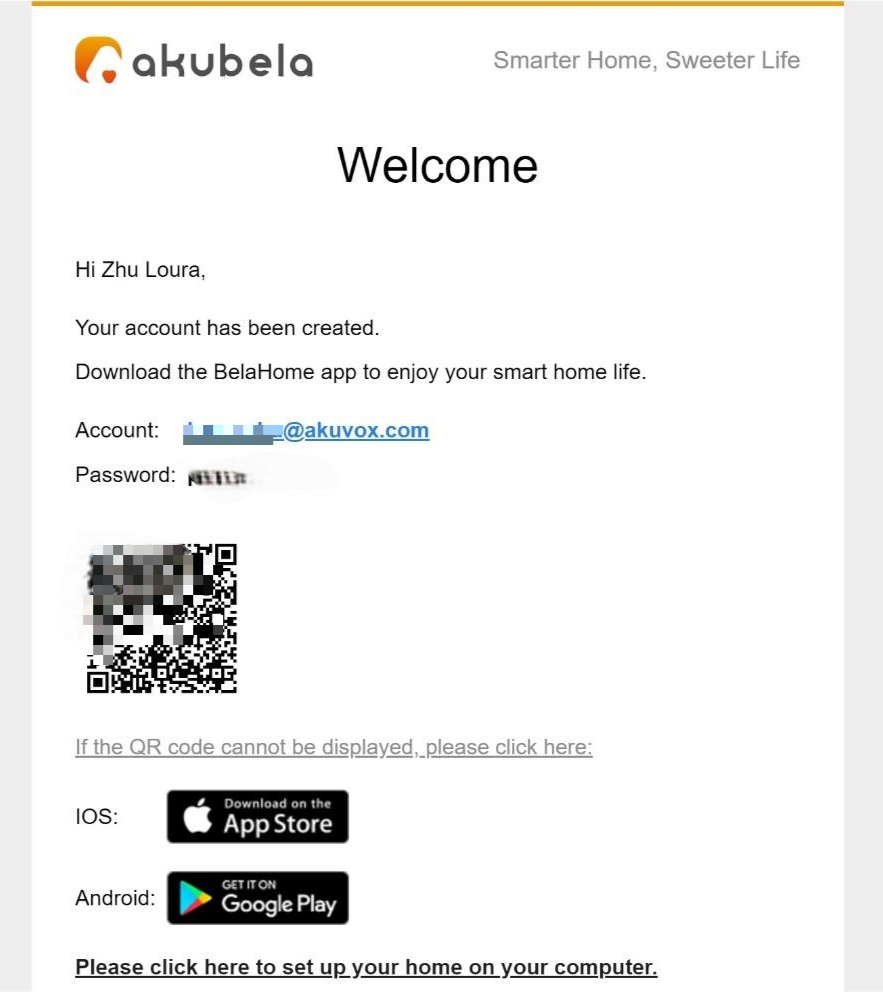
Scan the QR.
Log in with the account credentials.
8.3. Use the App
Here are some frequently used functions in the App.
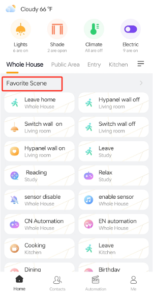
Save frequently used scenes for quick access.
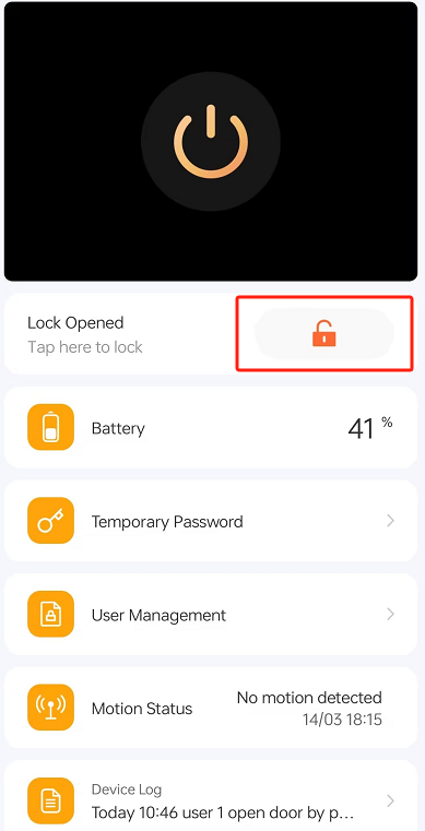
Unlock the door.
For door phones
① Tap the corresponding device on the Home screen.
② Tap the unlock button.
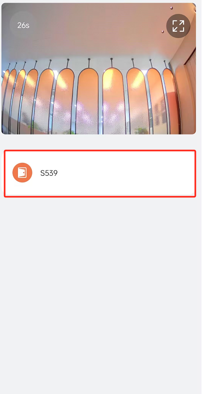
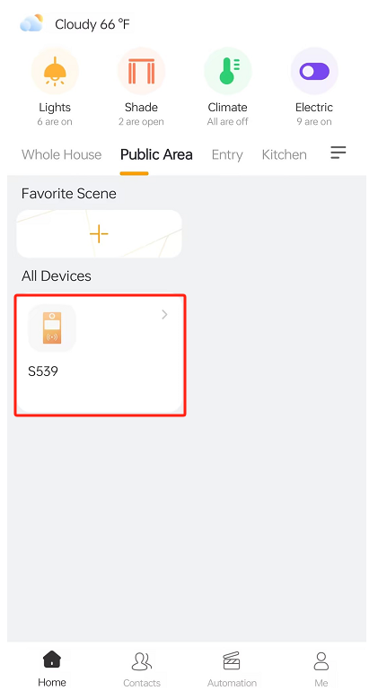
For SL50
Select the SL50 device and tap the unlock button.
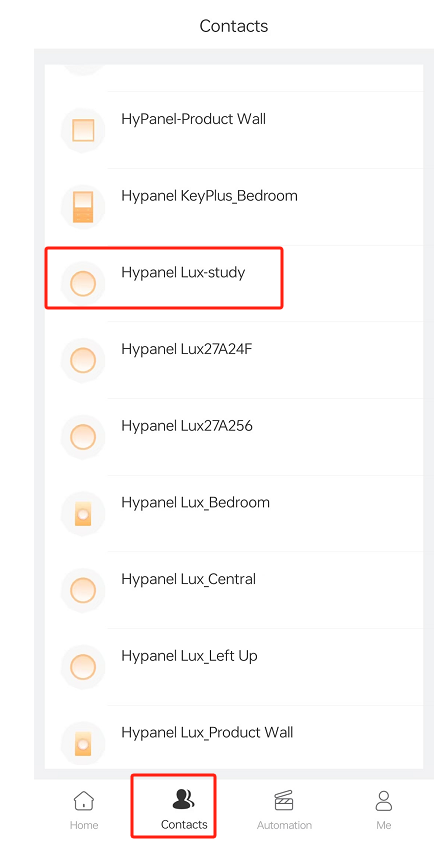
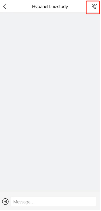
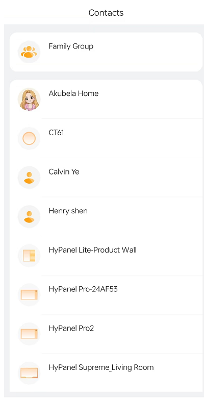
Make calls
Tap Contacts, enter the desired device, and tap  .
.
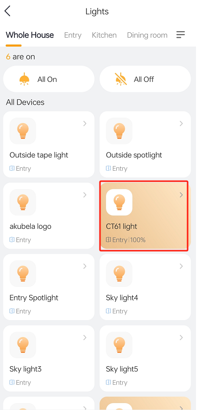
Turn on/off devices
Tap the desired device on the Home screen.
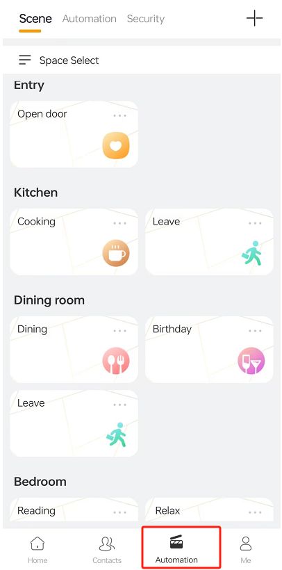
Activate scenes
Tap Automation, and tap the scene card to trigger the task, which can be added to the home screen for quick access.
Check Notifications
Go to Contacts, select a contact, and the messages and call logs display.
TIP:
For more functions, refer to the BelaHome App User Guide.