This guide is intended for: ①Installers setting up device wiring in hotels or rental properties, and ②Hotel managers creating and configuring hotel rooms.
In this solution, HyPanel Lite (KS41), HyPanel Elite 7 (PG42), and G31 Gateway can function only as sub-gateways.
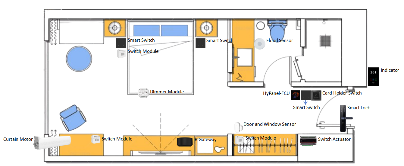
Example of Hotel Room Layout and Device Placement Locations
Before Getting Started
Obtain Cloud Accounts
Installer account: Obtain this account from your distributor and contact akubela technical support to enable the GRMS permission.
GRMS platform account: Obtain this account from your installer.
Collect Device information (Model, MAC, etc.)
Reception | |||||||
System device | Intercom | Others | |||||
Front Desk | |||||||
Staff Area | |||||||
Room | |||||||
System device | Panel | Lighting | Climate | Security | Intercom | Others | |
Entrance | Smart Lock | Electronic Doorplate | |||||
Hallway | HyPanel Lite(Fan Coil version) HyPanel Pro (PoE version) HyPanel (PoE version) | Switch Module | Door/ Window Sensor | Key Card Switch | |||
Cabinet | Switch Actuator | ||||||
Bathroom | Smart Switch | Flood Sensor | |||||
Living Room/Bedroom | Dimmer Module Switch Module Smart Switch | Curtain Motor | IR Controller | ||||
Upgrade Devices
Collect device firmware versions
You can use the following table format to record firmware versions:
Device | Required Version |
HyPanel Pro | 71.1.38.426 or later |
HyPanel Lite | 41.1.39.126 or later |
HyPanel | 51.1.39.426 or later |
a. Download the latest firmware from the Knowledge Base.
b. Update the device on the cloud by following the guide.
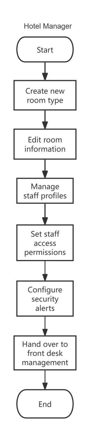
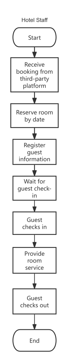
Task Overview for Hotel Manager and Staff
Tasks for Hotel Manager | Tasks for Hotel Staff |
|
|
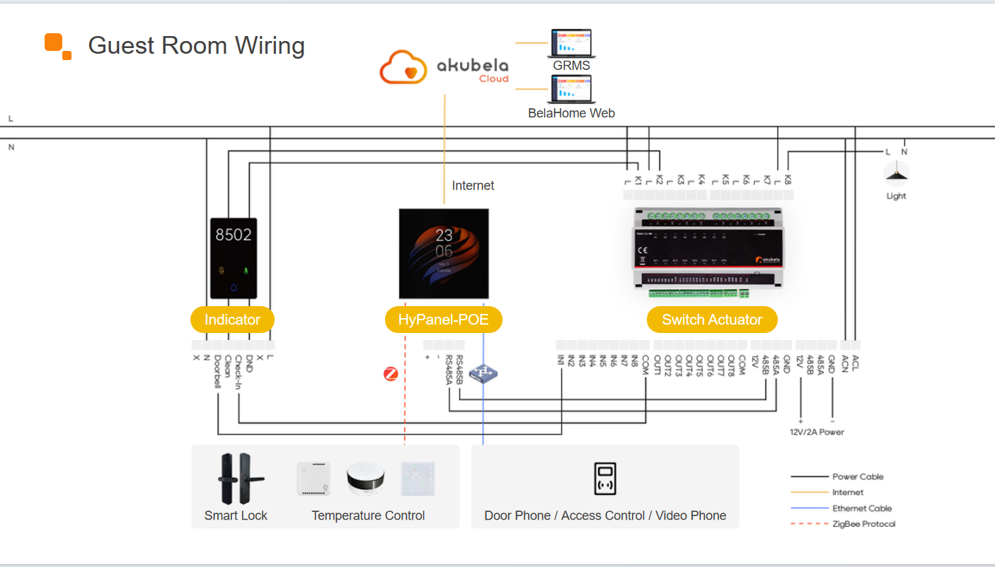
Wiring, Power Supply, and Internet Connections
Wiring
Switch Actuator R8
NOTE:
The recommended maximum cable length is 10 meters.
HyPanel is used as an example in this demonstration.
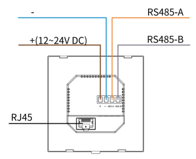
IP-485 Multifunctional Gateway R10
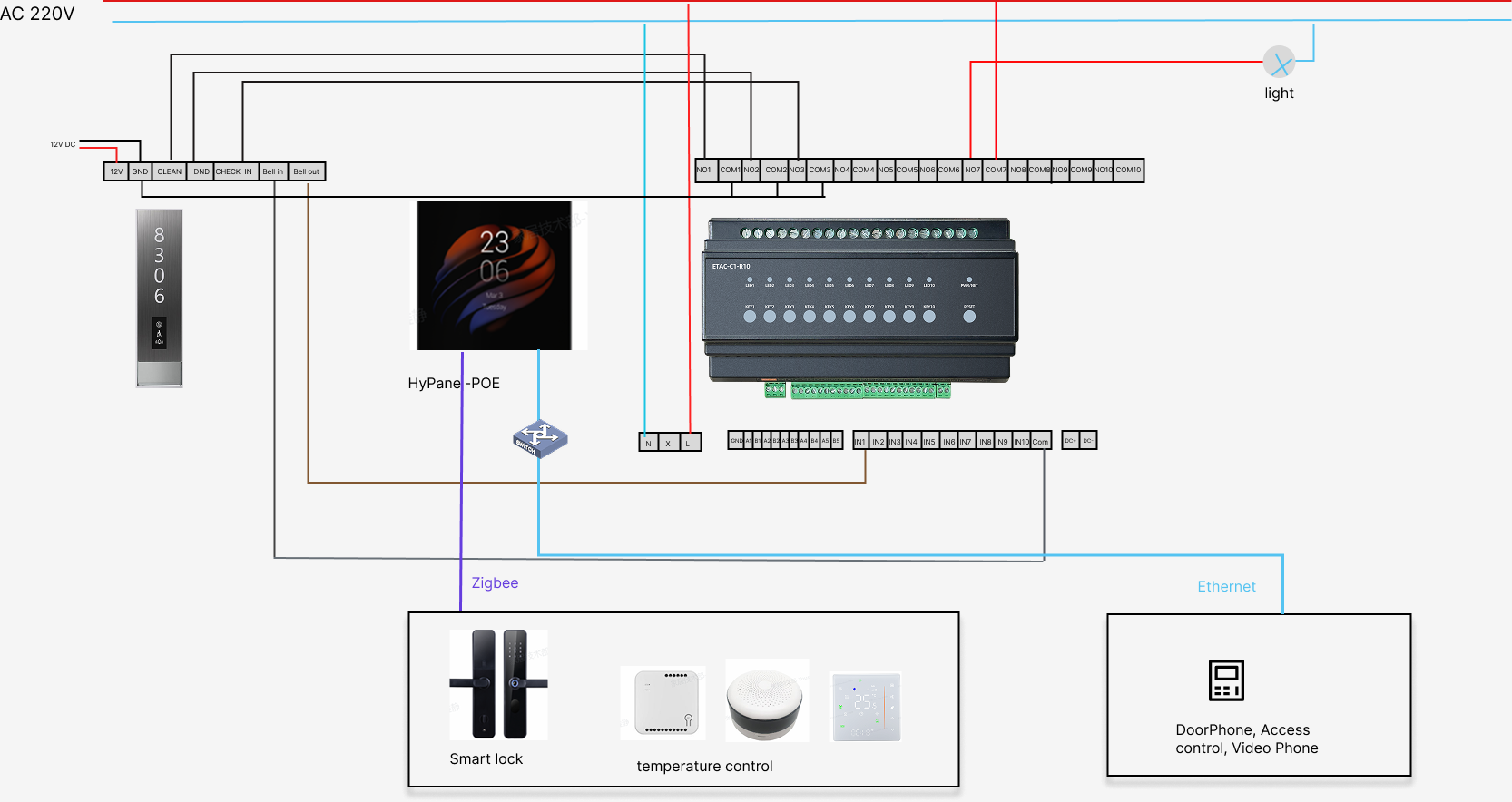
NOTE:
When connecting both high-voltage and low-voltage relays, leave one relay channel unused between them.
Example: when a low-voltage device is connected to NO1/COM1, the high-voltage device should start from NO3/COM3.
If high-voltage relays need to be used, power the Switch Actuator with a 100–240 VAC supply through the L and N terminals. This ensures optimal performance and helps extend the actuator’s service life.
HyPanel is used as an example in this demonstration.
Connect Devices to Power
Refer to the instructions below to power on devices. For other devices, please refer to their user manuals for detailed guidance.
Device | Operation |
HyPanel Pro (PG71-PoE-EU) | Powered by PoE
|
HyPanel (PS51-PoE-EU) | Powered by PoE
|
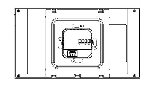
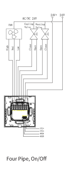
HyPanel Lite (Fan Coil Version) |
|
F2 Lock | Powered by 4 AAA alkaline batteries |
RS485 Switch Actuator | 12V/2A power adapter connected to the 12V and GND terminals |
IP-485 Multifunctional Gateway | PoE, 12-24VDC, or 100-240VAC |
Smart Switch | 100-240V AC power supply |
Door/Window Sensor | Powered by CR2032 battery |
Curtain Motor | 100-240V AC power supply |
IR Controller | 5V/1A adapter+USB cable |
Flood Sensor | Powered by CR2032 battery |
Connect Devices to the Internet
Refer to the instructions below to connect devices to the internet.
Device | Operation |
HyPanel Pro (PG71-PoE-EU) | Use an Ethernet cable or connect to Wi-Fi |
HyPanel (PS51-PoE-EU) | Use an Ethernet cable or connect to Wi-Fi |
HyPanel Lite (Fan Coil Version) | Use an Ethernet cable or connect to Wi-Fi |
IR Controller | Press the button until green LED flashes slowly |
Zigbee Devices Pairing
Device | Operations |
Door/Window Sensor | Hold reset button for 5s until LED blinks |
Flood Sensor | Hold reset button for 5-10s until LED blinks |
Refer to the instructions below to put the Zigbee devices into pairing mode. You can refer to this guide for more devices’ instructions.
Project Creation
Create a Project on the Cloud
Create a community project, then add buildings, homes, administrator email addresses, home center devices, and their MAC addresses.
TIP:
For detailed instructions on creating a community project, please refer to this guide.
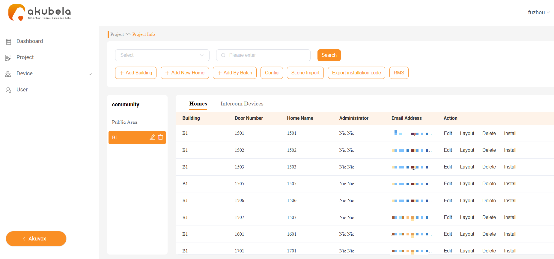
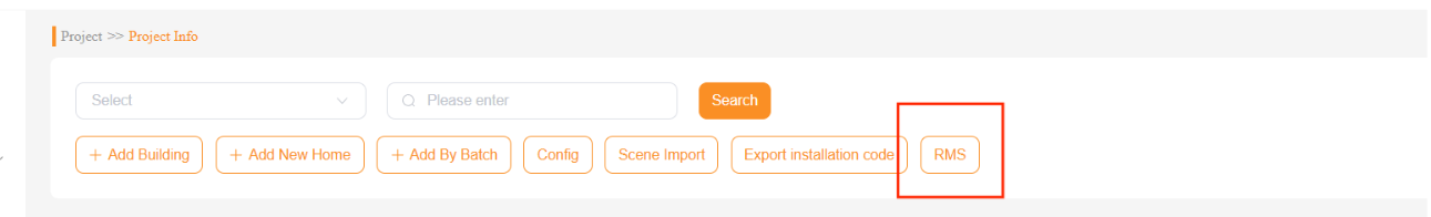
On the project’s Details screen, click on RMS > Add to add the hotel manager(s) and staff accounts.
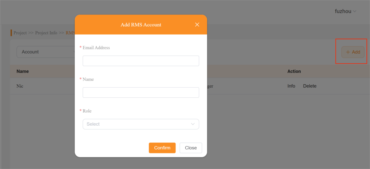
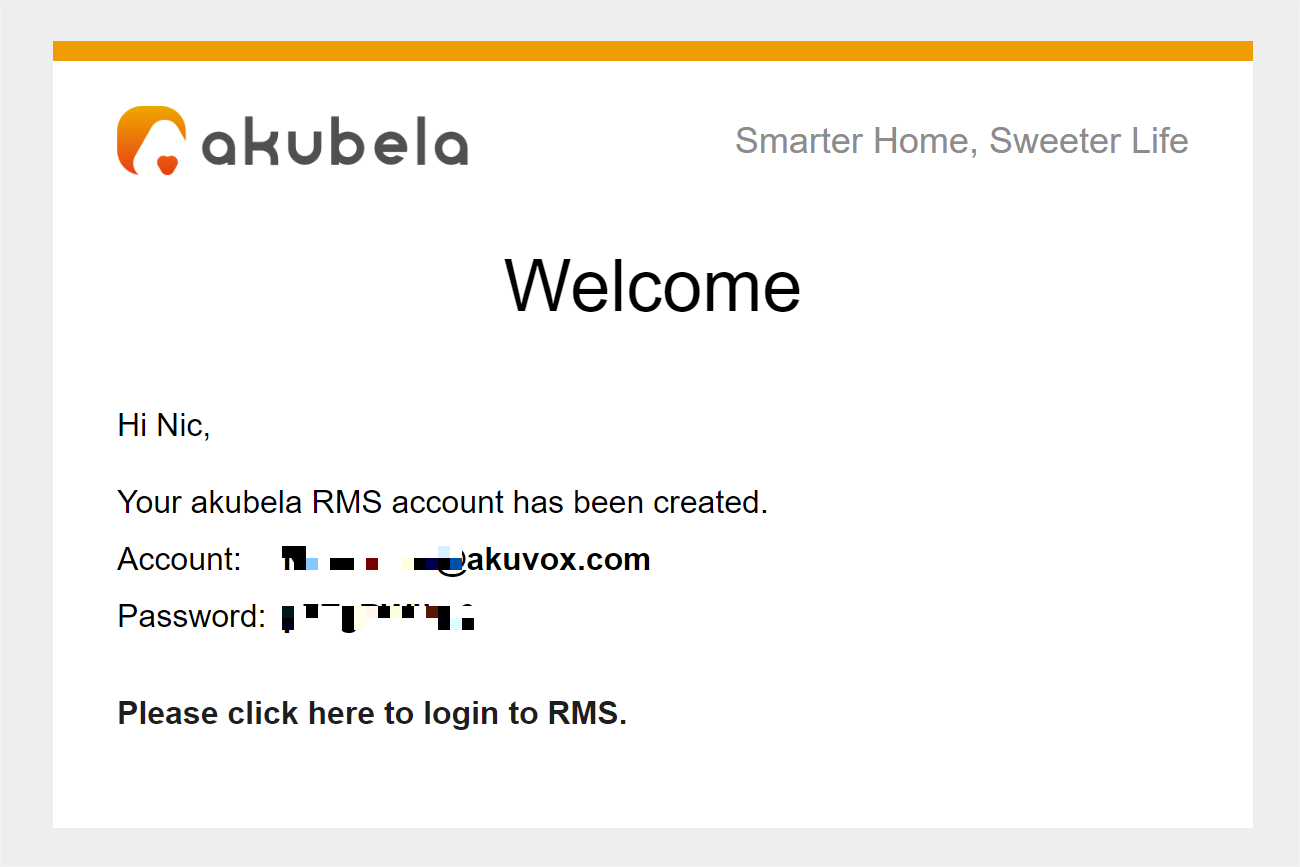
Once created, each manager and staff member will receive an email containing their login credentials and login link.
Configure Room Settings
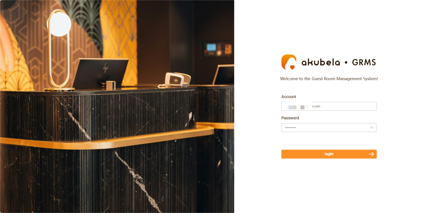
Use the manager account to log into the GRMS platform.
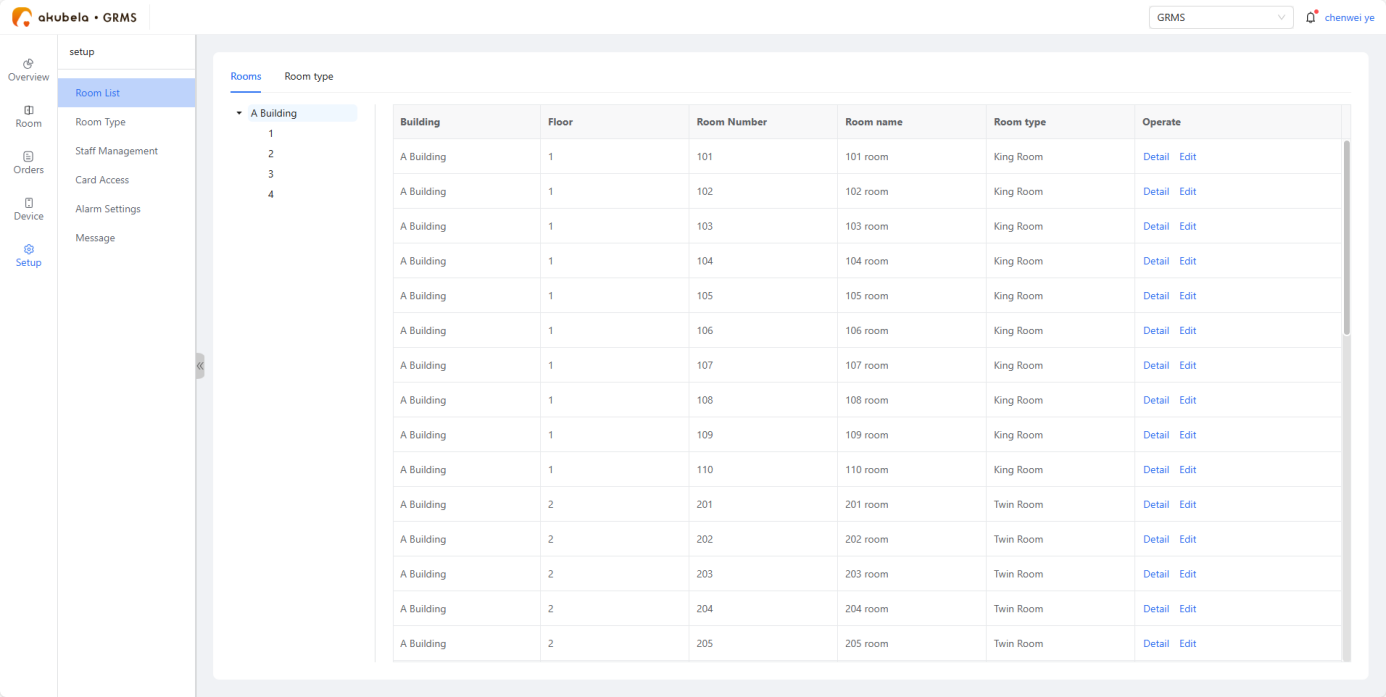
Configure settings such as room types, staff management, access permissions, alarm settings, and more.
NOTE:
Community projects created on akubela Cloud automatically sync with the GRMS platform, with all changes (e.g., room names/numbers) updating in real-time across both platforms.
Go to Room Type > New room type, then set the room type, bed numbers, and maximum occupancy.
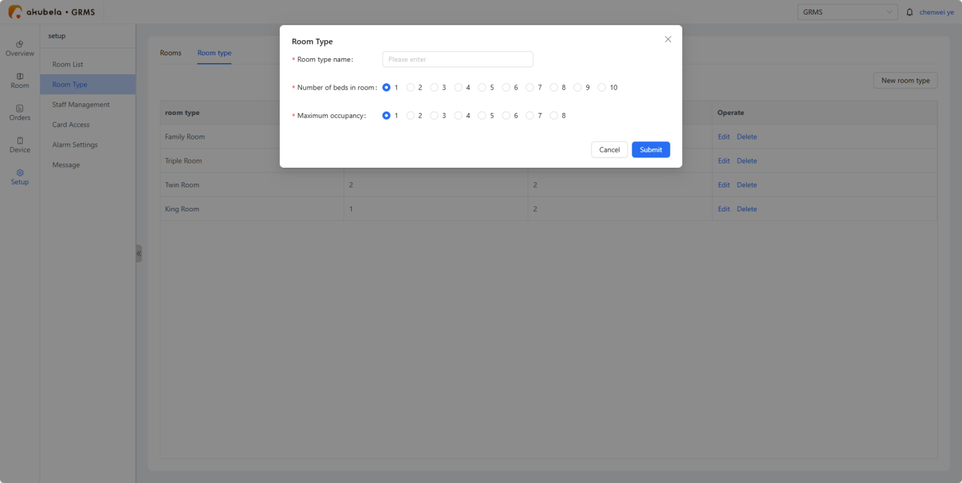
NOTE:
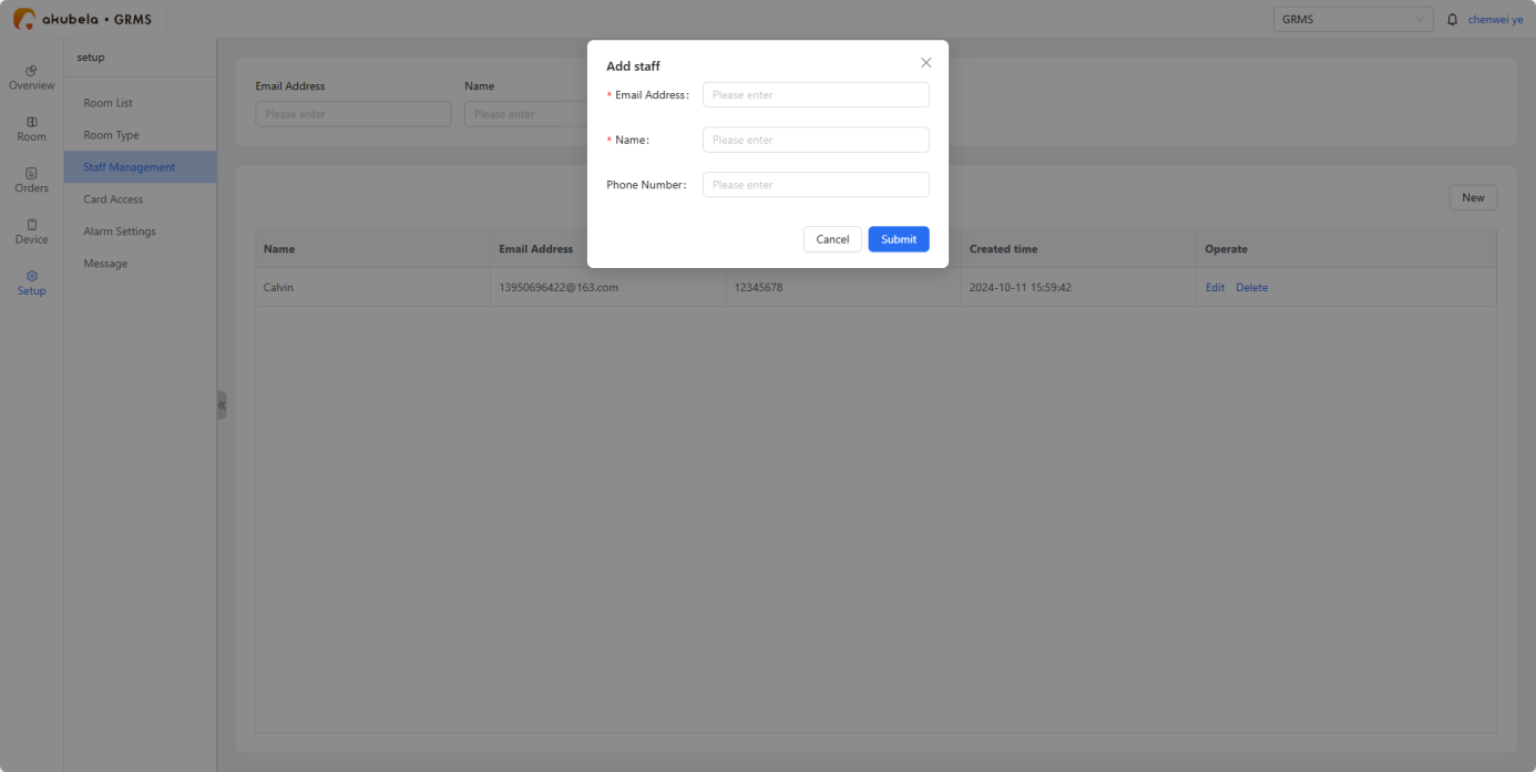
The Staff Management section is accessible only to manager accounts.
Go to Staff Management > New, then enter staff name, email address, and phone number.
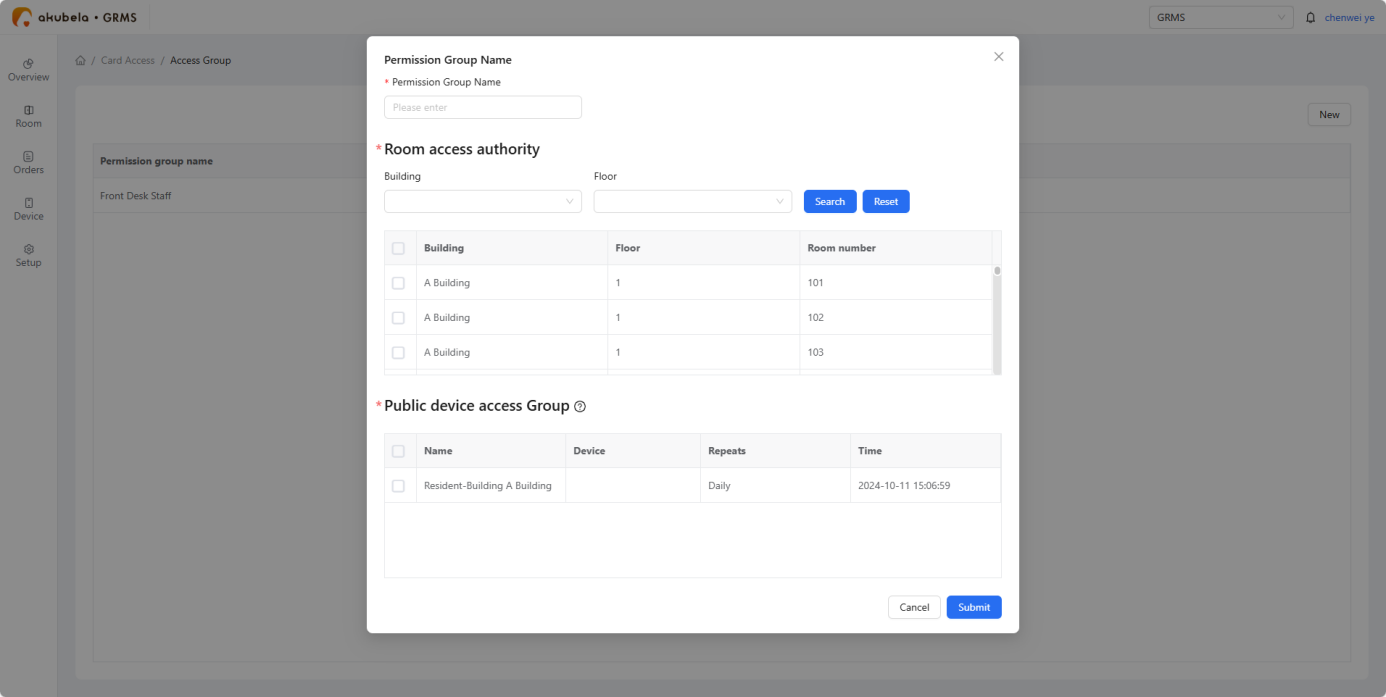
Create permission groups. Go to Card Access > Permission Group > New, name the group, and set the access rights for rooms and public areas.
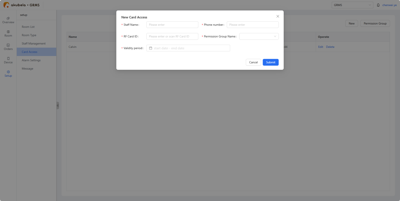
Add access cards. Go to Card Access > New. Enter the required information.
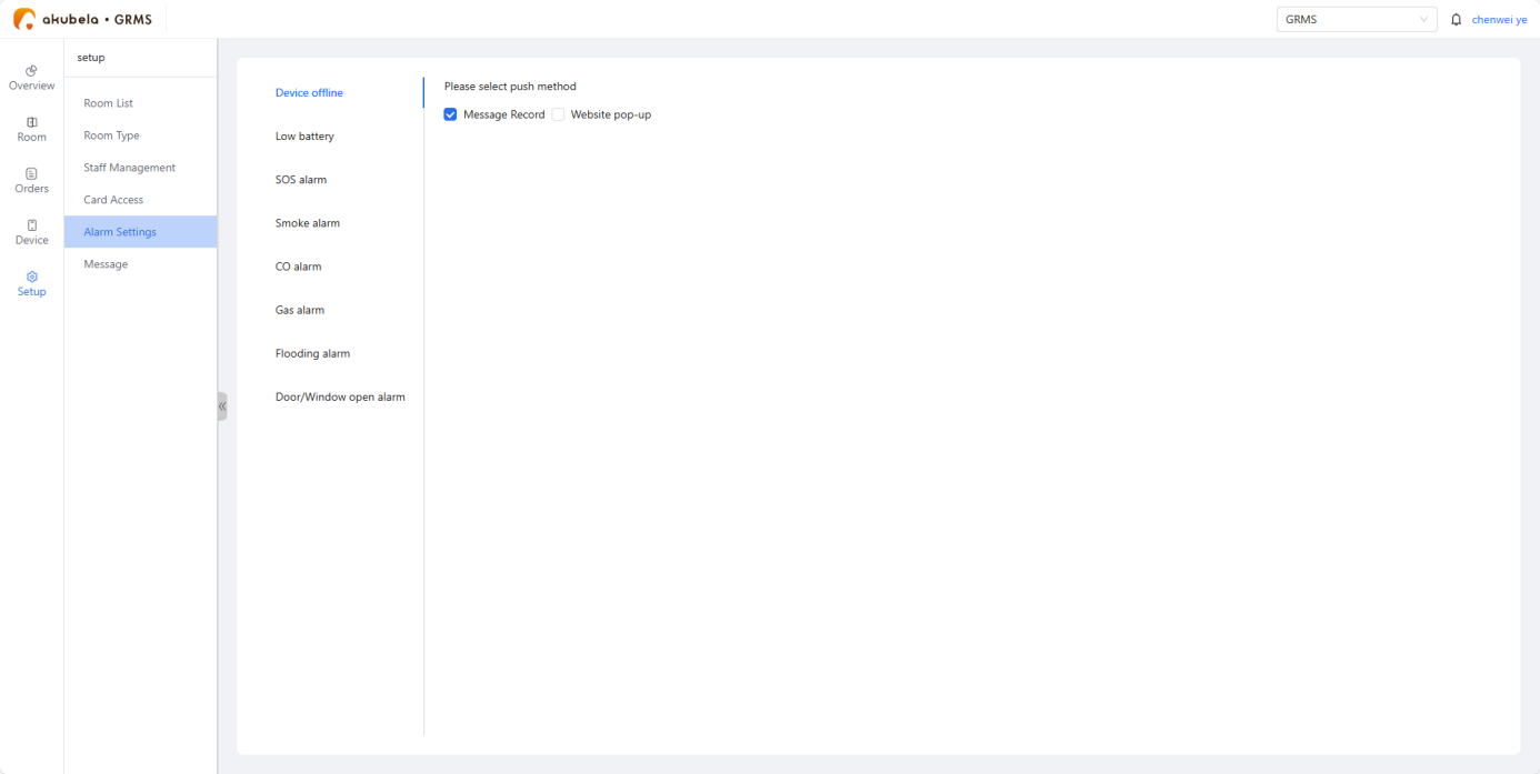
Configure alarm notification settings
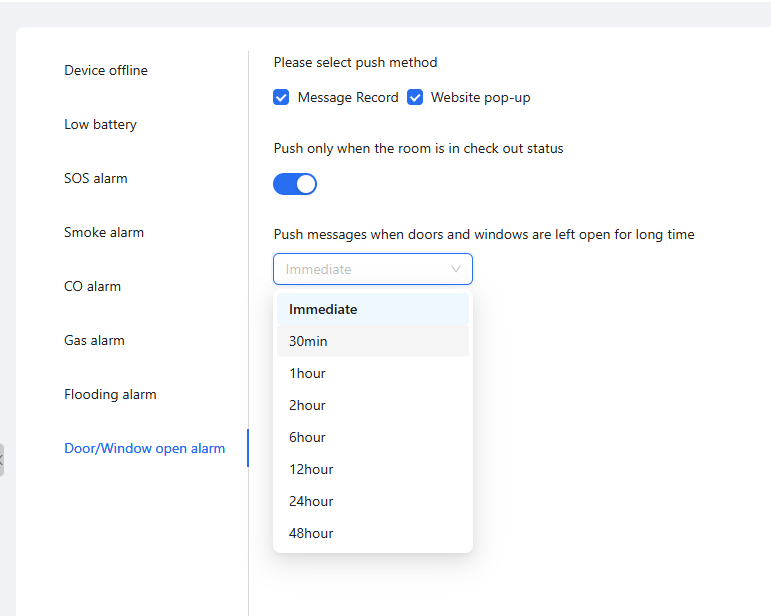
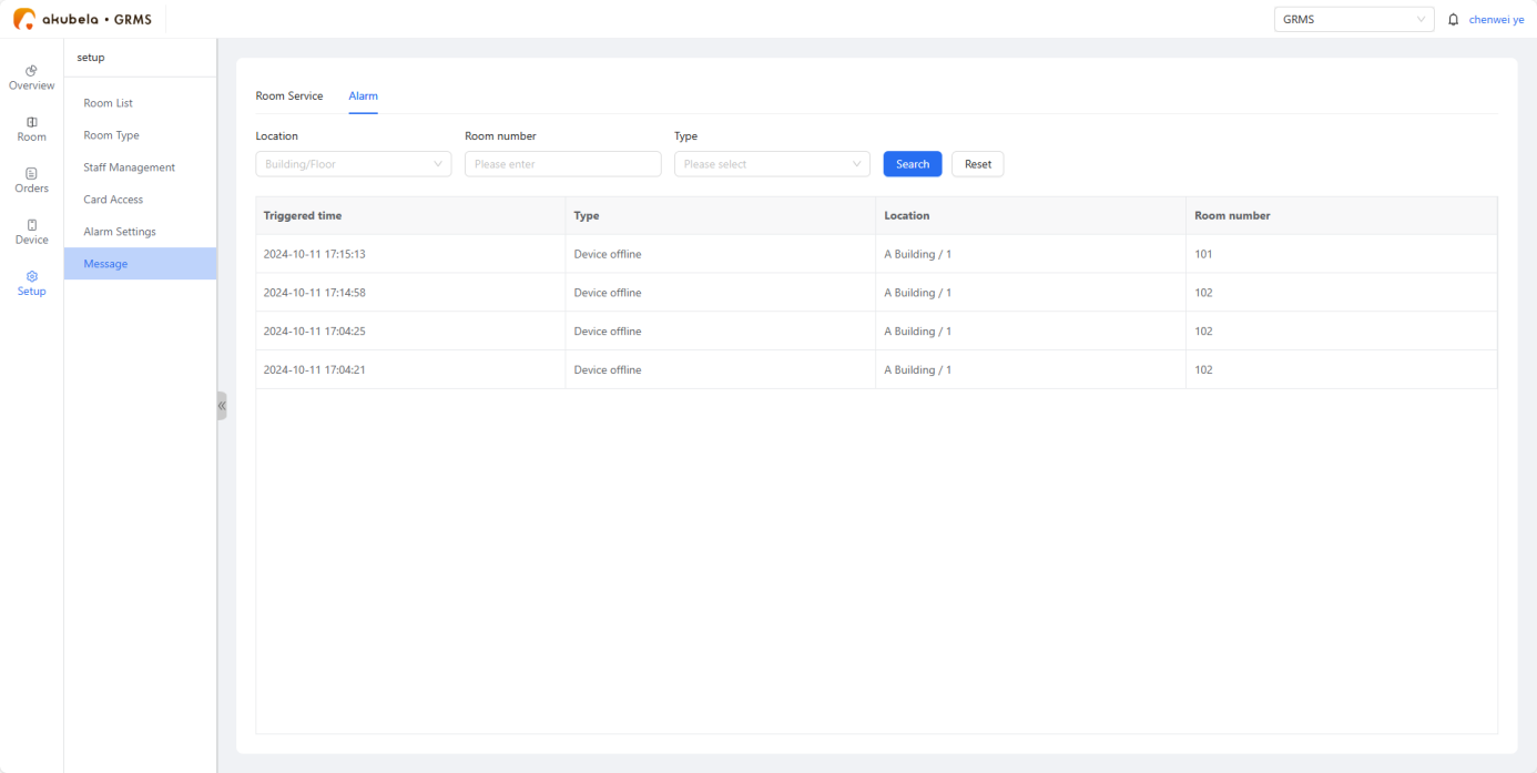
Go to Setup > Alarm Settings, select the alarm type, and choose one or more notification methods:
Send notifications to the GRMS system (displayed under Message > Alarm).
Show pop-up alerts directly on the platform.
TIP:
The door/window alarm allows flexible settings like delay time and activation during checkout only. It alerts staff immediately if a door is left open, reducing security risks.
Device Configuration
Add the RS485 Switch Actuator
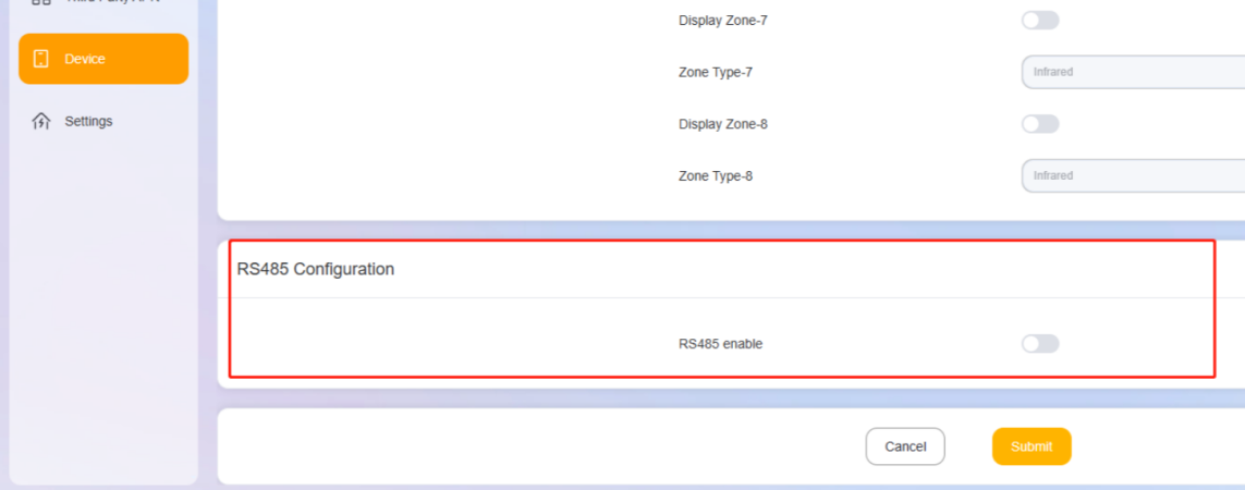
Log in to the device web portal of the HyPanel that is connected to the Switch Actuator, and go to Device > RS485 Configuration to enable RS485 function.
Set Connection Type to akubela.
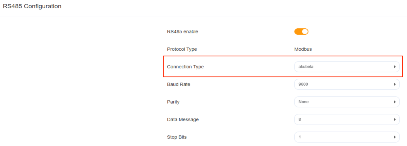
Name the device, and set the device address.
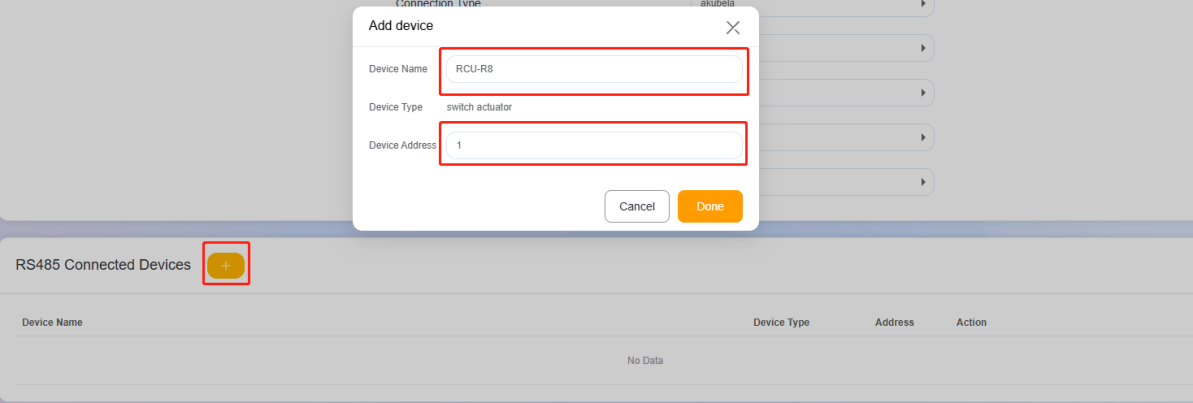
NOTE:
If multiple switch actuators are used, each device must have a unique address.
The address mapping between the actuator (binary) and the web portal (decimal) is as follows:
DIP Switch Number
1
2
3
4
5
6
Device Address to be Entered (Binary Value)
1
2
4
8
16
32
To set the device address, add the values of the DIP switches that are toggled ON, and enter the resulting decimal number on the web portal.
Example:
If DIP switches 1, 2, and 3 are ON, enter 7 (1 + 2 + 4 = 7) as the device address on the web portal.
Configure Electronic Doorplates
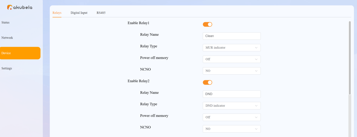
Set Up DND and MUR Indicators
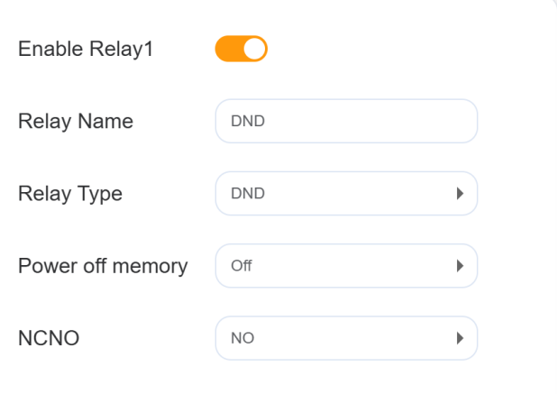
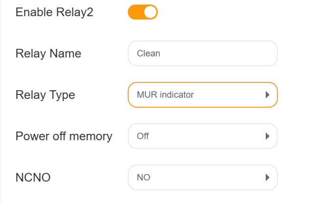
Enable the relays connected to the DND and MUR terminals of the electronic doorplate.
Rename these relays to DND and Clean accordingly.
Set Relay Type to DND and MUR.
Set Power off Memory to OFF.
Set the trigger status NONC to NO.
Save the settings.
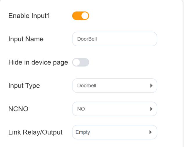
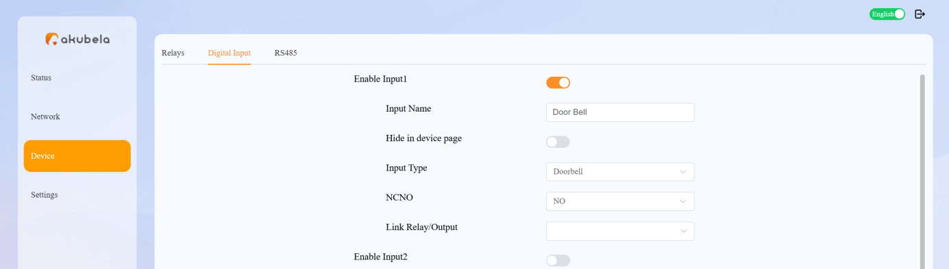
Set Up Doorbell
Enable the Input channel connected to the doorbell terminal of the electronic doorplate.
Rename the input as Doorbell,
Set Input Type to Doorbell.
Set the trigger status NONC to NO.
Save the settings.
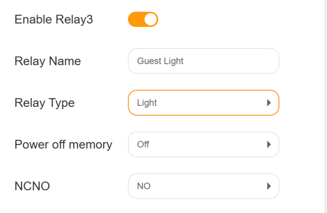
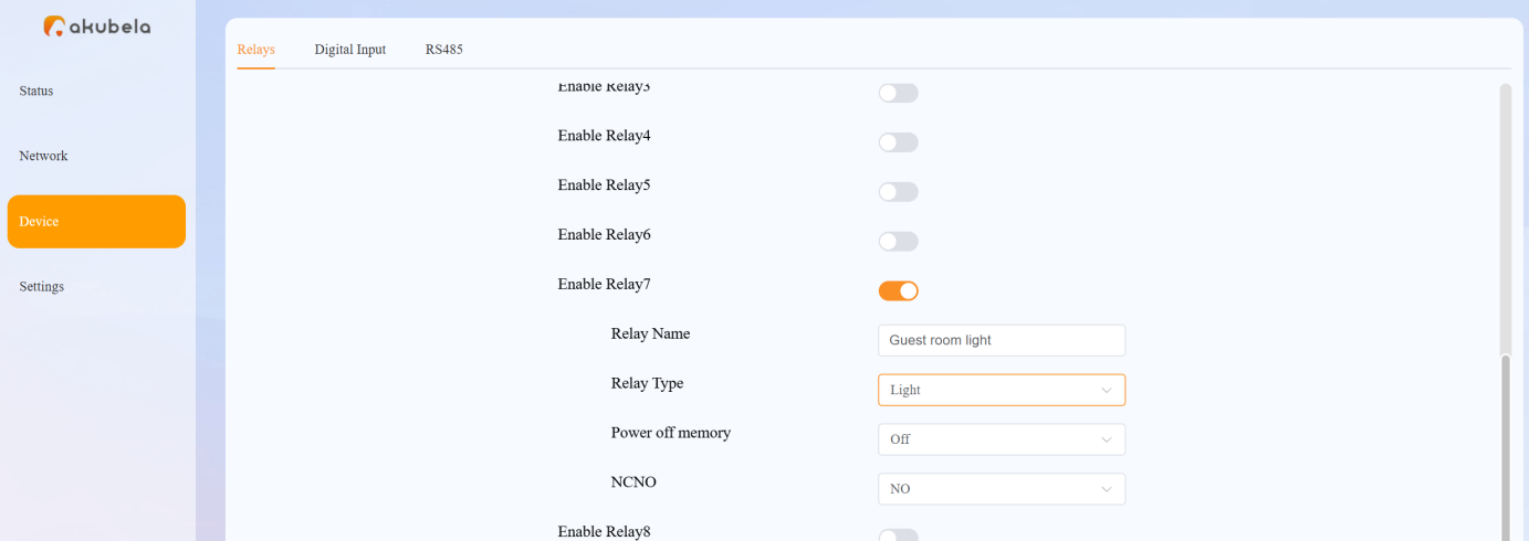
Configure Guest Room Lighting
Enable the relay connected to the light.
Rename the relay as Guest Room Light.
Set Relay Type to Light.
Set Power off Memory to OFF.
Set the trigger status NONC to NO.
Save the settings.
Add the IP-485 Multifunctional Gateway
Ensure the gateway and the home center device are connected to the same LAN.
On the HyPanel Pro, tap Location, select a room, and tap +. The HyPanel Pro will automatically search for nearby devices.
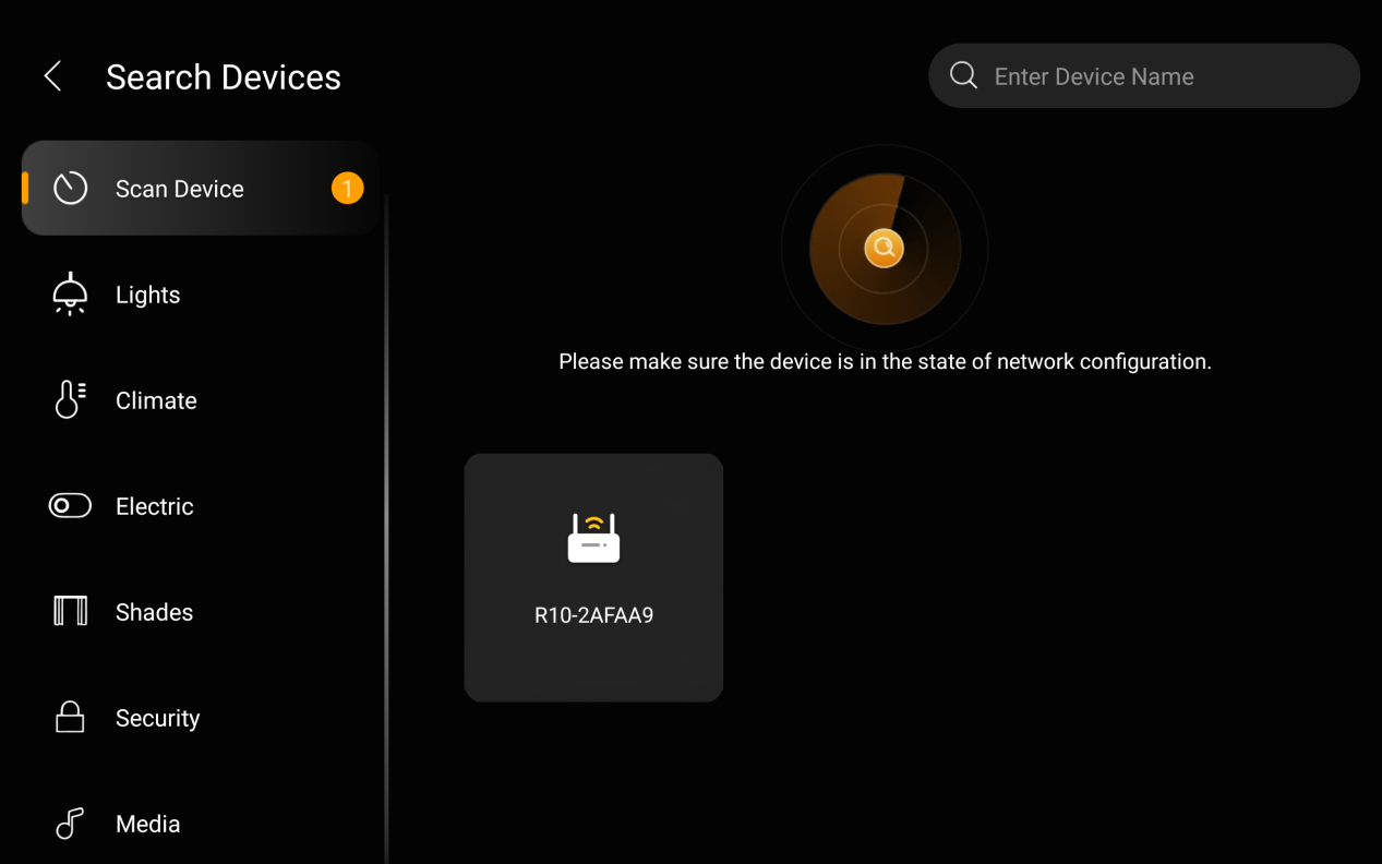
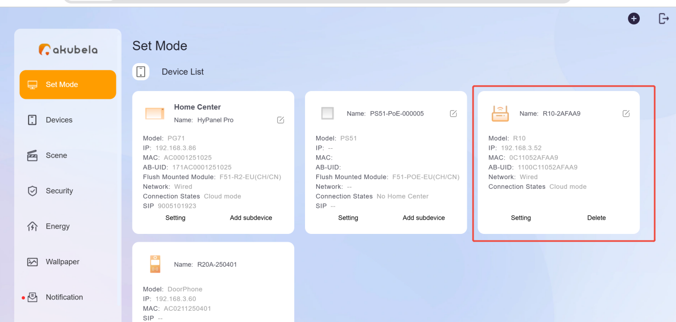
After the R10 is added, log in to the home center’s device web portal and click Settings on the R10 device card to configure its connected devices.
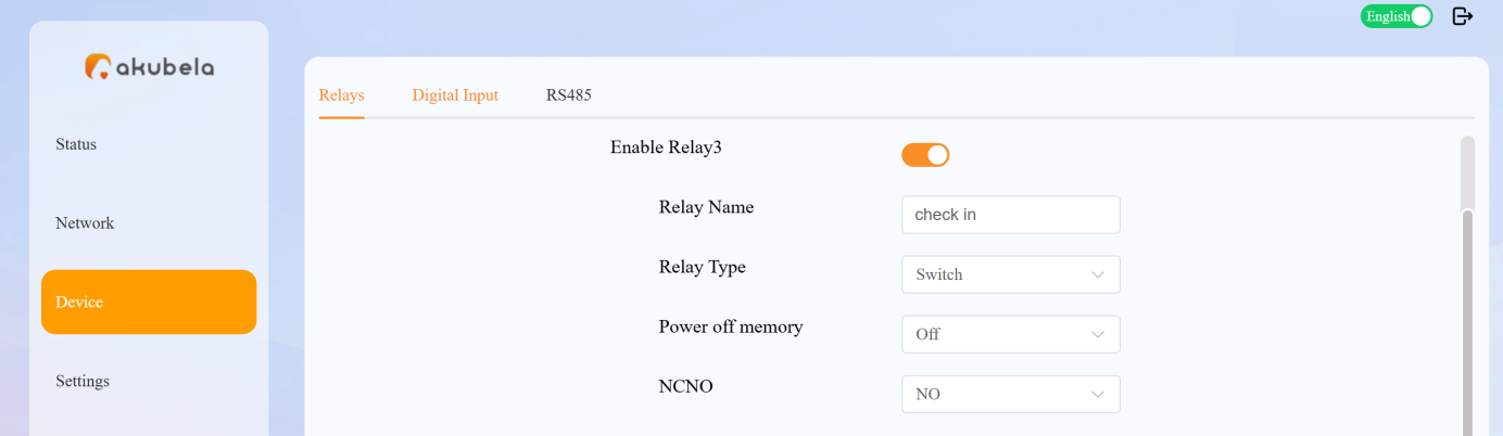
Configure Electronic Doorplates
Set Up Check-in Status Indicator
Go to Device > Relays, and enable the relay connected to the Check-in terminal of the electronic doorplate.
Rename the relay as Check in.
Set Relay Type to Switch.
Set Power off Memory to OFF.
Set the trigger status NCNO to NO.
Save the settings.
Set Up DND and MUR Indicators
Enable the relays connected to the DND and MUR terminals of the electronic doorplate.
Rename these relays to DND and Clean accordingly.
Set Relay Type to DND Indicator and MUR Indicator.
Set Power off Memory to OFF.
Set the trigger status NONC to NO.
Save the settings.
Doorbell Setting
Enable the Input channel connected to the doorbell terminal of the electronic doorplate.
Rename the input as Doorbell,
Set Input Type to Doorbell.
Set the trigger status NONC to NO.
Save the settings.
Configure Guest Room Lighting
Enable the relay connected to the light.
Rename the relay as Guest Room Light.
Set Relay Type to Light.
Set Power off Memory to OFF.
Set the trigger status NONC to NO.
Save the settings.
Function Settings
Scene Configuration
Scenes must be configured in the BelaHome app or the User Web Portal.
After configuration, scenes will automatically sync to the H5 interface.
For detailed instructions, see Create automation scenes.
HyPanel Display Configuration
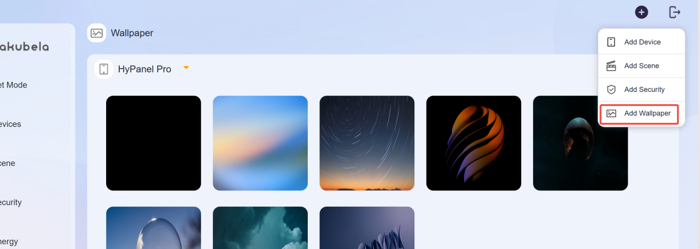
Screen Saver
Log in the home center’s device web portal, click Add Wallpaper and upload the desired image.
Lock Screen Configuration
To prevent guests from accidentally modifying system functions on the HyPanel device, enable the following settings:
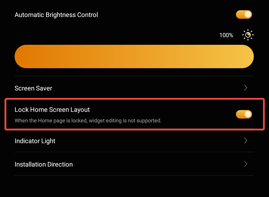
Go to Settings > Display, and enable Lock Home Screen Layout.
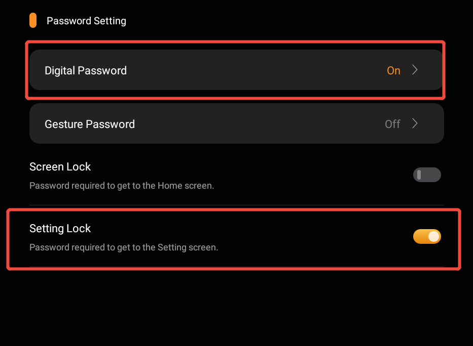
Go to Settings > System Lock, enable Setting Lock, and set a digital password.
Voice Assistance
Voice assistant configuration must be performed room by room.
If you wish to use a voice assistant, refer to the integration guides:
Google Home: https://knowledge.akuvox.com/docs/integrate-akubela-with-google-home
Apple HomeKit: https://knowledge.akuvox.com/docs/integrate-akubela-with-apple-homekit
Amazon Alexa: https://knowledge.akuvox.com/docs/integrate-akubela-with-amazon-alexa
Room Management
NOTE:
A room cannot be checked in or out until all its devices are installed and connected to the cloud.
View Room and Device Data
View dashboard overview
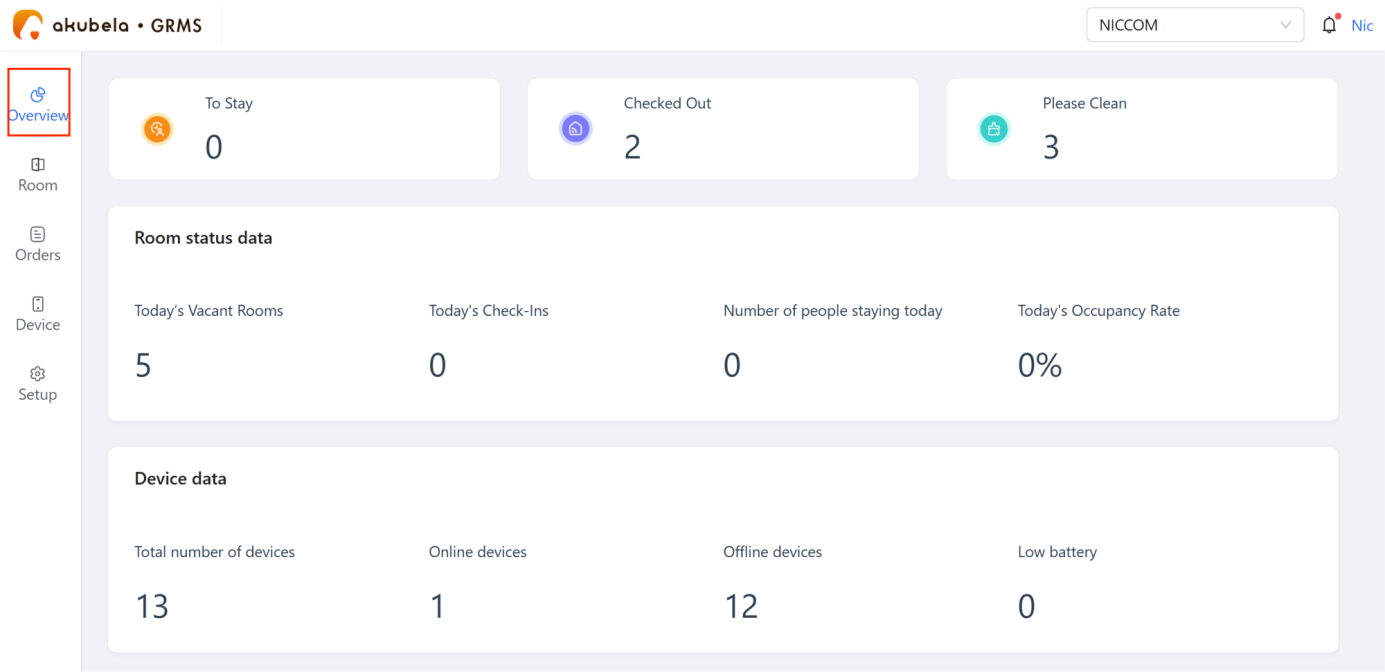
Go to Overview. The dashboard displays the following information.
To Stay | Scheduled check-ins today | |
Checked Out | Check-outs completed today | |
Please Clean | Rooms awaiting cleaning | |
Room status data | Today’s Vacant Rooms | Available rooms |
Today’s Check-Ins | Number of completed check-ins today | |
Number of people staying | Current guest count | |
Today’s Occupancy Rate | Today’s room occupancy percentage | |
Device data | Total number of devices | Total installed devices |
Online devices | Devices currently connected | |
Offline devices | Devices not connected | |
Low battery | Devices with low battery alerts |
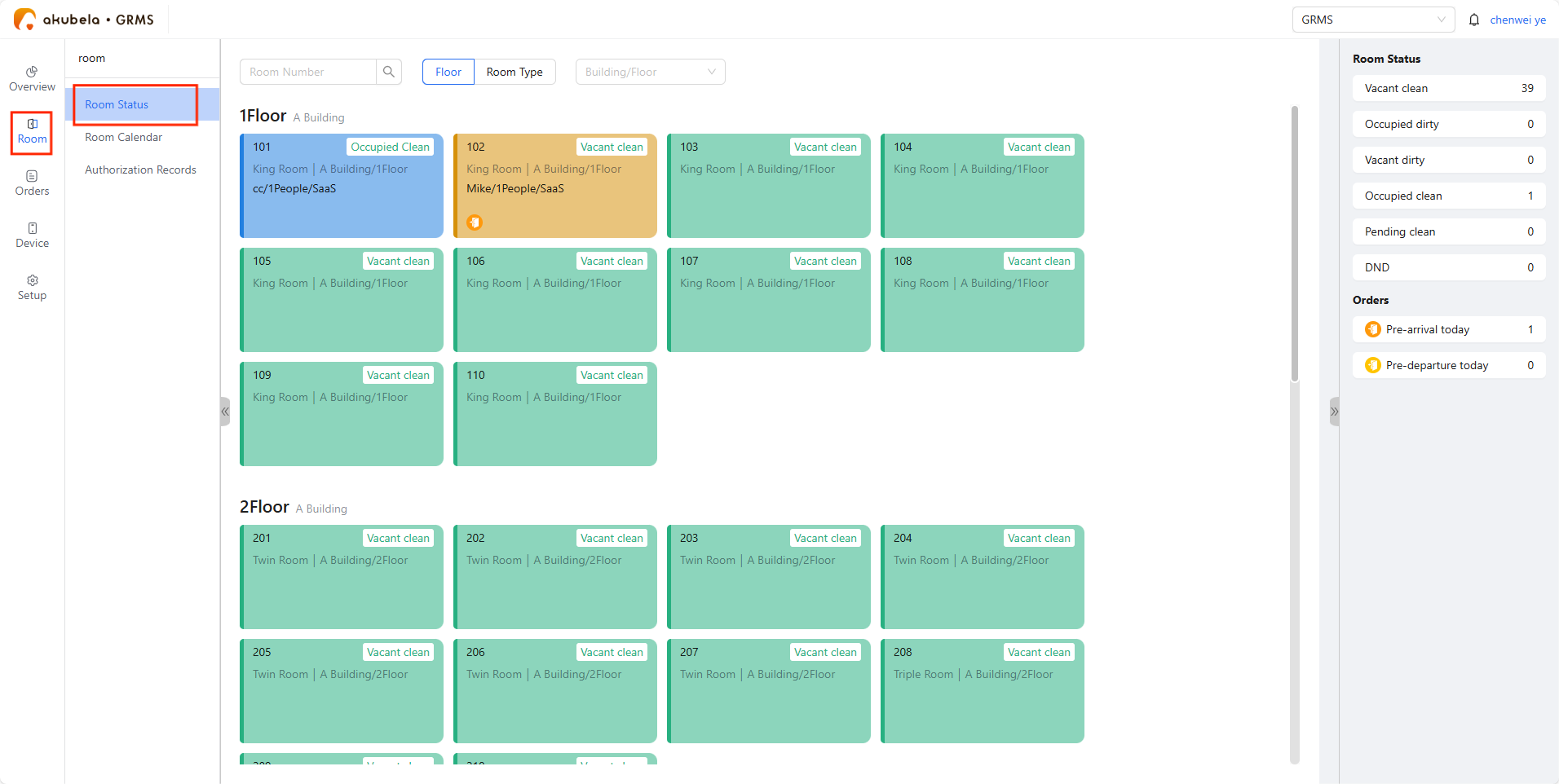
View room status
Go to Room > Room Status. The room card color indicates its current status:
Green: Vacant&ready, available for booking
Blue: Occupied
Yellow: Reserved, not yet checked in
You can also check room status on the Room > Room Calendar.
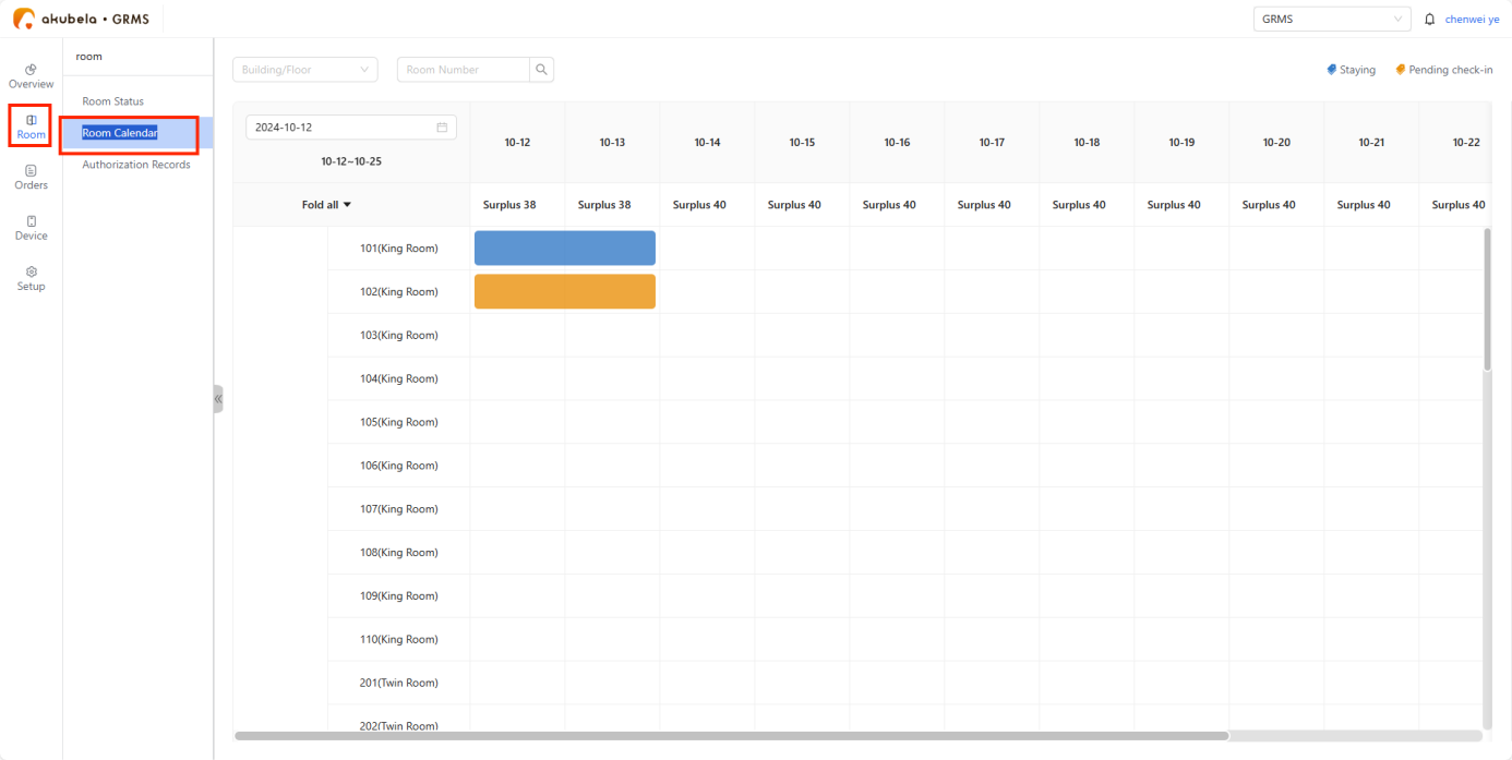
Check-In and Check-Out
You can check guests in and out from either the Room Status or the Room Calendar page.
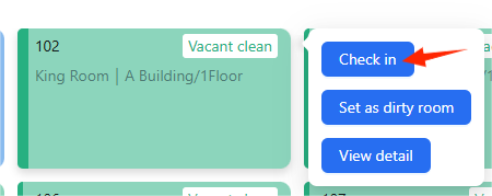
Check-in
Hover over a green vacant room card and click Check in.
Select check-in and check-out times, then fill in the guest’s details.
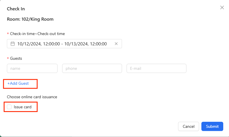
Click Add Guest to include any accompanying people.
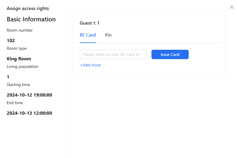
To issue room access cards or grant access permissions, click Issue Card. You can add 2 RF cards and create 6-digit smart lock codes per room.
NOTE:
The access credentials become active at check-in and expire automatically at check-out. If the guest checks out early, all access credentials will be immediately disabled.
Check-out
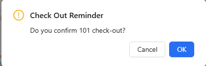
Hover over the room card and click Check Out.
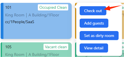
Click OK to confirm. The room status will automatically change to “Vacant Dirty”.
TIP:
From the Room Status page, you can also:
The Room Calendar page allows you to:
Choose specific dates and rooms and make reservations
Enter guest information
Assign access permissions
For more instructions, see GRMS user guide.
View Access Authorization Records
Go to Room > Authorization Records to view all guest access permission records.

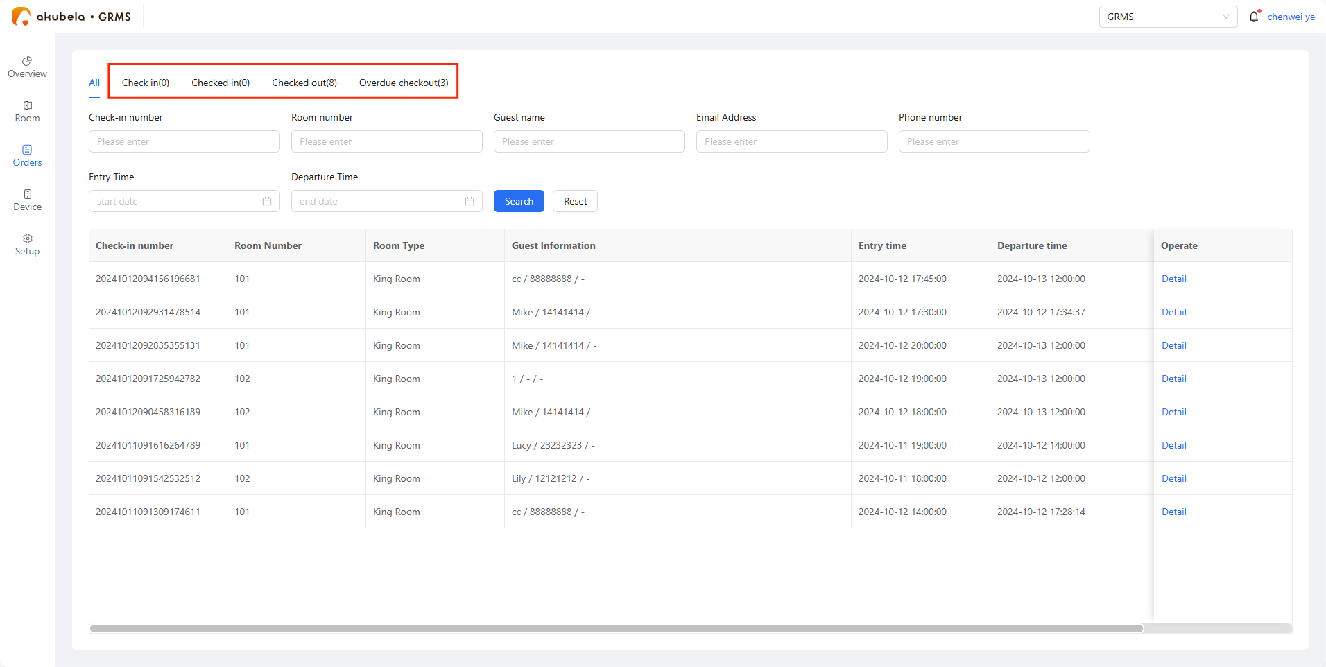
Check Room Orders
Go to the Orders page to search by guest’s name, booking number, or other details. Click Detail to see order information.
Order statuses include:
Check In: Awaiting guest check-in
Checked In: Guest has already checked in
Checked Out: Checked out manually and automatically
Overdue Checked Out: Automatically checked out after stay expired
Manage Devices
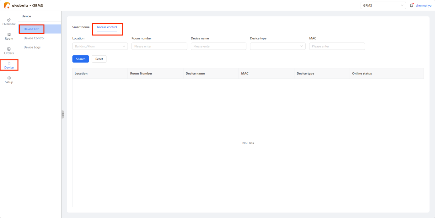
To check smart home devices, devices connected to switch actuator, and wired devices in guest rooms, go to Device > Device List > Smart Home.
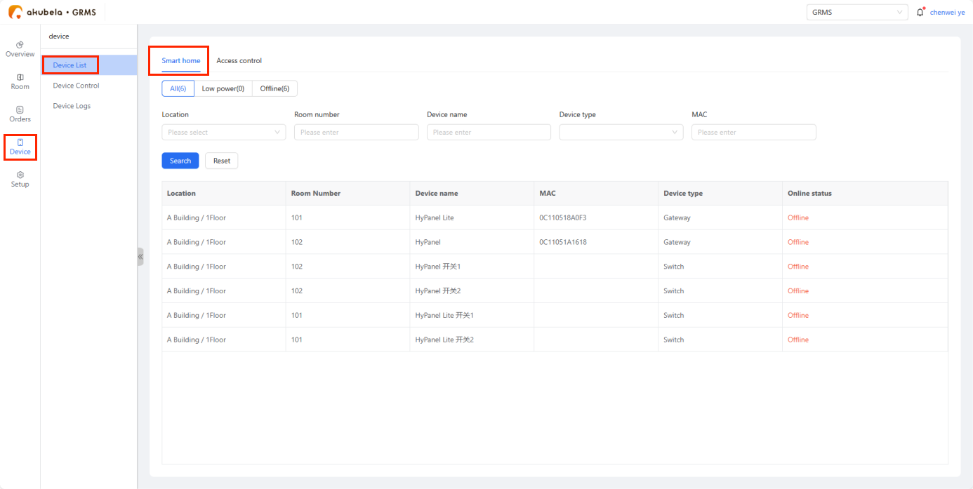
To check door phones and access control devices, go to Device > Device List > Access Control.
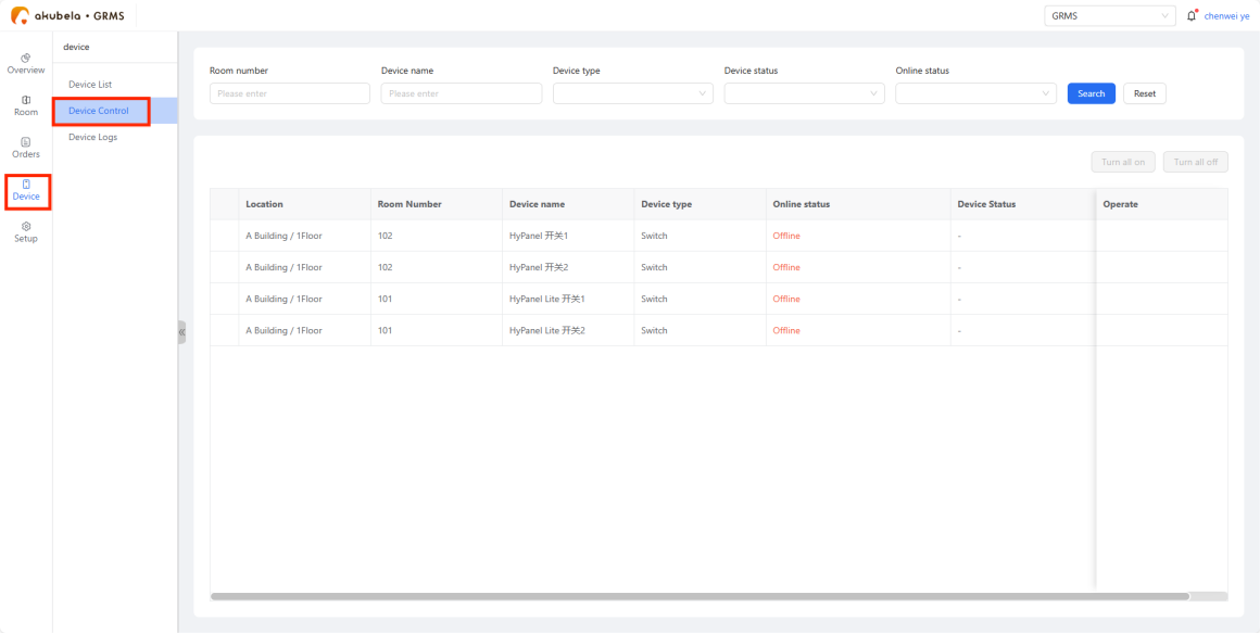
To remotely control smart devices in rooms, go to Device > Device Control.
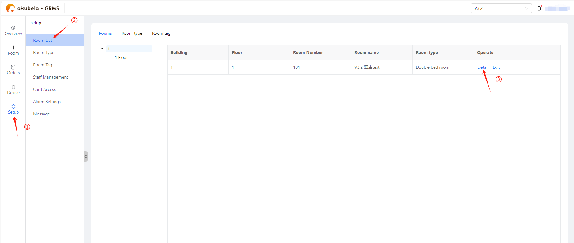
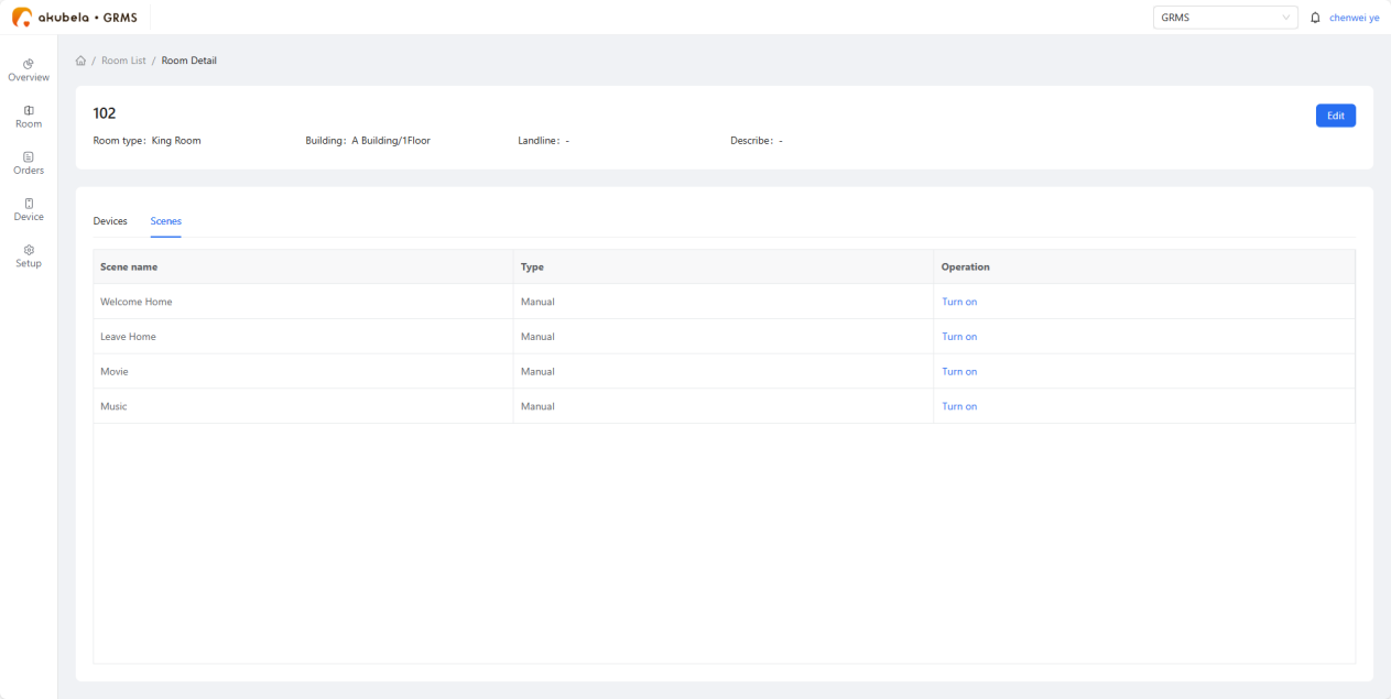
Or click the specific room card and go to Setup > Room List > Detail.
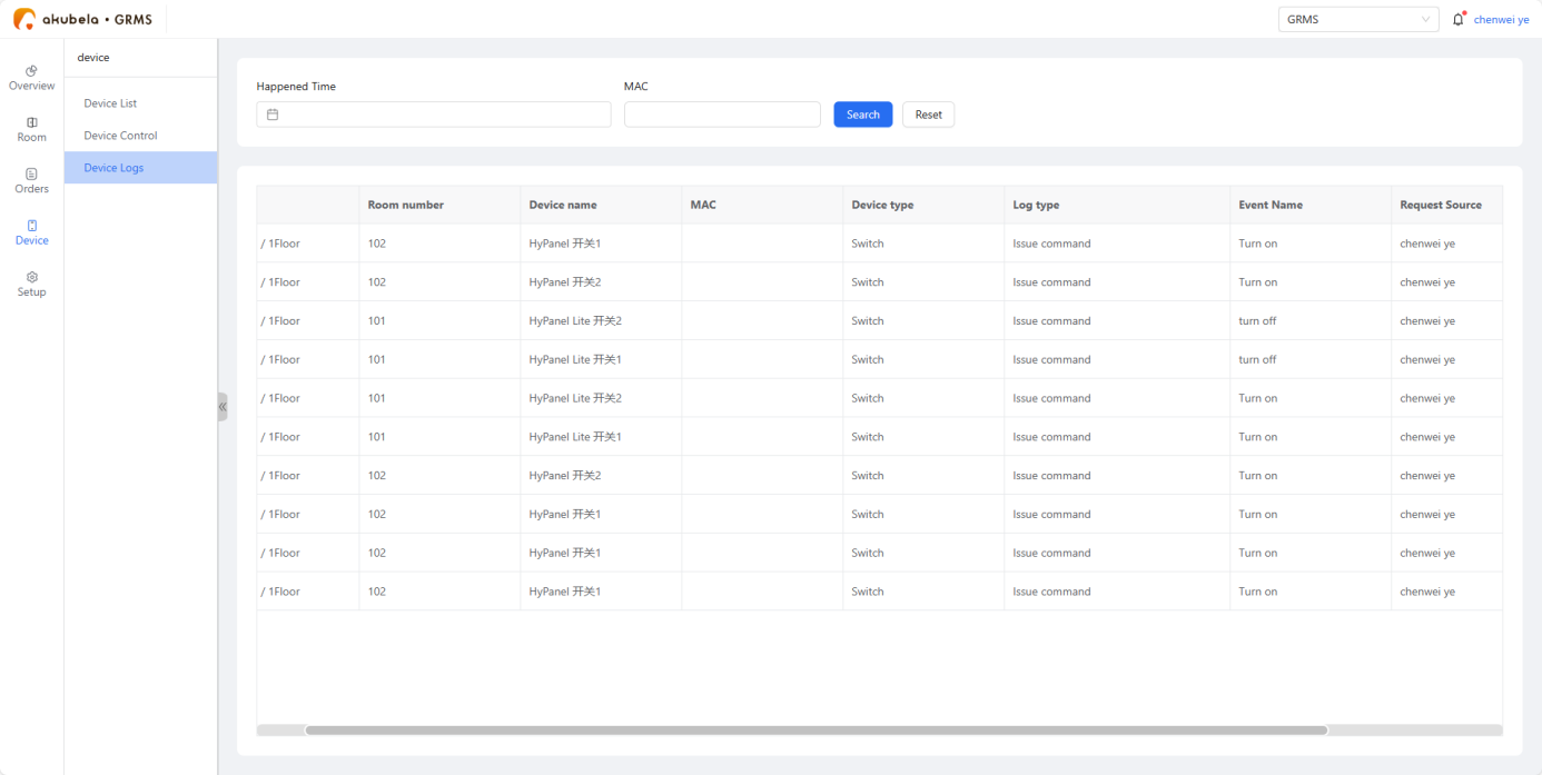
To view device logs, go to Device > Device Logs.
To view room service request and device alarms, go to Setup > Message.
Room Guests Usage
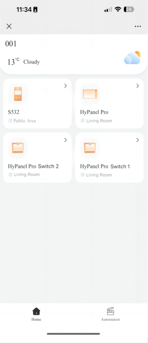
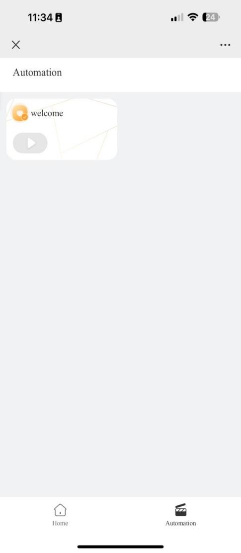
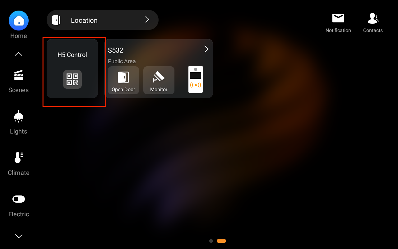
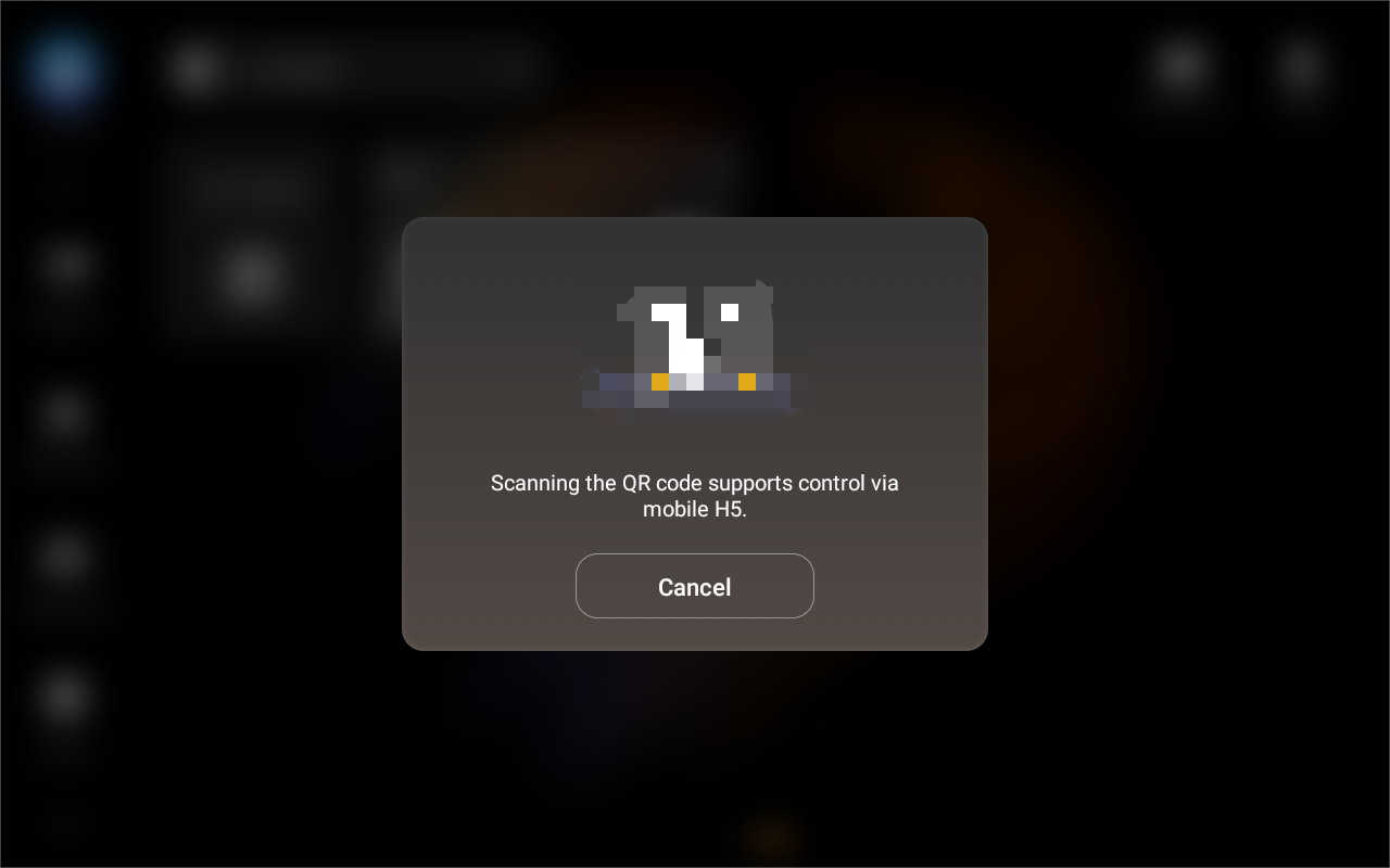
After check-in, an H5 QR code will be displayed on the HyPanel Pro. Guests can scan it to access the H5 interface and control in-room devices.
H5 QR code display screen:
H5 interface: