
Fig.5.7 “ECG setting” Interface
Parameter “Number of ECGs”
This parameter sets the number of ECGs.
Options:
None
1
2
...
64
NOTE:
Set this parameter according to the actual number of installed ECGs. Any configured ECG that is not physically connected will be flagged as faulty. It is recommended to activate only the ECGs that are in use.
ECGs included in a group must also be activated through this parameter; their control behavior, however, will follow the group’s configuration.
5.7.1 Parameter Window ”ECG X”(X=1~64)
The parameter setting interface “ECG X” is shown in Figure 5.7.1. This interface is used for configuring the control of a single DALI device.
Each channel of the KNX/DALI gateway supports up to 64 DALI devices. Each device can be individually controlled for switching, dimming, brightness, colour temperature, and colour settings. Additionally, the gateway provides functions such as operating hour calculation and burn-in mode for each DALI device.

Fig.5.7.1 “ECG X”(X=1~64) Interface
Parameter “Description (max. 30 char)”
This parameter is used to input the ECG name (up to 30 characters).
Parameter “ECG type”
This parameter defines the type of ECG being used..
Options:
LED Module: ECG type DT6, e.g. fluorescent light. Configure parameters in section 5.7.1.1.
ECG with colour control: ECG type DT8, supportscolour control. Configure parameters in section 5.7.1.1, and colour setting parameters in section 5.7.2.
Relays module: ECG type DT7, relay-controlled switch. Only supported in database versions 2.0 or above and DCA versions 2.0.0.1 or above. Configure parameters in section 5.7.1.1.
Self-Contained Battery light (non-switchable): ECG type DT1, without control or status communication objects for switching, brightness, etc.
NOTE:
Only compatible with DALI Class D emergency lighting devices.
DALI defines four types of self-contained emergency devices (A, B, C, D):
A: Switch remains dimmable; light can be dimmed or turned off when power is present; light is on when power is absent.
B: Switch is non-dimmable; light can be turned on/off when power is present; light is on when power is absent.
C: Light remains on at all times regardless of power presence.
D: Non-maintainable; light is on only when power is absent or in test mode. This type is is only suitable for versions with database versions of 2.0 or above, and DCA versions of 2.0.0.1 or above. Set parameters in section 5.7.1.2.
5.7.1.1 Parameter Setting ”LED Module/ECG with colour control/Relays module”
This section only describes the parameter settings only when the ECG type is LED Module/ECG with colour control/Relays module.
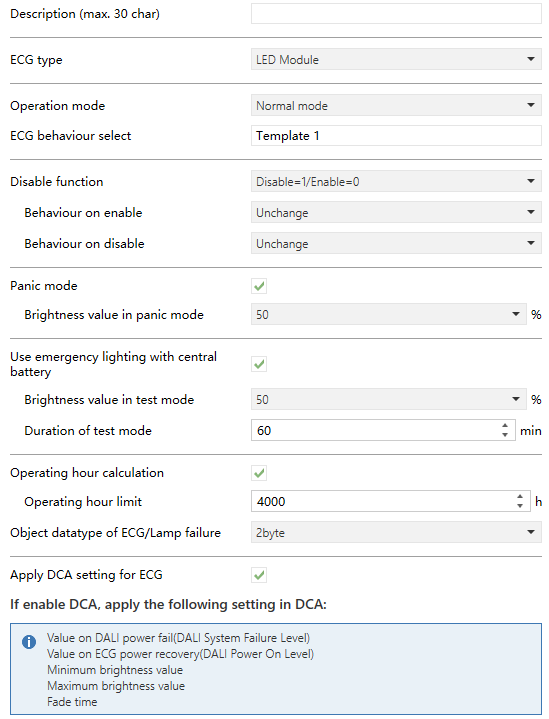
Fig.5.7.1 “LED Module/ECG with colour control/Relays module” Interface
Parameter “Operating mode”
This parameter setting the operating mode of the group.
Options:
Normal mode: Common switch control of the lights, including switching, dimming, and setting brightness for the DALI devices in the group.
Permanent mode: The DALI device in the group outputs with a fixed brightness value; the brightness cannot be switched or changed.
Normal/Night mode: In normal mode, control is the same as Normal mode. In night mode, the light can either turn off after a delay or maintain a fixed brightness. Night mode is activated via Object 2.
Staircase mode: Activates staircase lighting, which automatically turns off after a set delay.
TIP:
For detailed descriptions of each mode, see sections 5.6.1.1 ,5.6.1.2, 5.6.1.3 and 5.6.1.4.
Parameter “ECG behaviour select”
This parameter sets the behavior of the ECG, which is achieved by recalling the settings of the template.
Options:
Template 1
...
Template 8
Parameter “Disable function”
This parameter sets the disable/enable control for the ECG.
Options:
Disable
Disable=1/Enable=0
Disable=0/Enable=1
When enabled, the following parameters are visible.
- Parameter “Behaviour on enable”
This parameter sets the behavior when the ECG is enabled.
Options:
Unchange: ECG output remains unchanged.
Switch on: ECG output executes the switch on operation.
Switch off: ECG output executes the switch off operation.
- Parameter “Behaviour on disable”
This parameter sets the behavior when the ECG is disabled.
Options:
Unchange: ECG output remains unchanged.
Switch on: ECG output executes the switch on operation.
Switch off: ECG output executes the switch off operation.
Parameter “Panic mode”
This parameter sets whether to enable the function of panic mode. When enabled, the panic mode can be activated via object.
NOTE:
This function is only supported in database versions 2.0 or above and DCA versions 2.0.0.1 or above.
The following parameter is visible when previous parameter is selected to enable.
- Parameter “Brightness value in panic mode”
Set the brightness value in panic mode.
When panic mode is active, the light maintains this brightness level and cannot be witched or adjusted. Group assignments are temporarily canceled, and scenes will not be recalled. Once panic mode is deactivated, the device returns to its previous brightness or the defined on/off value and can be controlled individually or reassigned to a group.
Options:
0%
1%
2%
...
100%
Parameter “Use emergency lighting with central battery”
This parameter sets whether to use the emergency lighting with central battery. When enabled, a test mode can be triggered via an object to test the discharge time and capacity of the central battery.
Any ECG type (except Self-Contained Battery light) can be configured as emergency lighting, even if the ECG is assigned to a group.
NOTE:
This function is only supported in versions with database version 2.0 or above, and DCA version 2.0.0.1 or above.
The following parameter is visible when previous parameter is selected to enable.
- Parameter “Brightness value in test mode”
Set the brightness value in test mode.
When test mode is activated, the light maintains the set brightness and cannot be switched or adjusted. Group assignments are temporarily canceled, and scenes will not be recalled during the test.
When test mode ends, the group and scene configurations are reprogrammed to the ECG, and normal control resumes. If the gateway loses power during test mode, any untested ECGs remain in standby after power recovery. Test mode must be reactivated manually.
After normal completion of test mode, the device returns to its previous brightness or the defined on/off setting and can again be individually controlled or reassigned to a group.
Options:
0%
1%
2%
...
100%
- Parameter “Duration of test mode”
This parameter is visible when previous parameter is selected to enable. Used to set duration of test mode.
Options: 5..255 min
Parameter “Operating hour calculation”
This parameter setting whether to enable operation hour calculation function.
The following parameter is visible when the previous parameter is enabled.
- Parameter “Operating hour limit”
Set the limit value of the light operation hour. When the operation hour of the light reaches the limit value, the object "Life time exceeded" sends an alarm to the bus.
Options: 0..200000h
NOTE:
The operation hours are recorded every 5 minutes.
If the bus loses power, the recording may be slightly inaccurate because the power-off period may prevent the last interval from being saved. As a result, the operation hour may have a minor discrepancy of a few minutes.
Parameter “Object datatype of ECG/light failure”
This parameter setting the object datatype of the ECG/light failure.
Options:
bit: No distinction between failure types. Any failure (light or ECG) triggers a telegram with value “1” to the bus.
1byte: Distinguish failure types including bit7-ECG failure; bit6- light failure; bit5-bit0. ECG number: 1..64.
2byte: Distinguish failure types. Bit 8 is 1 for light failure; bit 9 is 1 for ECG failure; bit 10 is 1 for Converter failure.
The 1 byte object value is defined as follows:
Bit 6 | Bit 5 | Bit 4 | Bit 3 | Bit 2 | Bit 1 | Bit 0 | |
ECG failure | light failure | ECG number1..64 | |||||
Example:
This object can also be used to query the light and ECG failure. When the highest two bit value, both Bit7 and Bit6, of the telegram received by the object are 1, indicating to query the ECG x failure, such as: Query the failure status of ECG3: 1100 0010 (object value 194) If the ECG of ECG3 is faulty, the gateway will respond: 1000 0010 (object value 130) | |||||||
The 2 byte object value is defined as follows:
Bit 11...Bit15 | Bit 10 | Bit 9 | Bit 8 | Bit 7 | Bit 0-Bit 5 | |
0 | 0: No error 1: Converter failure | 0: No error 1: ECG failure | 0: No error 1: light failure | 0: Response or spontaneous sending 1: Read | 0: Device address 1: Group address | DALI device address :1...64 DALI group address: 0...15 |
TIP:
Light failure: One or more fixtures are not working (damaged) or not connected.
ECG failure: One or more ballasts on the DALI gateway output are not working or not connected.
Parameter “Apply DCA setting for ECG”
This parameter sets whether apply DCA setting for ECG. When enabled, The gateway executes operations according to the DCA settings (e.g., values on DALI power recovery, values on DALI power failure, dimming time, etc.) and ignores ETS settings.


5.7.1.2 Parameter Setting “Self-Contained Battery light (non-switchable)”
This section describes parameter settings applicable only when the ECG type is Self-Contained Battery Light (Non-Switchable).

Fig.5.7.3 “Self-Contained Battery light (non-switchable)” Interface
Parameter “Emergency mode behaviour select”
This parameter defines the behavior of the emergency mode by recalling the settings of a selected template.
Options:
Template 1
...
Template 8
When the emergency light is activated for emergency mode, function test, or duration test, it will follow the behavior configured in the selected template.
In the event of ECG power failure or disconnection, the light automatically switches to emergency mode. After power recovery, it returns to normal operation after a delay.
Parameter “Object datatype of ECG/light failure”
This parameter defines the object datatype for reporting ECG/light failures..
Options:
1bit
1byte
2byte
TIP:
The detailed explanation of each datatype is the same as described in section 5.7.1.1.
5.7.2 Parameter Window ”Colour control”
This interface is visible when “ECG with colour control” is selected as the ECG type.

Fig.5.7.2 “Colour control”
Parameter “Colour control type”
This parameter sets the colour control type for the ECG.
Options:
Colour Temperature: Cool-warm colour control.
RGB Colour: Three RGB colours control.
RGBW Colour: Four RGBW colours control
XY Colour: Controls color in a color space using two specified coordinates.
5.7.2.1 Colour Control Type “Colour Temperature”

Fig.5.7.2.1 “Colour Temperature”
Parameter “Object datatype of colour temperature”
This parameter sets the object datatype of colour temperature.
Options:
1byte relative percentage value
2byte absolute value
Parameter “Behaviour when switch on”
This parameter sets the colour temperature value when the ECG switch is on.
Options:
Via ETS parameter: The colour temperature when the ECG object "Switch" on is set by the next parameter.
Last colour temperature value: The colour temperature when the ECG object "Switch" on follows the last saved colour temperature value. If the value is undefined, the default colour temperature is 4000K and brightness is 50%.
The following parameter is visible when “Via ETS parameter” is selected.
- Parameter“colour temperature when switch on”
Set the colour temperature when light is switch on.
Options: 1000...10000K
Parameter “Colour temperature on DALI power fail (DALI System Failure Level)”
This parameter sets the colour temperature value of the light after the DALI bus is powered off. This value is saved in ECG, and ECG automatically changes the output of the colour temperature value in the event of power off.
Options:
3000 K
3500 K
4000 K
4500 K
5000 K
5500 K
6000 K
6500 K
Unchange: The output color temperature remains at its value prior to the DALI bus power-off; in other words, the light’s color temperature does not change.
NOTE:
This feature is supported only on database versions 2.0 or higher and DCA versions 2.0.0.1 or higher.
Parameter “Colour temperature on ECG power recovery (DALI Power On Level)”
This parameter sets the colour temperature value of the light after ECG power-on reset. This value will be saved in the ECG, and the ECG will output the colour temperature value when the ECG is powered on and reset.
Options:
3000 K
3500 K
4000 K
4500 K
5000 K
5500 K
6000 K
6500 K
Value before failure: The output colour temperature value is the colour temperature value before the ECG is power recovery.
NOTE:
This feature is supported only on database versions 2.0 or higher and DCA versions 2.0.0.1 or higher.
Parameter “Minimum physical colour temperature (refer to the technical spec. Of warm white)”
Parameter “Maximum physical colour temperature control (refer to the technical spec. Of warm white)”
These parameters define the minimum and maximum physical color temperature of the ECG output, corresponding to the inherent color temperature range of the light, typically for warm and cool white LEDs.
Options:
1000...10000K
NOTE:
The minimum color temperature must always be lower than the maximum. If this condition is not met, the ETS will not accept the settings.

Parameter “Minimum colour temperature control”
Parameter “Maximum colour temperature control”
These parameters define the minimum and maximum controllable color temperature of the ECG output, representing the range that the DALI Gateway can set for the lights.
Options: 1000...10000K
NOTE:
The minimum color temperature must always be lower than the maximum. If this condition is not met, ETS will not accept the settings.

Parameter “Dimming time via colour relative dimming”
Within the maximum colour temperature range, this parameter defines the dimming time via colour relative dimming.
Options: 1...255s
Parameter “Allow switch on via relative dimming”
This parameter defines whether the light can be switched on via relative dimming.
Parameter “Allow switch on via set colour temperature”
This parameter defines whether the light can be switched on via set colour temperature.
Parameter “Allow switch on via colour relative dimming”
This parameter defines whether the light can be switched on via relative dimming.
5.7.2.2 Colour Control Type “RGB colour”
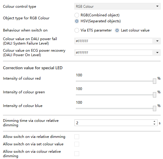
Fig.5.7.2.2 “RGB colour ”
Parameter “Object type for RGB colour”
This parameter sets the object datatype of RGB colour.
Options:
RGB(Combined object)
HSV(Separated objects)
Parameter “Behaviour when switch on”
This parameter sets the colour value when the ECG switch is on.
Options:
Via ETS parameter: The colour value when the ECG object "Switch" on is set by the next parameter.
Last colour value: The colour value when the ECG object "Switch" on follows the last saved colour value. If the value is uncertain, the default colour is white with 50% brightness.
The following parameter is visible when “Via ETS parameter” is selected.
- Parameter“colour value when switch on”
Set the colour value when light is switch on.
Options: 000000...FFFFFF
Parameter “Colour value on DALI power fail (DALI System Failure Level)”
This parameter sets the colour value of the light after the DALI bus is powered off. This value is saved in ECG, and ECG automatically changes the output of the colour value in the event of power off.
Options:
#FFFFFF White
#7F7F7F Gray
#FF0000 Red
#00FF00 Green
#0000FF Blue
#FFFF00 Yellow
#00FFFF Cyan
#FF00FF Purple
Unchange: The output color value remains the same as before the DALI bus power-off; in other words, the light color does not change.
NOTE:
This function is only supported in database versions 2.0 or above and DCA versions 2.0.0.1 or above.
Parameter “Colour value on ECG power recovery (DALI Power On Level)”
This parameter sets the colour value of the light after ECG power-on reset. This value will be saved in the ECG, and the ECG will output the colour value when the ECG is powered on and reset.
Options:
#FFFFFF White
#7F7F7F Gray
#FF0000 Red
#00FF00 Green
#0000FF Blue
#FFFF00 Yellow
#00FFFF Cyan
#FF00FF Purple
Value before failure: The output color value is restored to the value it had before the ECG lost power.
NOTE:
This function is only supported in database versions 2.0 or above and DCA versions 2.0.0.1 or above.
Correction value for special LED
Parameter“Intensity of colour red”
Parameter“Intensity of colour green”
Parameter“Intensity of colour blue”
These parameters set the intensity of colour red/green/blue.
Options: 0...100%
NOTE:
If Intensity is set to 0%, the control for this colour is disabled and the colour output will be 0%.
Parameter “Dimming time via colour relative dimming”
This parameter is visible when “HSV(Separated objects)” is selected. Within the maximum intensity range of colour, it used to define the dimming time via colour relative dimming.
Options: 1...255s
Parameter “Allow switch on via relative dimming”
This parameter defines whether to allow the light switch on via relative dimming.
Parameter “Allow switch on via set colour value”
This parameter is visible when “HSV (Separated objects)” is selected. Used to define whether to allow the light switch on via set colour value.
Parameter “Allow switch on via colour relative dimming”
This parameter is visible when “HSV (Separated objects)” is selected. Used to define whether to allow the light switch on via colour relative dimming.
5.7.2.3 Colour Control Type “RGBW colour”
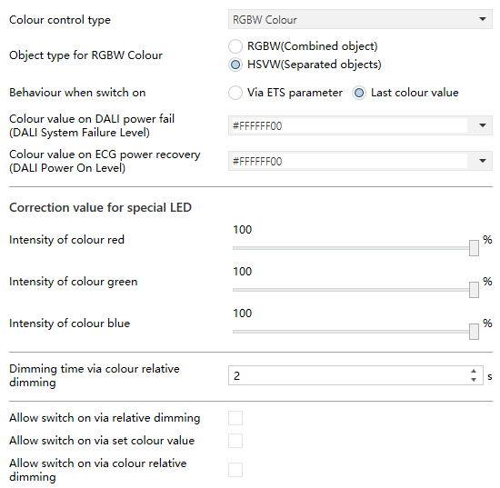
Fig.5.7.2.3 “RGBW colour”
Parameter “Object type for RGBW colour”
This parameter sets the object datatype of RGBW colour .
Options:
RGBW(Combined object)
HSVW(Separated objects)
Parameter “Behaviour when switch on”
This parameter sets the colour value when the ECG switch is on.
Options:
Via ETS parameter: The colour value when the ECG object "Switch" turns on is set by the next parameter.
Last colour value: The colour value when the ECG object "Switch" turns on follows the last saved colour value. If the value is undefined, the default colour is white and “W” value is 50%.
The following parameters are visible when “Via ETS parameter” is selected:
- Parameter “Colour value when switch on”
This parameter sets the colour value when switch on.
Options: 000000...FFFFFF
- Parameter “Additional White value”
This parameter sets the additional white colour value when switch on.
Options: 0...100%
Parameter “Colour value on DALI power fail (DALI System Failure Level)”
This parameter sets the colour value of the light after the DALI bus is powered off. This value is saved in ECG, and ECG automatically changes the output of the colour value in the event of power off.
Options:
#FFFFFF White
#7F7F7F Gray
#FF0000 Red
#00FF00 Green
#0000FF Blue
#FFFF00 Yellow
#00FFFF Cyan
#FF00FF Purple
Unchange: The output color value remains the same as before the DALI bus power-off; in other words, the light color does not change.
NOTE:
This function is only supported in database versions 2.0 or above and DCA versions 2.0.0.1 or above.
Parameter “Colour value on ECG power recovery (DALI Power On Level)”
This parameter sets the colour value of the light after ECG power-on reset. This value will be saved in the ECG, and the ECG will output the colour value when the ECG is powered on and reset.
Options:
#FFFFFF White
#7F7F7F Gray
#FF0000 Red
#00FF00 Green
#0000FF Blue
#FFFF00 Yellow
#00FFFF Cyan
#FF00FF Purple
Value before failure: The output color value is restored to the value it had before the ECG lost power.
NOTE:
This function is only supported in database versions 2.0 or above and DCA versions 2.0.0.1 or above.
Correction value for special LED
Parameter “Intensity of colour red”
Parameter “Intensity of colour green”
Parameter “Intensity of colour blue”
These parameters set the intensity of colour red/green/blue.
Options:
0...100%
NOTE:
If Intensity is set to 0%, the control for this colour is disabled and the colour output will be 0%.
Parameter “Dimming time via colour relative dimming”
This parameter is visible when “HSVW(Separated objects)” is selected. Within the maximum intensity range of colour, it used to define the dimming time via colour relative dimming.
Options:
1...255s
Parameter “Allow switch on via relative dimming”
This parameter defines whether to allow the light switch on via relative dimming.
Parameter “Allow switch on via set colour value”
This parameter is visible when “HSVW(Separated objects)” is selected. Used to define whether to allow the light switch on via set colour value.
Parameter “Allow switch on via set colour relative dimming”
This parameter is visible when “HSVW(Separated objects)” is selected. Used to define whether to allow the light switch on via colour relative dimming.
5.7.2.4 Colour Control Type “XY colour”
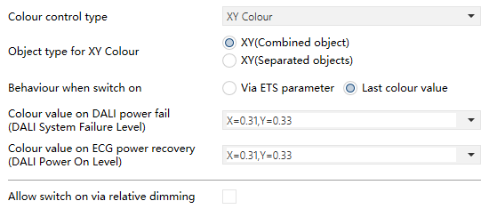
Fig.5.7.2.4 “XY colour”
Parameter “Object type for XY colour”
This parameter sets the object datatype of XY colour.
Options:
XY(Combined object)
XY(Separated objects)
Parameter “Behaviour when switch on”
This parameter sets the colour value when the ECG switch is on.
Options:
Via ETS parameter: The colour value when the ECG object "Switch" turns on is set by the next parameter.
Last colour value: The colour value when the ECG object "Switch" turns on follows the last saved colour value. If the value is uncertain, the default colour is white with 50% brightness.
The following parameters are visible when ”Via ETS parameter” is selected.
- Parameter“colour X-value when switch on”
This parameter sets the colour X-value when switch on.
Options: 0...1
- Parameter“colour Y-value when switch on”
This parameter sets the colour Y-value when switch on.
Options: 0...1
NOTE:
Any control values with coordinates outside the valid color range are considered invalid, for example: 0.01/0.01.
Parameter “Colour value on DALI power fail (DALI System Failure Level)”
This parameter sets the colour value of the light after the DALI bus is powered off. This value is saved in ECG, and ECG automatically changes the output of the colour value in the event of power off.
Options:
X=0.31,Y=0.33 White
X=0.31,Y=0.31 Gray
X=0.64,Y=0.33 Red
X=0.30,Y=0.60 Green
X=0.15,Y=0.06 Blue
X=0.42,Y=0.52 Yellow
X=0.17,Y=0.37 Cyan
X=0.28,Y=0.14 Purple
Unchange: The output color value remains the same as before the DALI bus power-off; in other words, the light color does not change.
NOTE:
This function is only supported in database versions 2.0 or above and DCA versions 2.0.0.1 or above.
Parameter “Colour value on ECG power recovery (DALI Power On Level)”
This parameter sets the colour value of the light after ECG power-on reset. This value will be saved in the ECG, and the ECG will output the colour value when the ECG is powered on and reset.
Options:
X=0.31,Y=0.33 White
X=0.31,Y=0.31 Gray
X=0.64,Y=0.33 Red
X=0.30,Y=0.60 Green
X=0.15,Y=0.06 Blue
X=0.42,Y=0.52 Yellow
X=0.17,Y=0.37 Cyan
X=0.28,Y=0.14 Purple
Value before failure: The output colour value is the colour value before the ECG is power recovery.
NOTE:
This function is only supported in database versions 2.0 or above and DCA versions 2.0.0.1 or above.
Parameter “Dimming time via set colour value”
This parameter defines the dimming time of the XY colour value. That is, the dimming time of the XY value from 0 to 1.
Options: 0...255s
Parameter “Allow switch on via colour relative dimming”
This parameter defines whether to allow the light switch on via relative dimming.