Akuvox indoor monitors can be connected to external relays through MK485 or RSAC-C1-R8, the Akuvox or akubela relay controller. This allows users to conveniently control devices such as lights or curtains by tapping on the indoor monitor or the SmartPlus App.
Note
The following models with specific firmware versions or higher support configuring external relays on the web interface:
S567: 567.30.12.802;
S562: 562.30.14.204;
S563: 563.30.12.902;
S565: 565.30.10.210;
X933: 933.30.13.702;
X937: 937.30.13.122;
C316: 316.30.13.102;
C319: 119.30.12.902;
IT88: 88.30.12.904.
Currently, only the following models with specific versions or higher support configuring akubela RCU inputs on the web interface.
S567: 567.30.114.203;
S565: 565.30.10.324;
S562: 562.30.14.408;
S563: 563.30.14.306;
X937: 937.30.14.306;
X933: 933.30.14.403;
C319: 119.30.14.503;
C316: 316.30.14.607;
IT88: 88.30.14.603.
MK485
Wiring Diagram
The MK485 should be connected to Akuvox indoor monitors via RS485 ports.
It has 8 relay output ports that can connect up to 8 home automation devices.
Connect devices to the C and B ports for a normally open.
Connect devices to the C and A ports for a normally closed.

Configuration on the Web Interface
After correct wiring, you need to configure external relays on the indoor monitor’s web interface.
Use the device IP to log in to its web interface with the username and password. The initials are both admin.
Go to the Device > External Relay interface.
Select Akuvox-MK485-G2R-8J8C V3.0 as the External Relay Type.
Select the External Relay Mode for the indoor monitor to control the external relays.
Enable the desired key and select the relay function.
Set the Hold Delay time that decides how long the relay is activated. Never means it keeps activated once it is triggered.
Customize the Display Name.
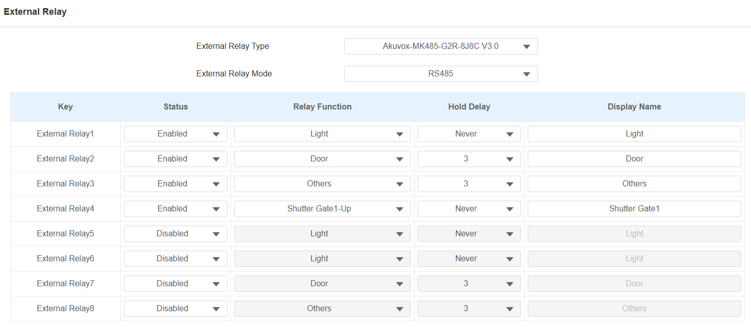
Click Submit.
Configuration on the SmartPlus Cloud
When the indoor monitor is connected to SmartPlus Cloud, you can configure external relays on the SmartPlus Cloud platform.
Users can control smart home devices on their SmartPlus App easily.
Note
The SmartPlus App version should be 7.14.0003(Android)/7.14.3(iOS) or higher.
ONLY single-family and community projects support this feature.
The following models with specific firmware versions or higher support configuring external relays on the cloud:
S565: 565.30.10.505
S562: 562.30.14.609
Take a community project as an example.
Log in to the SmartPlus Cloud platform with an installer account.
Click
 of the target community and go to the apartment where the indoor monitor is installed.
Click
 of the desired resident and scroll to the Intercom Devices section.

Click
to modify the settings.

Turn on the External Device feature.
Set Type to Akuvox MK485.
Select the Mode for the indoor monitor to control the external relays.
Enter the relay name and select its function. You can click Add Relay to add up to 8 relays.
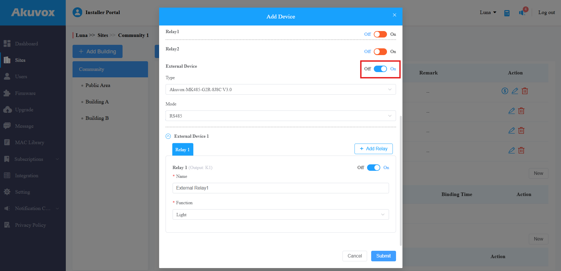
Click Submit to save the settings.
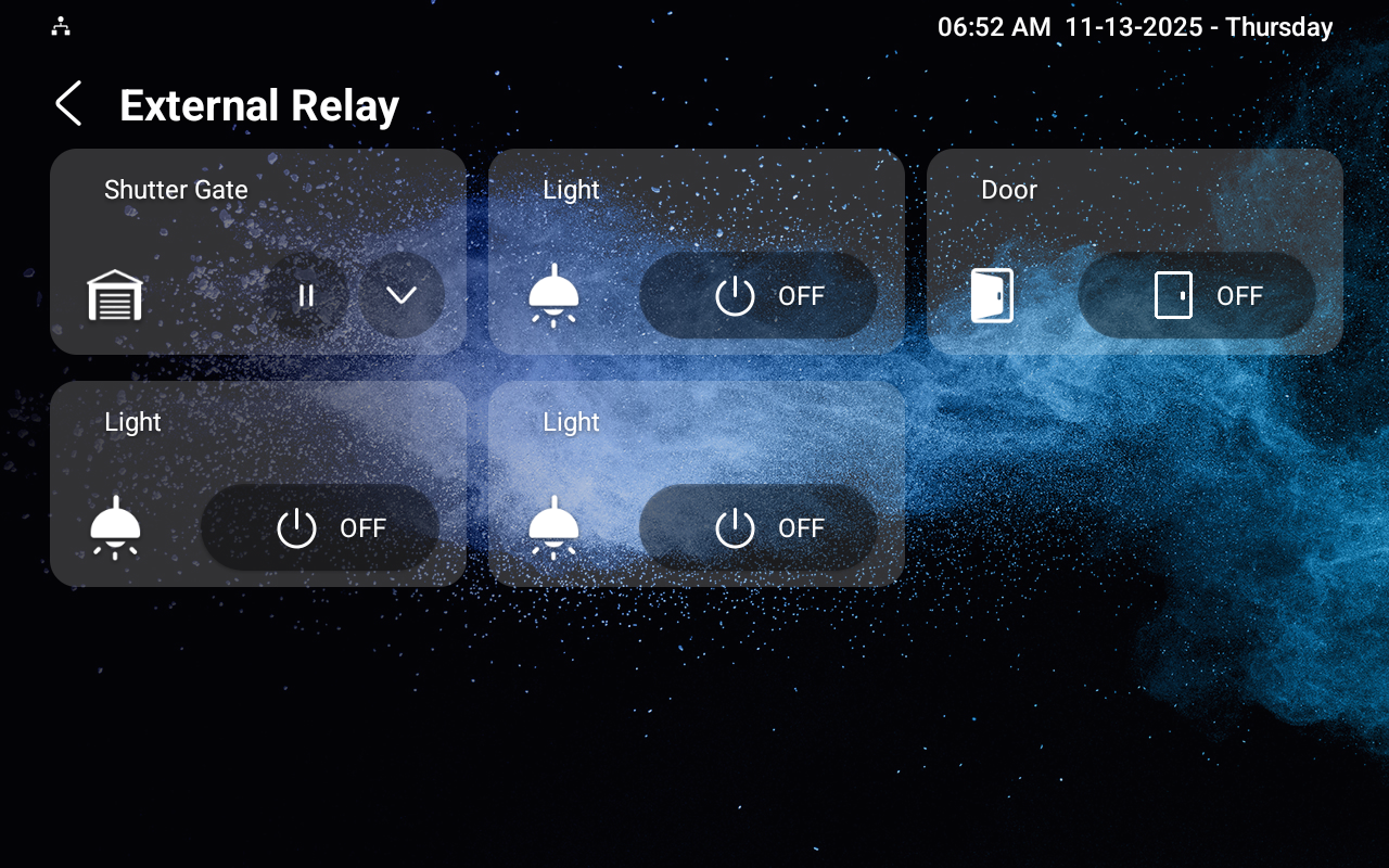
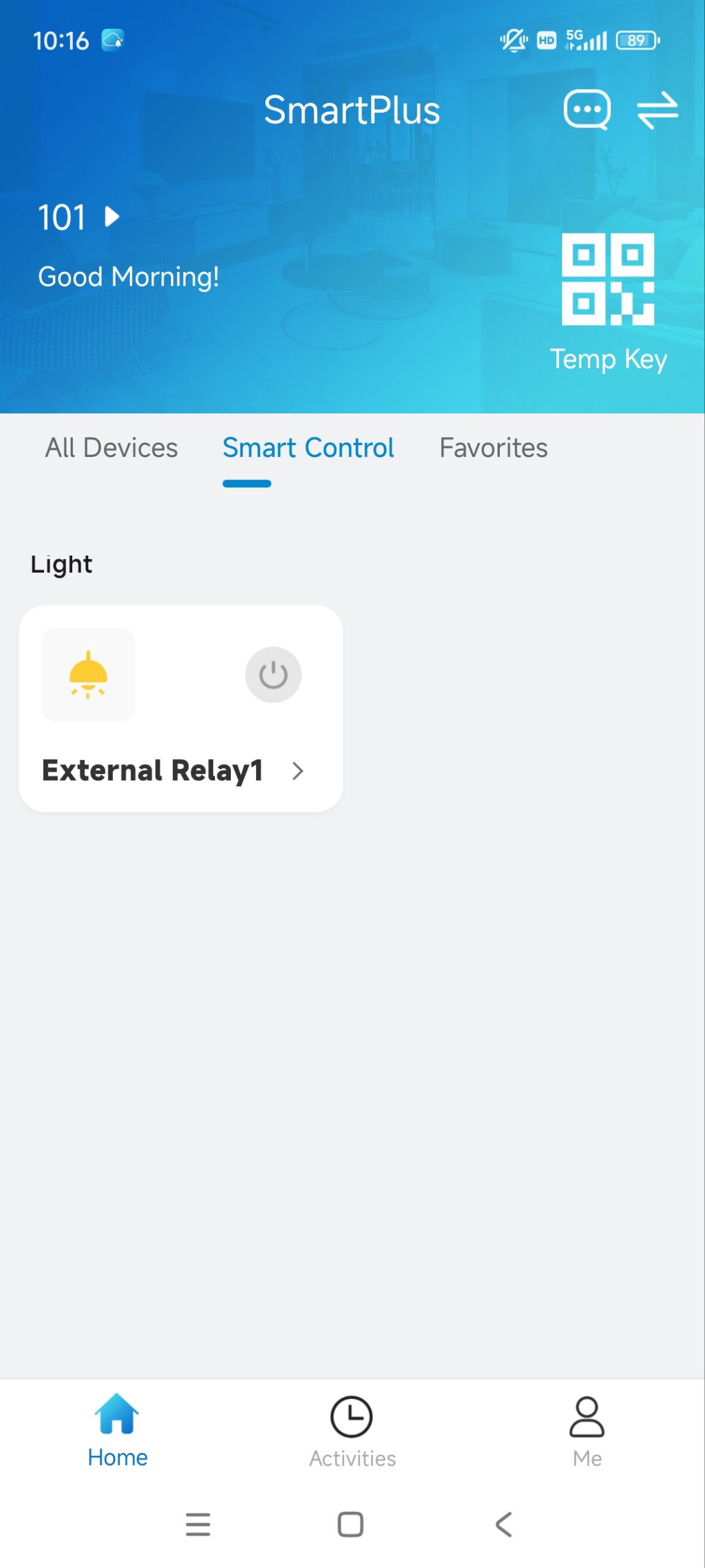
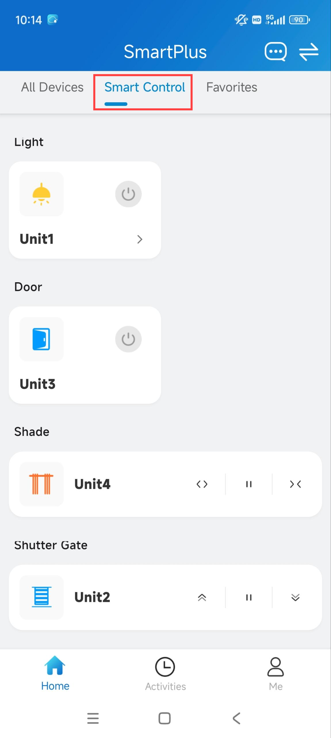
On the SmartPlus App, users can tap specific tabs to turn on lights, open doors, etc, on the Smart Control page.
Display External Relay Buttons
You can display the external relay buttons on the device’s Home or More page for quick access.
Go to the Device > Relay Setting > Home/More Page Display interface.
Select External Relay to be displayed in the desired area. You can rename the button in the Label field.

Click Submit.
RSAC-C1-R8
Changelog
With specific versions or higher, indoor monitors support using RSAC-C1-R8 inputs as configurable security zones with arm/disarm control and alarm triggering.
Supported Model and Minimum Version
S562: 562.30.16.126
Wiring Diagram
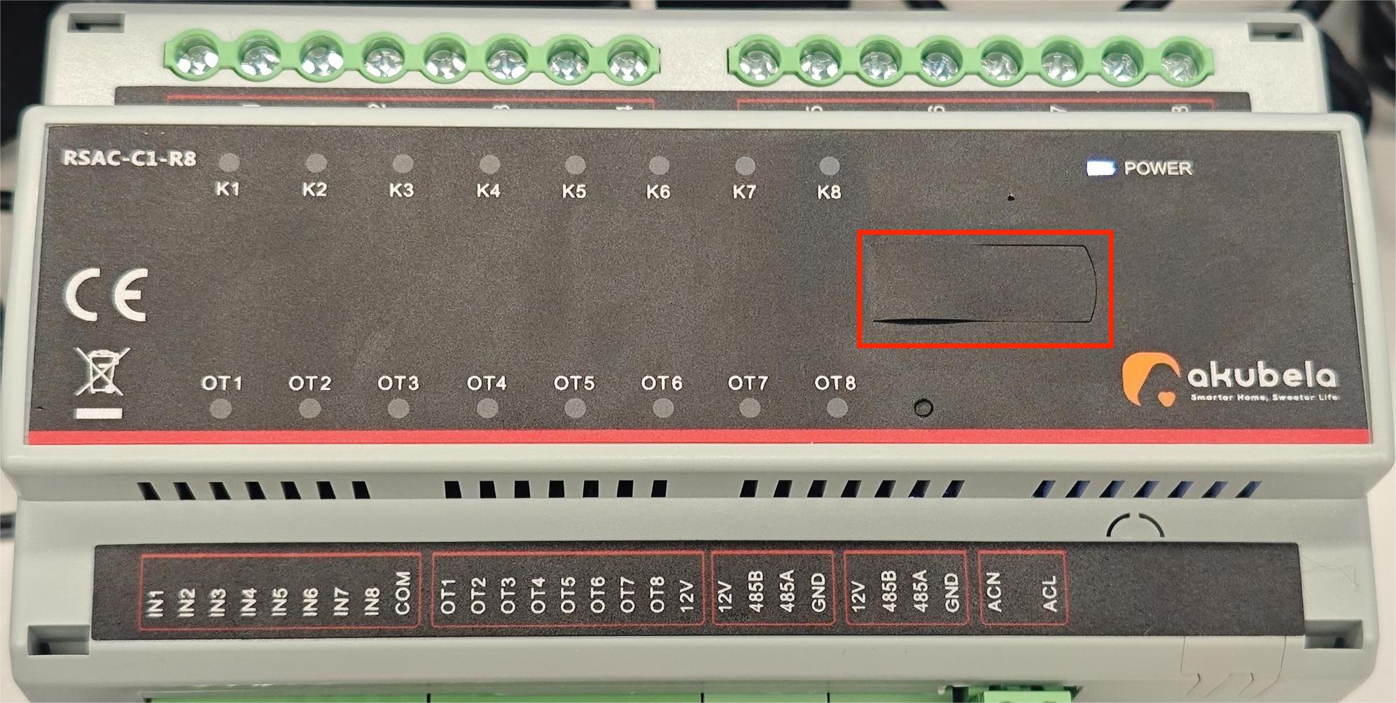
The RSAC-C1-R8 should be connected to Akuvox indoor monitors via RS485 ports. It has 8 relays and 8 outputs that can be connected to smart home devices and controlled by the indoor monitor.
Zone | Port | Wiring Instructions |
|---|---|---|
Relay | K1 ~ K8 | Connect to the load devices. |
L | Connect to a 100- 250VAC line wire. | |
Output | OT1 ~ OT8 | Connect to the negative wire of the output devices. |
12V | Connect to the positive wire of the output devices | |
Input | IN1 ~ IT8 | Connect to one wire of the input devices. NOTE: On the indoor monitor’s web interface, inputs can be linked to outputs/relays. When inputs receive a signal, the corresponding outputs/relays can be triggered. |
COM | Connect to the other wire of the input devices. |
.png)
After wiring, toggle on the DIP switch 1. Otherwise, the indoor monitor will not detect the device.

Configuration on the Web Interface
After correct wiring, you need to configure external relays on the indoor monitor’s web interface.
Use the device IP to log into its web interface with the username and password. The initials are both admin.
Go to the Device > External Relay interface.
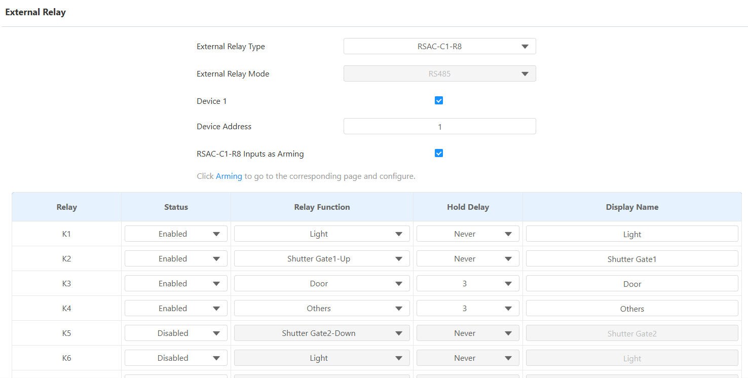
Select RSAC-C1-R8 as the External Relay Type. The indoor monitor can be connected to 3 RCUs. Device 1 is enabled by default. To use more, enable Devices 2 and 3 at the bottom of the web interface.
Enter the device address determined by the DIP switch.
Note
The address mapping is as follows:
Switch Number
Address
1
1
2
2
3
4
4
8
5
16
6
32
Example:
When you toggle on Switch No. 1, enter 1 in the device address box.
When you toggle on Switches No. 1, 2, and 3, add their values (1 + 2 + 4) and enter 7 as the device address.
Enable RSAC-C1-R8 Inputs as Arming if needed. When enabled, the inputs can function as security zones and support arm/disarm operations. Once a connected sensor is triggered while the zone is armed, the system generates an alarm event in the same way as the indoor monitor's built-in security zones.
Enable the desired keys and select the relay function.
Set the Hold Delay time that decides how long the relay is activated. Never means it keeps activated once it is triggered.
Customize the Display Name.
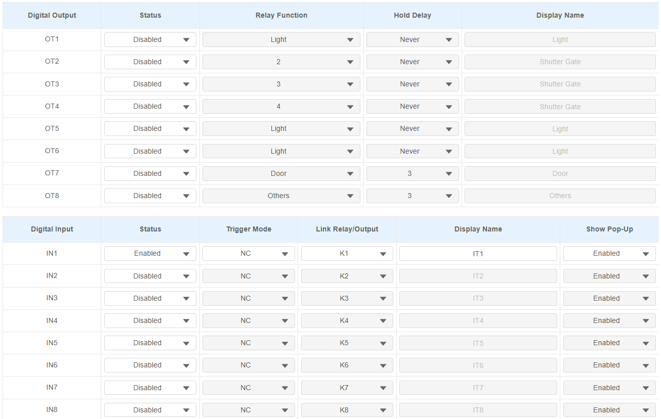
Enable the desired digital outputs and select the function.
Enable the desired digital inputs and select the trigger mode and linked relay/output. When inputs receive a signal, the corresponding outputs/relays can be triggered.
Customize the Display Name.
Enable/disable Show Pop-up. This decides whether to display a prompt on the indoor monitor when the input is triggered.
Click Submit.
Configuration on the SmartPlus Cloud
When the indoor monitor is connected to SmartPlus Cloud, you can configure external relays on the SmartPlus Cloud platform.
Users can control smart home devices on their SmartPlus App easily.
Note
The SmartPlus App version should be 7.14.0003(Android)/7.14.3(iOS) or higher.
ONLY single-family and community projects support this feature.
The following models with specific firmware versions or higher support configuring external relays on the cloud:
S565: 565.30.10.505
S562: 562.30.14.609
Take a community project, for example.
Log in to the SmartPlus Cloud platform with an installer account.
Click
of the target community and go to the apartment where the indoor monitor is installed.Click
of the desired resident and scroll to the Intercom Devices section.
Click
to modify the settings.
Turn on the External Device feature.
Set the Type to RSAC-C1-R8. The indoor monitor can be connected to 3 RCUs. Device 1 is enabled by default. To use more, click Add External Device.
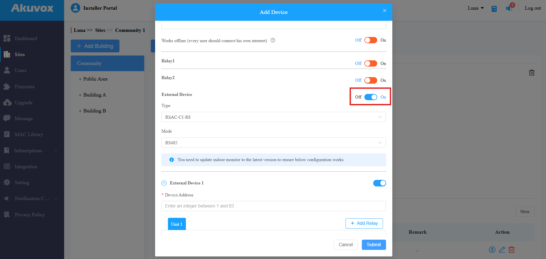
Enter the device address determined by the DIP switch.
Note
The address mapping is as follows:
Switch Number
Address
1
1
2
2
3
4
4
8
5
16
6
32
Example:
When you toggle on Switch No. 1, enter 1 in the device address box.
When you toggle on Switches No. 1, 2, and 3, add their values (1 + 2 + 4) and enter 7 as the device address.
Name the unit and select its function. Further configure the settings. Take Light as an example.
Choose the output interfaces that are connected to the light for controlling its on/off.
Set the Hold Delay time that decides how long the unit is activated. Never means it keeps activated once it is triggered.
If needed, you can add input(s). The input is linked to the relay/output. When inputs receive a signal, the corresponding outputs/relays can be triggered. It can be a button or a sensor connected to the input.
.png)
Click Submit to save the settings.
On the SmartPlus App, users can tap specific tabs to turn on lights, open doors, etc, on the Smart Control page.
Display External Relay Buttons
You can display the external relay buttons on the device’s Home or More page for quick access.
Go to the Device > Relay Setting > Home/More Page Display interface.
Select External Relay to be displayed in the desired area. You can rename the button in the Label field.
Click Submit.
Users can see the external relay button and tap to control devices.