The door phone S532 can be connected to Akuvox answering units through the Akuvox analog switch, achieving easy calling and unlocking.
With the answering units, users can:
answer calls from S532;
open the door for visitors during a call by pressing the button on the unit.
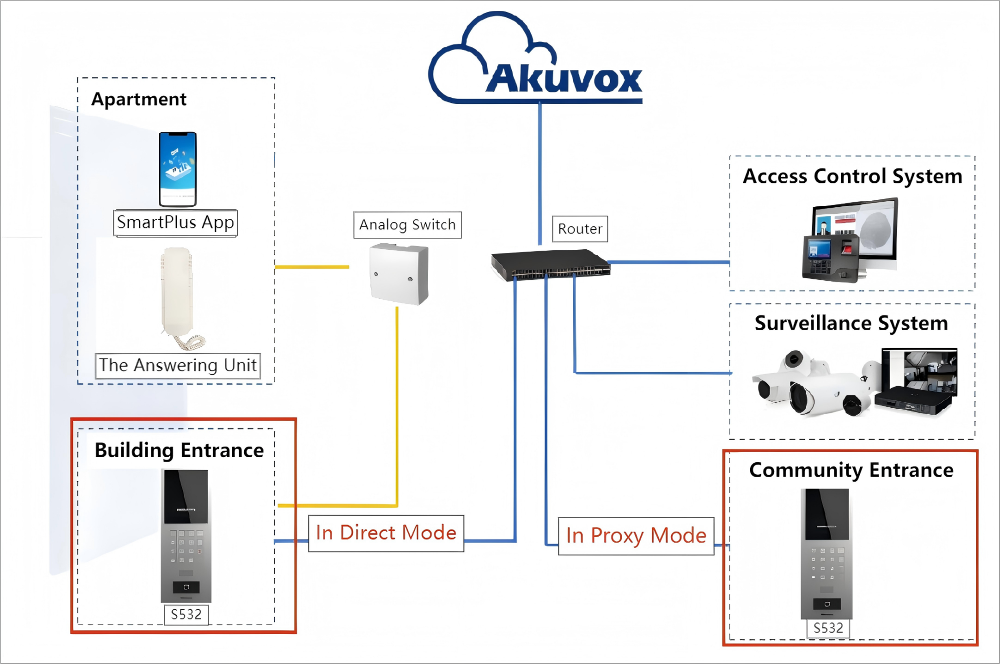
Topology
Direct Mode: The S532 is connected to the analog switch through wires.
Proxy Mode: The S532 is NOT connected to the analog switch, but it can make calls to the answering units through the configuration on its web.
Wirings
Wirings vary by the analog switch used.
Note
The connection between the analog switch and the answering unit. This determines the analog number. This number is the basis for users to call the answering unit on the S532.
Connect Answering Unit to AS11
Connection between S532 and the AS11
Please note that using SEL1 and SEL0 for connection is different. Connecting SEL0 to SEL means the analog number generated by the analog switch is from 0 to 99, while connecting SEL1 to SEL is 100 to 199.

Connection between the AS11 and the Answering Unit
The answering unit has each red(positive) and black(negative) wire.
The red wire is connected to DX, and the black one is connected to EX, generating the analog number XX or 1XX.
For example, in this demonstration diagram, the answering unit is connected to D0 and E2.
Therefore, when S532’s SEL0 is connected to the analog switch’s SEL, the analog number is 02. When S532’s SEL1 is connected to SEL, the analog number is 102.
.png)
Connect Answering Units to AS12
Prefer a visual walkthrough?
Watch: [Video]Akuvox Analog Switch and Answering Unit Wiring Tutorial
One AS12 can be connected to 4 answering units.
The S532 should be connected to a 12V 3A power adapter so that it can power the analog switch and handset.
The blue, black, yellow, and red wire of the analog switch is connected to the S532’s EK, 12V power-in or NC1, GND, and Line ports, respectively. If NC1 is used, S532 will use Relay A for power output; you need to turn on the 12V power output feature on the S532’s web interface and use Relay B for door opening when adding a user.
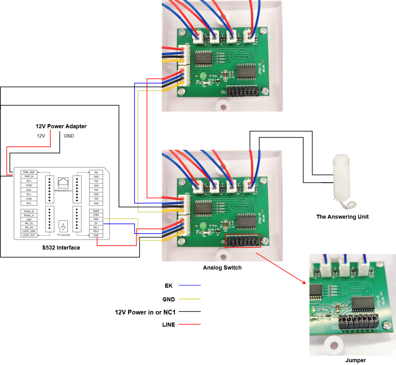
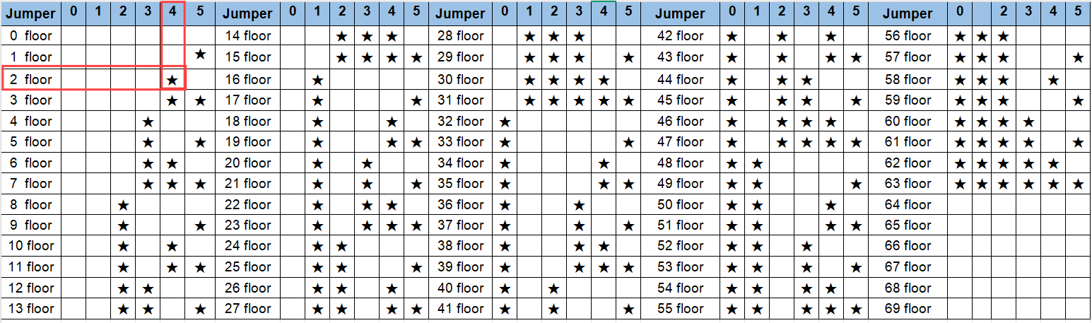
The answering unit is connected to the FX interface. For example, if the unit is installed on the fourth floor and it is connected to F1. The analog number will be 401. F1-F4 corresponds to 01-04.
The jumper 0-5 short circuit defines the floor number. Please refer to the chart below.
★ indicates short circuit. For example, if jumper 4 is short-circuited, the unit is on the second floor. Then, the analog numbers will be 201, 202, 203, and 204.
On-Premise Configuration
After the correct connection, set up the feature on the S532’s web interface. Select the right analog integration brand and assign the analog number to specific users.
Call Setup
Users can enter the analog number or the replaced number on S532(Both in Direct and Proxy modes) to call answering units.
Set the S532 in Direct Mode
Use the device IP to log into its web interface. The default username and password are admin.
Go to Intercom > Basic and select Akuvox as the Adapter brand.

Go to the Directory > User interface and click Add to add a user.
After setting the username and ID, scroll to the Contact Details section and set it as instructed.

Click Submit to save the settings.
Set the S532 in Proxy Mode
Use the device IP to log into its web interface. The default username and password are admin.
Go to Intercom > Basic and select Akuvox as the Adapter brand.

Go to the Directory > User interface and click Add to add a user.
After setting the username and ID, scroll to the Contact Details section and set it as instructed.

Click Submit to save the settings.
Door-opening Setup
Residents can press the button on the answering unit to open doors during a call with the S532 in Direct mode. This does not require extra configuration.
The door opening between S532 in Proxy mode and the answering unit can be achieved by DTMF codes. The S532(Direct) can send DTMF signals to the S532(Proxy).
Go to Intercom > Basic > Analog Setting on the S532(Direct)’s web interface.
Select Akuvox as the Adapter and set the DTMF Send code. If there are multiple doors, just enter the code in series. For example, “0123”.
Go to Access Control > Relay on the S532(Proxy)’s web interface. Set the DTMF code. The code should be consistent with or contained in the DTMF Send code.

Click Submit to save the settings.
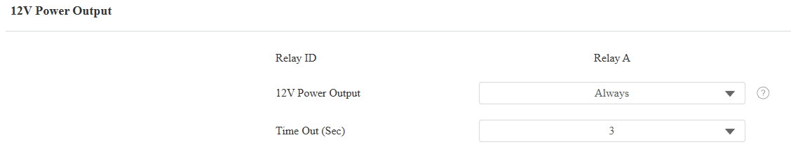
12V Power Output Setup
If you use NC1 to connect the analog switch AS12, you need to set up the 12V power output feature on the web interface.
If not, simply skip this part.
Go to the Access Control > Relay > 12V Power Output interface.
Set 12V Power Output to Always.
SmartPlus Cloud Configuration
When S532s are connected to the SmartPlus Cloud, you can set up the Akuvox analog handsets on the Cloud platform.
Log in to the SmartPlus Cloud platform with an installer account.
Note
S532 with the firmware version 532.30.10.216 or higher support this feature.
Add the S532 to the Public Area
The S532 installed at the community gate should be added to the Public Area of the community.
Navigate to the target community and click Public Area > Intercom Devices.
Click New on the right.
Note
Please click here to view the details of adding a door phone to the public area of a community.
Users can open doors by pressing the button on the analog handset during a call with the S532.
Please note that the DTMF code selected should be the same as that of the analog handset for door opening.
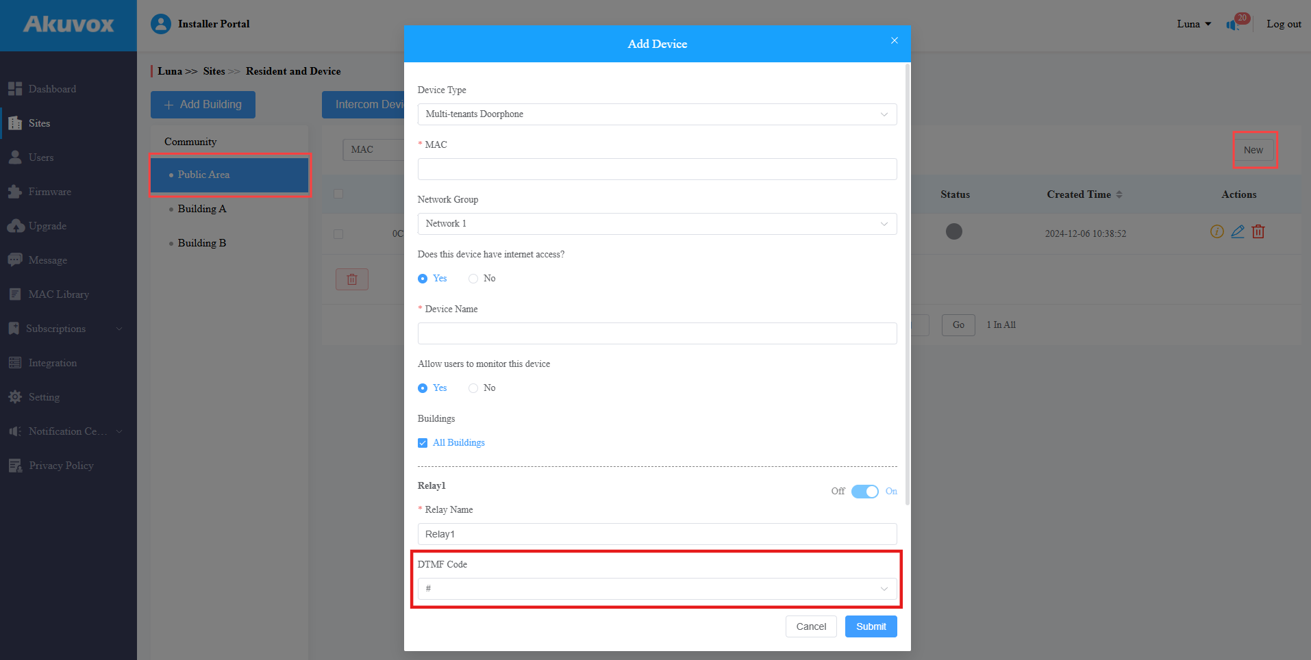
Click Submit.
Add the S532 to the Public Area of Buildings
The S532 installed at the building gate should be added to the public area of the building.
Navigate to the target community and click the Building Name > Intercom Devices.
Click New on the right.
Note
Please click here to view the details of adding a door phone to the public area of a building.
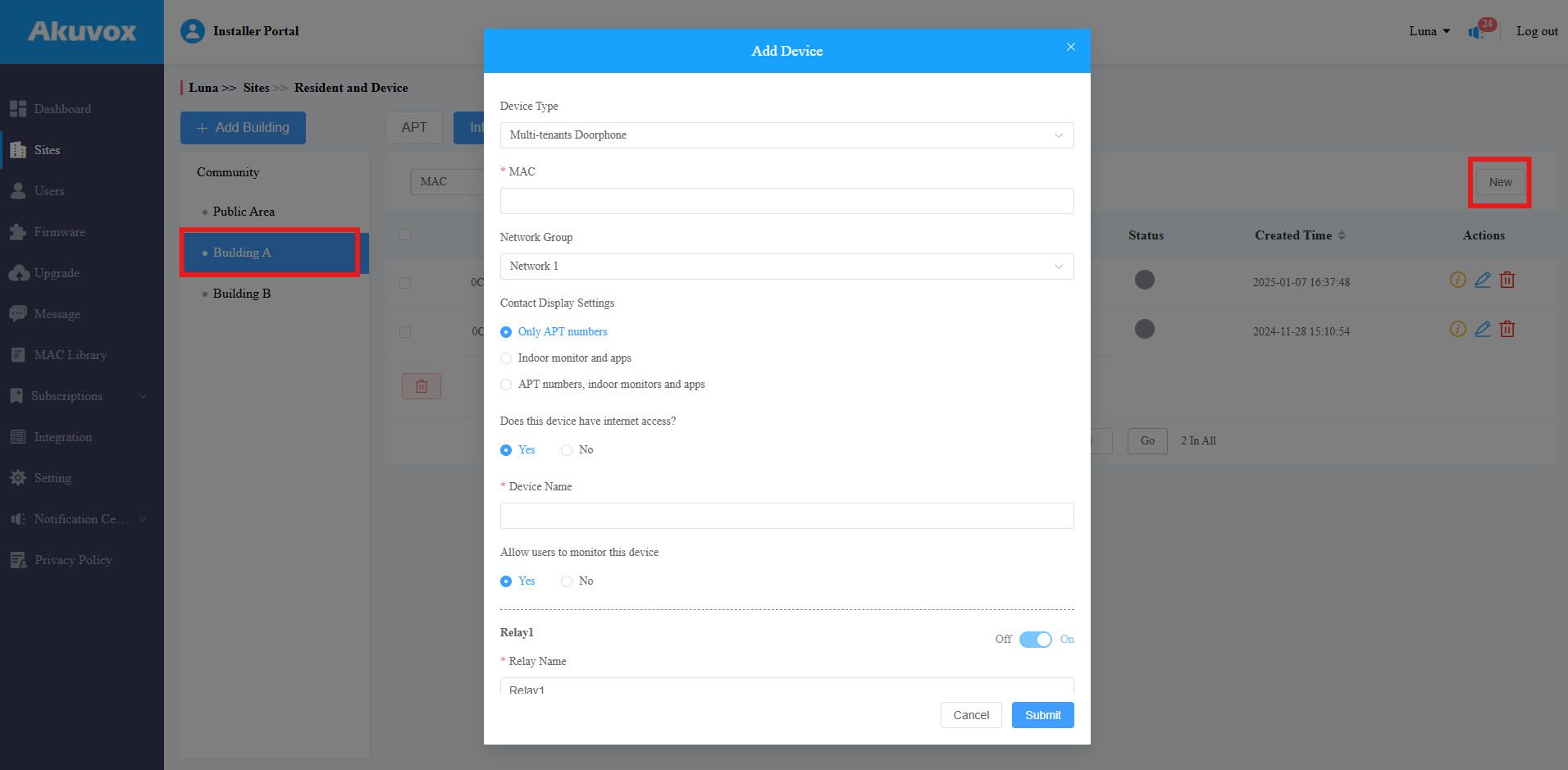
Click Submit.
Add the Analog Handset
Navigate to the target Community > Building.
Click
 of the target apartment.
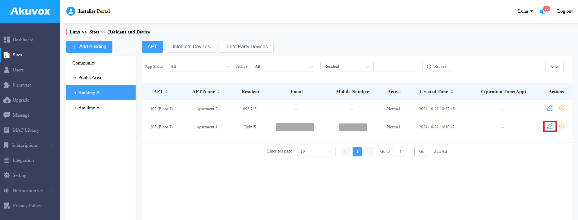
Find the Analog Handset part. Click New on the right.
Enter the analog handset name, number, and DTMF code. The DTMF code should be the same as the S532s’.
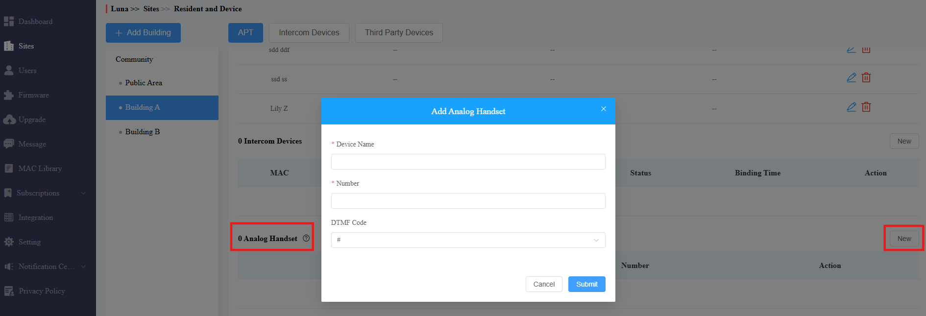
Click Submit.
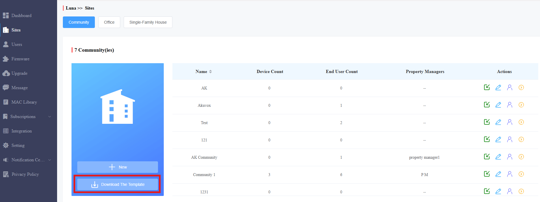
You can also batch import the analog handsets with residents and devices using a template.
Click Download the Template on the Sites module.
Fill in the template as instructed. View instructions by hovering your mouse cursor over specific columns.

Click
 to import the file.