User-specific Access Methods
The Bkey, and license plate settings should be assigned to a particular user for door opening.
When adding a user, you can also customize settings such as defining the door access schedule to determine when the code is valid and specifying which relay to open.
To add a user, go to Directory > User interface and click +Add.
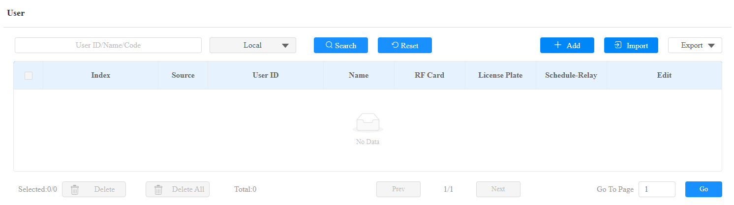

User ID: The unique identification number assigned to the user.
Name: The name of this user.
Unlock by Bkey
On the Directory > User > +Add interface, find the BLE Code&Bkey section.

Code: The Bkey code that the device reads.
Note
Click here to view the detailed steps of configuring Bkey.
Each user can have a maximum of 5 Bkeys added.
The device allows adding 20,000 users.
Unlock by License Plate
Akuvox offers two main ways to identify vehicles and open gates.
Use a third-party LPR(License Plate Recognition) camera to recognize the license plate of the vehicle.
Use the Akuvox long-range card reader ACR-CPR12 to recognize the UHF card attached to the vehicle's windshield.
To assign the license plate to a user, find the License Plate part on the Directory > User > +Add interface.

Add: A user can have up to 5 license plates.
Duration: Enable/disable Long-term Vehicle. It is enabled by default. If disabled, specify when the vehicle can enter or exit the parking lot.
Unlock by Authorized Phone Number
The Web Relay supports Dial-to-Open. Authorized phone numbers can be configured to trigger relay actions when calling the device. This feature is only available for WR01-L.
Add the phone number on the Directory > User > +Add interface, and find the Authorized Phone Number section.

Number: A whitelisted phone number used for authentication. The input consists of a country code selector and a phone number field.
The phone number supports up to 15 digits.
Each user can have a maximum of 5 numbers added.
Important Note
If the destination number is in the same country as the Web Relay’s SIM card, leave the country code blank to avoid call failures.
Access Setting
You can customize access settings, such as defining the door access schedule to determine when the code is valid and specifying which relay to open.
On the Directory > User > +Add interface, scroll to the Access Setting section.
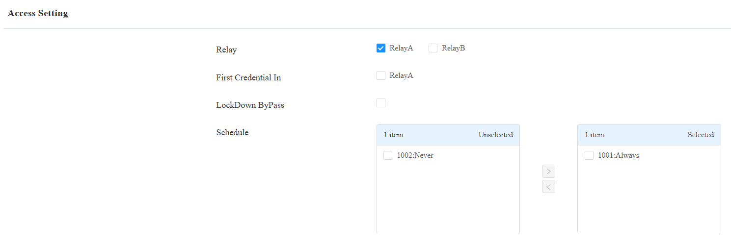
Relay: Specify the relay that can be unlocked by the user’s credentials.
First Credential In: This decides whether the user can keep the door open during the scheduled time after activating it.
Lockdown Bypass: This decides whether the user can open the door when the door is locked during the scheduled time.
Schedule: Grant the user access to open designated doors during preset periods by relocating the desired schedule(s) from the left box to the right one. Besides custom schedules, there are 2 default options:
Always: Allows door opening without limitations on door open counts during the valid period.
Never: Prohibits door opening.
Unlock by Bluetooth
The Bluetooth-enabled SmartPlus App enables users to enter the door without tapping on the device. They can open the door with the app in their pockets or wave their phones toward the device as they get closer to the door.
This feature requires the device to be connected to the SmartPlus Cloud.
Set it up on the web Access Control > BLE interface.
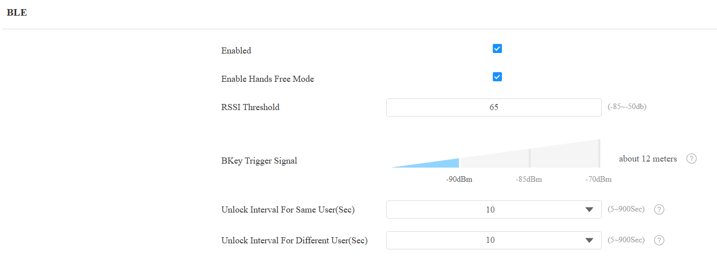
RSSI Threshold: Set the received signal strength. Higher values indicate stronger signal strength, making it easier to receive the Bluetooth signal.
Bkey Trigger Signal: There are three ranges that determine the Bkey trigger distance, ranging from 1m to 12m.
Unlock Interval For Same User(Sec): Set the time interval between consecutive Bluetooth door access attempts for the same user.
Unlock Interval For Different Users(Sec): Set the time interval between consecutive Bluetooth door access attempts for different users.
Note
To learn about detailed configuration steps for different Bluetooth-based access methods, you can click the following articles.
Unlock by HTTP Command
You can unlock the door remotely without approaching the device physically for door entry by typing in the created HTTP command (URL) on the web browser to trigger the relay when you are not available by the door for door entry.
Set it up on the Access Control > Relay > Open Relay via HTTP interface.
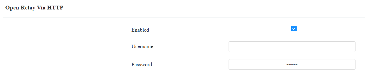
Username: Set a username for authentication in HTTP command URLs.
Password: Set a password for authentication in HTTP command URLs.
Tip
Here is an HTTP command URL example:

Note
Click here to view how to set up door opening by HTTP commands.
Unlock by Exit Button
When users need to open the door from inside by pressing the Exit button, you need to set up the Input terminal that matches the Exit button to activate the relay for the door access.
Click here to watch the instruction video.
Set it up on the web Access Control > Input interface.
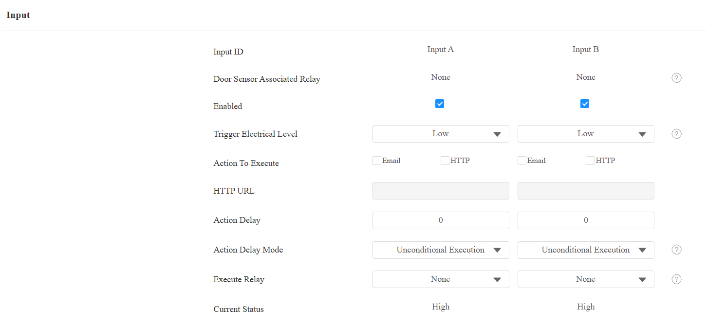
Door Sensor Associated Relay: This indicates the Relay bound to the Input when the Input is configured as a Door Sensor. Displays None when the Input is not associated with any Relay.
Enabled: To use a specific input interface.
Trigger Electrical Level: Set the input interface to trigger at a low or high electrical level.
Action To Execute: Set the desired actions that occur when the specific Input interface is triggered.
Email: Send a screenshot to the preconfigured Email address.
HTTP: When triggered, the HTTP message can be captured and displayed in the corresponding packets. To utilize this feature, enable the HTTP server and enter the message content in the designated box below.
HTTP URL: Enter the HTTP message if selecting HTTP as the action to execute. The format is http://HTTP server’s IP/Message content.
Action Delay: Specify how many seconds to delay executing the preconfigured actions.
Action Delay Mode:
Unconditional Execution: The action will be carried out when the input is triggered.
Execute If Input Still Triggered: The action will be carried out when the input stays triggered. For example, if the door stays open after triggering the input, an action such as an email will be sent to notify the receiver.
Execute Relay: Specify the relay to be triggered by the actions.
Current Status: Display the status of the input signal.