5.5.1 Function List Setting
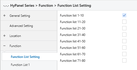
Figure 5.5.1: Function List Setting interface
Function list x-x(x=1..80)
Enables the specified range of function pages. Function pages are grouped in sets of 10.
For example, if Function List 1-10 is enabled, pages Function List 1 to 10 become visible for configuration. Up to 80 pages are supported in total.
Note:
Pages 1-40: Supports Basic function devices only.
Up to 8 devices per page.
Pages 41-80: Supports both Basic and Advanced function devices.
Either 8 Basic devices per page OR 1 Advanced device per page.
System Totals: The total system capacity scales based on your configuration.
Maximum Capacity: Up to 640 devices (when utilizing all pages for Basic devices).
Minimum Capacity: Approximately 320 devices (when utilizing Advanced devices on pages 41–80).
5.5.2 Function List x--Basic Function
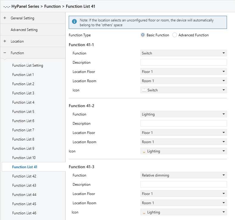
Figure 5.5.2: Function List x setting interface
Function Type
Defines the type of function page.
Options:
Basic Function: Allows configuration of up to 8 devices per page.
Advanced Function: Allows only 1 device per page.
Function
Defines the device type.
When “Basic Function” is selected, available options include:
Disable
Switch
Lighting
Relative Dimming
Brightness dimming
Relative + Brightness dimming
Brightness + Colour temperature
Shade position
Roller blind position
Venetian blind position and slat
Venetian Curtain position and slat
Shade step/move
Roller blind step/move
Value sender
Scene control
External Device(From bus)
External Device(Non-KNX)
When “Advanced Function” is selected, available options include:
Disable
HVAC
Air conditioner
Audio control
Color control type
Air quality display
Floor heating
Ventilation system
Energy metering display
Advanced switch
Note:
The actual parameters displayed will vary based on the selected function type. Pages 1-40 are limited to Basic Functions; Pages 41-80 support all function types.
Detailed parameter settings for each function type are covered in the following sections. This section focuses on Basic Functions.
Description
Sets the name of the floor. Supports up to 31 characters, with a display limit of 10 Chinese characters.
Location Floor
Sets the floor where the device is located.
Options: Floor 1-10
Note:
If the selected floor is not enabled in the Location section, the device will be placed under the “Others” room by default.
Location Room
Assign the device to a room under the selected floor.
Options:
None: The device will be placed under the selected “Location Floor”.
Room1-10
Note:
If the selected room is not checked in “Floor x”, the device will also default to the “Others” room.
Icon
Select a device icon when using Basic Functions. Icon options vary by function type.
Example(Switch type):
Switch
Lighting
Socket
Note:
Icon selection is unavailable for External Device (From Bus) and External Device (Non-KNX) when Object Type is set to 14-byte.
Basic Function
When Basic Device is selected, the available options are as follows:
Switch: Used for switch control
The objects "Switch" and "Switch Status" are visible.
To clarify, "Switch" refers to the operation object of the switch actuator, and "Switch Status" corresponds to its status object. When the "Switch Status" receives a status response from the actuator, the icon on the panel updates accordingly.
Lighting: Used for lighting control
The objects "Switch" and "Switch status" are visible.
"Switch" refers to the lighting actuator's switch object, while "Switch status" reflects the lighting status. When the actuator returns a status response, the panel icon updates in real time.
Note:
When this type is selected, the lighting devices will be categorized under Lights in the HyPanel, allowing for controlling lights with only an on/off function.
Relative dimming: Allows both switching and relative dimming.
The following objects are visible: "Switch", "Switch status", "Relative dimming", and "Brightness status".
Short press on the switch button sends a switch command.
Short press on the "+" or "−" button sends a step dimming command (default step: 12.5%, not adjustable).
Long press on the "+" or "−" button triggers a relative dimming command; release to stop. Only start-stop dimming mode is supported.
Note:
The brightness bar only displays the current brightness; it does not support touch dimming.
Brightness dimming: Enables switch and brightness control.
The visible objects are: "Switch", "Switch status", "Brightness dimming", and "Brightness status".
Short press on the switch button sends a switch command.
Slide on the brightness bar for direct dimming.
"Brightness dimming" and "Brightness status" typically work together, corresponding to the actuator’s brightness control and status feedback respectively.
Relative + Brightness dimming: Combines relative and absolute dimming.
The visible objects are: "Switch", "Switch status", "Brightness dimming", "Brightness status", and "Relative dimming".
Short press on the switch button sends a switch command.
Short press "+" or "−" for step dimming (default step: 12.5%, not adjustable).
Long press "+" or "−" for relative dimming; release to stop.
Slide the brightness bar for direct brightness adjustment.
Brightness + Colour Temperature: Controls both brightness and color temperature.
Visible objects include “Switch” and “Switch Status”, supporting switch control and status feedback.
Colour temperature control types include Brightness+Colour Temp value, Brightness+Colour Temp percentage, or direct control.
Objects support color temperature, brightness control, and status feedback.
The color temperature range is 2000-7000K with adjustable high/low thresholds.
Note:
If the minimum value is greater than or equal to the maximum, the range defaults to 2000-7000K.
Shade position: For curtain control.
Curtain position can be adjusted using a percentage slider or three control buttons: Open, Close, Stop.
Roller blind position: For roller or lift blinds
Blind position can be adjusted using a percentage slider or three control buttons: Up, Down, and Stop.
Venetian blind position and slat: For venetian blinds
Both the blind position and slat angle can be adjusted using a percentages slider or three buttons: Up, Down, and Stop.
Venetian curtain position and slat: For sheer curtains
Both the curtain position and slat angle can be adjusted using a percentages slider or three buttons: Up, Down, and Stop.
Shade step/move: For step-based curtains
Support controlling via three buttons: Open, Close, and Stop.
Support step adjustment via “+” and “-” buttons.
Roller blind step/move: For step-based roller blinds
Support controlling via three buttons: Up, Down, and Stop.
Support step adjustment via “+” and “-” buttons.
Value send
Sends specified values in different data types.
Scene control
Touch to call a scene; press to save a scene.
External Device(From bus): Sync sensors on bus
Syncs sensor statuses from the bus to the HyPanel.
External Device(Non-KNX): Sync non-KNX sensors
Sends sensor status from HyPanel to the KNX bus.
The following parameters are visible when the “Brightness+Colour Temperature” is selected.
- Reaction on ”off " operation
Determines the behavior when the device is turned off.
Options:
Only switch object send value 0
Brightness objects send value 0
- Colour Temperature Control type
Sets the methods of color temperature control.
Options:
Brightness+2byte absolute value: Sends 1-byte brightness and 2-byte colour temperature values.
Brightness+1byte relative percentage value: Sends 1-byte brightness and 1-byte percentage-based colour temperature.
Directly(with warm/cool white algorithm): Uses a built-in algorithm to convert brightness and colour temperature values into warm/cool white levels. Two 1-byte objects are used to control brightness for warm and cool white LEDs.
- Status feedback object
This parameter sets the type of feedback object. It is visible only when “Directly (with warm/cool white algorithm)” is selected.
Options:
Brightness+Colour Temperature: Ensures compatibility with panels using brightness and colour temperature feedback.
Warm/cool white brightness: Ensures compatibility with actuators using separate warm and cool white brightness feedback.
- Min. colour temperature [2000..7000]K
- Max. colour temperature [2000..7000]K
These two parameters set the upper and lower limits for color temperature.
Options: 2000..7000
Note:
When the minimum value is greater than or equal to the maximum value, the range defaults to 2000K~7000K。
The following parameters are visible when “Shade step/move” option is selected.
- Step value
Sets the step value for adjusting the curtain position.
Options:
100%
50%
25%
12.5%
6.25%
3.13%
1.56%
The following parameters are visible when “Roller blind step/move” option is selected.
- Step value
Sets the step value for adjusting the roller blind position.
Options:
100%
50%
25%
12.5%
6.25%
3.13%
1.56%
The following parameters are visible when “Value send” option is available.
- Datatype of object during a short/long press
Sets the data type of values to be sent for short press or long press.
Options:
1bit value[On/Off]
2bit value[0..3]
4bit value[0..15]
1byte signed value[-128...127]
1byte unsigned value[0..255]
1byte percentage [0..100]
2byte signed value[-32768...32767]
2byte unsigned value[0..65535]
2byte float value
4byte signed value
4byte unsigned value
4byte float value
- Reaction to short/long press
Defines the behavior when pressing the button briefly or for a long duration.
When the “Datatype of object during a short/long press” is set to “1bit value [On/Off]”, options are:
none: Do not send a value.
off: Send an "off" value.
on: Send an "on" value.
toggle: Cycle between "on" and "off" values.
For other value type in “Datatype of object during a short/long press” , options are:
none
send value 1
send value 2
send value 1 <->send value 2: Cycle between "value 1" and "values 2”
- Value1, Value2
Visible only when a data type other than 1-bit is selected. It sets the value to be sent during operation. The valid value range depends on the selected object type.
The following parameters are visible when “Scene control” option is selected.
- Output scene No.
Defines the scene number to be sent when the scene is triggered.
Options: 1-64
The following parameters are visible when “External Device(From bus)” option is available.
- Object type
Specifies the type of the sensor.
Options:
1bit
1byte
2byte
4byte
14byte
- Parameter “External Device”
Defines the type of sensor based on the required sensor function:
When the previous "Object type" is set to "1bit," the available options are:
Door&Window Sensor
Smoke Sensor
CO Sensor
Gas Sensor
Motion Sensor
Flood Sensor
SOS Emergency Button
Occupancy Sensor
Custom
When the previous "Object type" is set to "1byte," the available options are:
Percentage
Signed
Unsigned
Error code
Custom
When the previous "Object type" is set to "2byte," the available options are:
Temperature
Humidity
CO2
VOC
PM2.5
PM10
Brightness
Windspeed
Error Code
Voltage(V)
Voltage(mV)
Current(A)
Current(mA)
Power(W)
Power(KW)
Custom
When the previous "Object type" is set to "4byte," the available options are:
Power(W)
Power(KW)
Custom
When the previous "Object type" is set to "14byte", the available options are:
Error Text
Custom
- Device Type
Visible when "Custom" is selected for the previous parameter.
It is used to customize the sensor type. Maximum input is 13 characters, displaying up to 4 Chinese characters. HyPanel will generate the corresponding sensor type based on the input value.
The following parameters are visible when “External Device(Non-KNX)” option is selected.
- Object type
Specifies the type of non-KNX external sensor.
Options:
1bit
1byte
2byte
4byte
14byte
- External Device
Defines the type of sensor based on the required sensor function.
When "Object type" is set to "1bit," the available options are:
Door&Window Sensor
Smoke Sensor
CO Sensor
Gas Sensor
Motion Sensor
Flood Sensor
SOS Emergency Button
Occupancy Sensor
Custom
When "Object type" is set to "1byte," the available options are:
Percentage
Signed
Unsigned
Error code
Custom
When "Object type" is set to "2byte," the available options are:
Temperature
Humidity
CO2
VOC
PM2.5
PM10
Brightness
Windspeed
Error Code
Voltage(V)
Voltage(mV)
Current(A)
Current(mA)
Power(W)
Power(KW)
Custom
When "Object type" is set to "4byte," the available options are:
Power(W)
Power(KW)
Custom
When "Object type" is set to "14byte," the available options are:
Error Text
Custom
5.5.3 Function x--HVAC
The parameter settings interface Function x - HVAC, as shown in Figure 5.5.3, primarily configures parameters for fan control and some basic controls for HVAC.
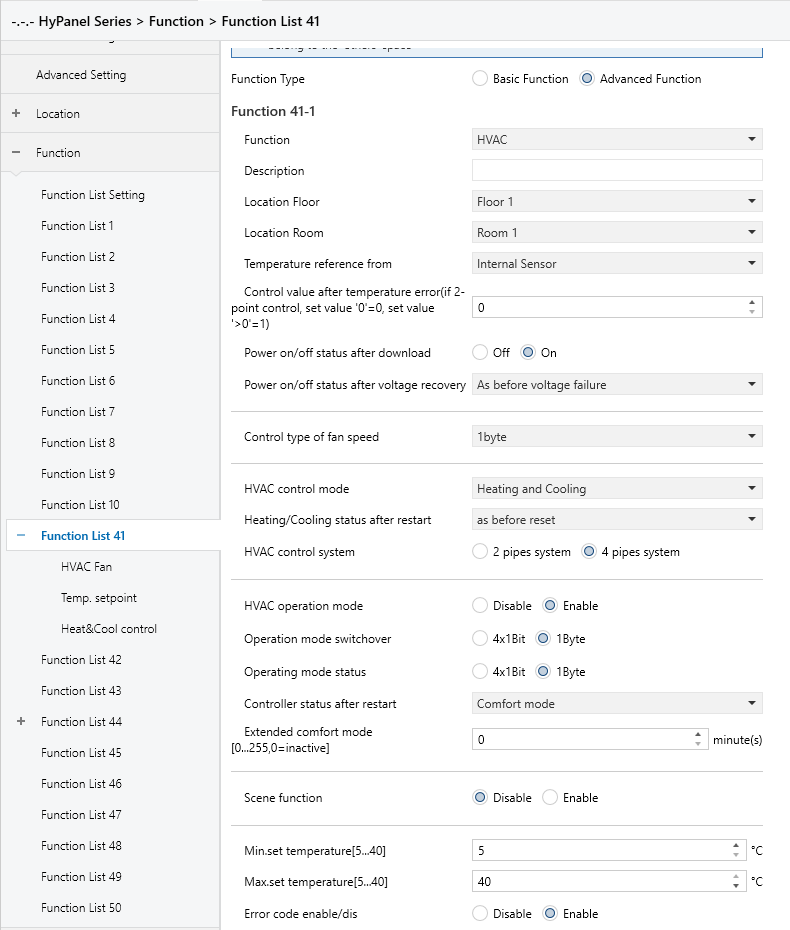
Figure 5.5.3: Function x-- HVAC interface
Temperature reference from
Sets the source of temperature reference for HVAC.
Options:
Internal sensor
External sensor
Internal sensor combine with External sensor
When selecting internal sensor, the temperature is determined by the internal sensor settings in the parameter interface “General sensor”.
The following two parameters are visible when an external temperature sensor option is selected.
- Time period for request external sensor [0 .. 255]min
Defines the interval at which the device sends read requests to the external temperature sensor.
Options: 0 ... 255
- Read external sensor after restart
Specifies whether the device should immediately request data from the external sensor after a restart.
Options:
No: The device waits for the next preset interval following a bus voltage recovery or program download.
Yes: The device immediately sends a read request after bus voltage recovery or program download.
This parameter is visible when HVAC temperature reference is “Internal and external sensors combination”.
- Combination ratio
Sets the proportion of temperature measurement between the internal and external sensors.
Options:
10% Internal to 90% External
20% Internal to 80% External
…
80% Internal to 20% External
90% Internal to 10% External
For example, if the ratio is set to “40% Internal to 60% External”, the calculated control temperature is: (Internal sensor × 40%) + (External sensor × 60%). This computed temperature is used for HVAC control and display.
If either sensor fails, the system will fall back to the functional sensor.The HVAC function of the device will manage and display the resulting temperature.
Control value after temp.error[0..100%](If 2-point control,set value ’0 ’=0,set value ’>0 ’=1)
Sets the control value used when a temperature error occurs.
Options: 0..100
In 2-point control mode:
Value = 0 → Control output = 0
Value > 0 → Control output = 1
Power on/off status after download
Defines the HVAC interface status after application download.
Options:
Off
On
Power on/off status after bus recovery
Defines the HVAC interface status after bus power is restored.
Options:
On: When power is restored, the device will be in the On state, and the interface will be operational. THVAC system resumes operation based on control mode.
Off: When power is restored, the device will be in the Off state, and the interface will not be operational. HVAC remains off with no control or computation.
As before voltage failure: Returns to the last status before power loss.
Control type of fan speed
Sets the data type of fan speed.
Options:
Disable: Not allowed to control fan speed.
1bit: The object type of fan speed control is 1bit.
1byte: When the object type of fan speed control is 1byte, the HVAC_Fan parameter interface becomes visible. Click on HVAC_Fan_1byte to view details.
Fan speed auto
When the “Control type of fan speed” parameter is set to “1bit” or “1byte”, this parameter becomes visible, allowing you to enable automatic control of fan speed.
Options:
Disable
Enable: Enables automatic fan speed control.
HVAC control mode
Sets the output control mode of the HVAC system.
Options:
Heating
Cooling
Heating and Cooling. When selected, the following two parameters are visible.
- Heating/Cooling status after restart
Sets the heating/cooling output control mode after the device restarts.
Options:
Heating
Cooling
As before reset: After a bus power reset, the device restores its previous control mode. After an re-download, the mode is undefined and must be manually set.
- HVAC control system
Specifies the HVAC system type based on water piping.
Options:
2 pipes system: A single valve controls both heating and cooling via one supply/return line.
4 pipes system: Two valves control separate hot and chilled water lines for heating and cooling respectively.
HVAC operation mode
Sets whether to enable the operation mode of the HVAC system.
Options:
Disable
Enable: When selected, the following four parameters become visible:
- Operating mode switchover
Sets the object type for switching operating modes.
Options:
4x1bit: When selected, four 1bit objects are visible:
HVAC Input -- Comfort mode
HVAC Input -- Economy mode
HVAC Input -- Frost/Heat protection mode,
HVAC Input -- Standby mode
Activating a mode triggers the corresponding object to send a telegram “1”; otherwise, it transmits “0”.
1byte: When selected, the object “HVAC Output -- HVAC mode” is visible. The telegram values sent and their meanings are as following:
1: Comfort mode
2: Standby mode
3: Economy mode
4: Frost/Heat protection mode
- Operating mode status
Sets the object type for mode status feedback.
Options:
4x1bit: The device switches among different modes based on the ON or OFF telegrams received by the following four 1-bit objects:
HVAC Input-- Comfort mode
HVAC Input-- Economy mode
HVAC Input-- Frost/Heat protection mode
HVAC Input-- Standby mode
If the first three are all "0", Standby mode is activated.
1byte: Mode changes based on received values:
1: Comfort mode
2: Standby mode
3: Economy mode
4: Frost/Heat protection mode
- Controller status after restart
Defines the operating mode after a device restart.
Options:
Standby mode
Comfort mode
Economy mode
Frost/heat protection
- Extended comfort mode[0.. 255,0=inactive]min
Sets the delay time for automatically switching from Comfort to Economy mode.
Options: 0 ~ 255
Value = 0: No automatic switch
Value = 1-255: Delay in minutes before switching
Note:
This setting only applies to transitions Economy mode and Comfort mode.
The following setting parameters are visible when the operating mode of the HVAC system is disabled.
- Basic setpoint temperature [℃]
Defines the default temperature setpoint.
Options:
10
10.5
...
35
Scene function
Sets whether to enable the scene function.
Options:
Disable
Enable: Enables scene subpage.
Min. /Max. set temperature [5..40]℃
Defines the allowable temperature setting range.
The minimum value must be less than the maximum value; otherwise, default settings will be restored.
If the set temperature exceeds limits, it will be adjusted automatically to remain within the defined range.
Error code enable/dis
Sets whether to enable the error code function.
Options:
Disable
Enable: This will generate three group objects: "Failure status," "Error code," and "Error text," for displaying different types of error codes.
5.5.3.1 HVAC Fan
This interface is visible when the “Control type of fan speed” parameter is set to 1byte, as shown in Figure 5.5.3.1.
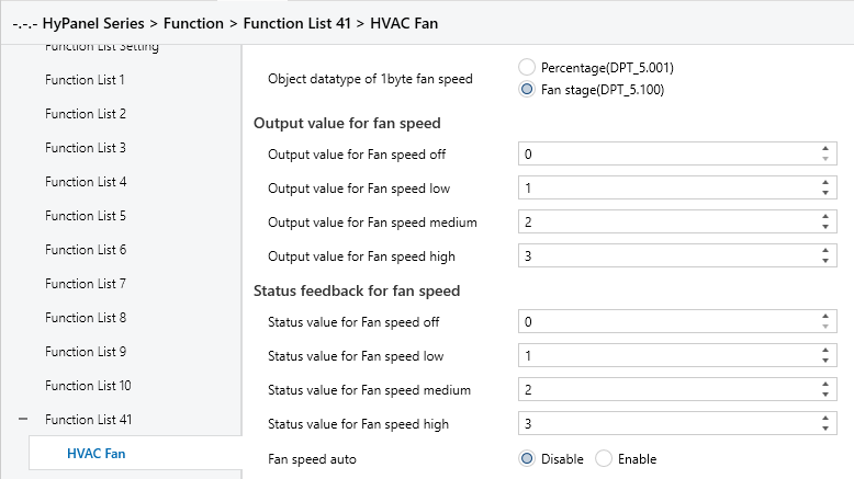
Figure 5.5.3.1: HVAC Fan_1byte interface
Object datatype of 1byte fan speed
Sets the data type of 1byte fan speed.
Options:
Percentage (DPT 5.001)
Fan stage (DPT 5.100)
Output value for Fan speed
Output value for Fan speed off/low/medium/high
These parameters define the output values for switching to Off, Low, Medium, and High fan speeds.
Available value ranges depend on the data type set above: 0...255 or 0...100.
Status feedback for Fan speed
Status value for Fan speed off/low/medium/high
Defines the status feedback values for each fan speed level. The device updates the displayed fan speed based on the received feedback.
Options: 0...255 or 0...100, depending on the object type.
Fan speed auto
Enables automatic fan speed control. When enabled, the corresponding object will be displayed.
5.5.3.2 Temp.setpoint
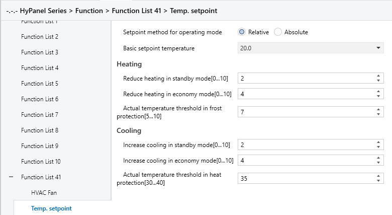
Figure 5.5.3.2 (1): Temp.setpoint_Relative interface
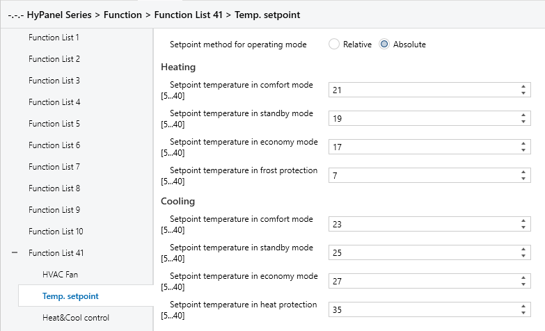
Figure 5.5.3.2 (2): Temp.setpoint_Absolute interface
The interface is visible when the HVAC operation mode is enabled, displayed based on the control mode.
Setpoint method for operating mode
Sets the actual adjusting method for panel temperature setpoints.
Options:
Relative: The setpoints for Economy and Standby modes are calculated based on a defined base temperature.
Absolute: Each mode has an independent setpoint temperature.
The following parameters are visible when the temperature setpoint adjusting method is set to “Relative”.
Basic setpoint temperature [℃]
Sets the base temperature used to derive the Comfort mode setpoint.
Options:
10
10.5
...
35
This value can be modified via the “Setpoint adjustment” object. Changes are saved even after a bus power-down.
Reduced heating in standby mode [0..10]℃
Increased cooling in standby mode [0..10]℃
Sets the temperature setpoint for Standby mode.
Options: 0 ~ 10 [℃]
Heating: Setpoint = Base value - this offset
Cooling: Setpoint = Base value + this offset
Reduced heating during economy mode [0..10]℃
Increased cooling during economy mode [0..10]℃
Sets the temperature setpoint for Economy mode.
Options: 0 ~10 [℃]
Heating: Setpoint = Base value - this offset
Cooling: Setpoint = Base value + this offset
Actual Temp. threshold in frost protection[5..10]℃ ” (for heating)
Set the temperature setpoint for Frost protection mode in heating.
Options: 5 ~ 10 [℃]
In Frost protection mode, when the room temperature drops below this value, a control telegram is sent to trigger heating and prevent freezing.
Actual Temp. threshold in heat protection[30..40]℃ ” (for cooling)
Sets the temperature threshold for activating overheat protection in cooling.
Options: 30 ~ 40 [℃]
In overheat protection mode, when the room temperature exceeds this value, a control telegram is sent to activate cooling and prevent overheating.
The following parameters are visible when the temperature setpoint adjusting method is set to “Absolute”.
Setpoint Temp. in comfort mode [5..40]℃
Setpoint Temp. in standby mode [5..40]℃
Setpoint Temp. in economy mode [5..40]℃
Setpoint Temp. in frost protection mode [5..40]℃(for heating)
Setpoint Temp. in heat protection mode [5..40]℃ (for cooling)
These parameters allow you to directly set the temperature for each mode.
Options: 5 ~ 40 ℃.
5.5.3.3 Heat&Cool control
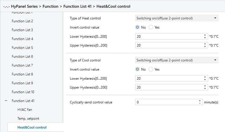
“Switching on/off(use 2-point control) ” interface
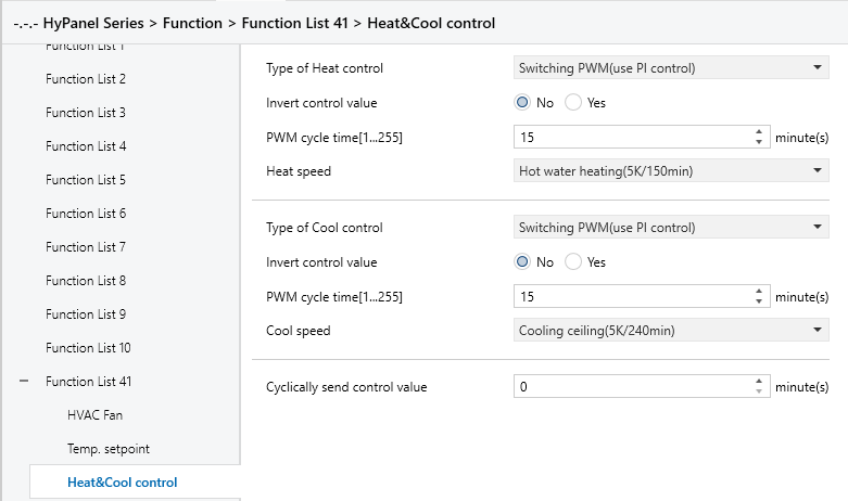
“Switching PWM(use PI control)” interface
“Continuous control(use PI control)” interface
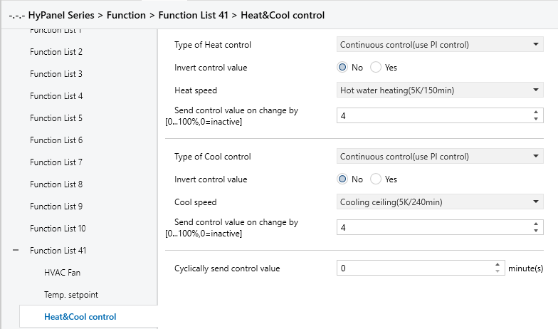
Figure 5.5.3.3: Heat&Cool control interface
Type of Heat/Cool control
Defines the type of object used to switch between heating and cooling modes.
Options:
Switching on/off (use 2-point control)
Switching PWM (use PI control)
Continuous control (use PI control)
Invert control value
Determine the control value sent to the control object is normal or inverted, ensuring compatibility with different valve types.
Options:
No
Yes: After the control value is inverted, it is sent to the bus via the object.
The following two parameters apply to two-point control:
Lower Hysteresis [0..200]*0.1℃
Upper Hysteresis [0..200]*0.1℃
Set temperature hysteresis for HVAC heating or cooling.
Options: 0 ~ 200
In the heating process
Heating stops once the actual temperature (T) exceeds the setpoint temperature plus the upper hysteresis value.
Heating starts when the actual temperature (T) falls below the setpoint temperature minus the lower hysteresis value.
For example, with a lower hysteresis of 1°C and an upper hysteresis of 2°C, and a setpoint temperature of 22°C:
Heating stops if T exceeds 24°C.
Heating starts if T falls below 21°C.
Heating maintains its current state if T is between 21°C and 24°C.
In the cooling process
Cooling stops when the actual temperature (T) falls below the setpoint temperature minus the lower hysteresis value.
Cooling starts when the actual temperature (T) exceeds the setpoint temperature plus the upper hysteresis value.
For example, with a lower hysteresis of 1°C and an upper hysteresis of 2°C, and a setpoint temperature of 26°C:
Cooling stops if T falls below 25°C.
Cooling starts if T exceeds 28°C.
Cooling maintains its current state if T is between 25°C and 28°C.
Note:
Two-point control is a simple method requiring both upper and lower hysteresis values to be set. Consider the following impacts when setting hysteresis temperatures:
A smaller hysteresis range results in less temperature variation but increases bus load due to frequent control value transmissions.
Conversely, a wider hysteresis range reduces switching frequency, but may cause uncomfortable temperature fluctuations.
The following two parameters apply to PI control.
Heating speed
Cooling speed
Sets the response speed of the heating or cooling PI controller. Different response speeds match various environments.
Options:
Hot water heating (5K/150min)
Underfloor heating (5K/240 min)
Electrical heating (4K/100min)
Split unit/ Fan coil unit (4K/90min)
User defined
Options:
Cooling ceiling (5K/240min)
Split unit (4K/90min)
Fan coil unit(4K/90min)
User defined
When the “User defined” is selected in “Heating/Cooling speed”, the following parameters are visible.
Proportional range[10..100]*0.1℃ (P value)
Reset time[0..255]min(I value)
The following parameters are visible when the control type is set to “Switching PWM (use PI control)”.
PWM cycle time [1..255] min
This parameter defines the cycle time for the control object to periodically transmit switching control values. The object sends on/off telegrams depending on the duty cycle of the control value.
For instance, with a set cycle time of 10 minutes and a control value of 80%, the object will send an "on" telegram for 8 minutes and an "off" telegram for 2 minutes in each cycle. This cycle persists continuously. If the control value is changed, the duty ratio of the object's on/off telegram will adjust accordingly, while the period remains constant at the time set by the parameter.
Options: 1 ~ 255
Note:
The PI control values of “Switching PWM (use PI control)” and “Continuous control (use PI control)” are the same. The difference lies in their control object:
The control object of "Continuous control" directly outputs the PI value (1 byte)
The control object of “Switching PWM” outputs an "on/off" control telegram based on the duty cycle of the PI control value.
The following parameters are visible when the control type is set to “Continuous control (use PI control)”.
Send control value on change by [0..100%, 0=inactive]
Specifies the threshold at which a change in the control value prompts its transmission to the bus.
Options: 0 ~ 100. 0=inactive.
Cyclically send control value [0..255]min
Set the time period for cyclically sending the control value to the bus.
Options: 0 ~ 255
In the PI control mode, the recommended predefined control parameters for each PI controller in the heating or cooling system are as follows:
1-Heating system
Heating Type | P Value | I Value (Integration time) | Recommended PI Control Type | Recommended PWM Cycle Period |
Hot water Heating | 5K | 150min | Continuous/PWM | 15min |
Underfloor heating | 5K | 240min | PWM | 15-20min |
Electrical heating | 4K | 100min | PWM | 10-15min |
Split unit | 4K | 90min | PWM | 10-15min |
Fan coil unit | 4K | 90min | Continuous | / |
2-Cooling system
Heating Type | P Value | I Value (Integration time) | Recommended PI Control Type | Recommended PWM Cycle Period |
Cooling ceiling | 5K | 240min | PWM | 15-20min |
Split unit | 4K | 90min | PWM | 10-15min |
Fan coil unit | 4K | 90min | Continuous | / |
3-User defined
When the parameter “Heating/Cooling speed” is set to “User defined”, the values of P (proportionality) and I (integration time) can be set through parameter settings. When adjusting the parameters, refer to the fixed PI value mentioned in the above table. Even slight modifications to these control parameters can result in significantly different control behaviors.
Moreover, it's crucial to set the integration time appropriately. A large integration time value will lead to slow adjustments and subtle oscillations. Conversely, a small integration time value can cause rapid adjustments but may result in oscillations. A value of 0 for the integral time indicates that the integral term is not used.
Settings and effects of User-defined parameters:
Parameter setting | Effect |
K: the proportion range is too small | Rapid adjustment; overshoot will occur |
K: the proportion range is too large | Slow adjustment, without overshoot |
TN: the integration time is too short | Rapid adjustment; oscillation will occur |
TN: the integration time is too long | Slow adjustment, with subtle oscillation |
5.5.3.4 Scene
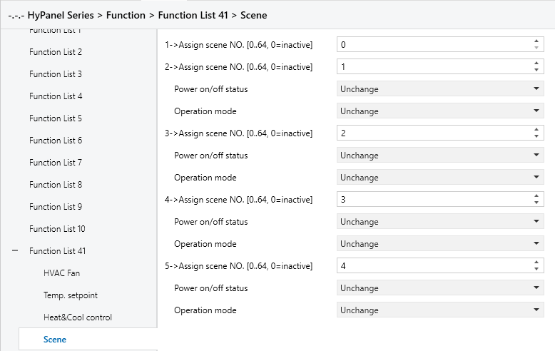
Figure 5.5.3.4: Scene interface
When the Scene function is enabled, this interface is visible and allows to configure 5 scenes with the following parameters:
X->Assign scene NO.[0..64,0=inactive]
Sets the associated scene. When triggered, the configured operation is executed.
Options: 0~64 (0 = Not linked to a scene.)
The following parameters are visible when Assign scene NO. is set to non-zero.
- Power on/off status
Sets the HVAC power status when the associated scene is triggered.
Options:
Unchange
Off
On
- Operation mode
Sets the HVAC operation mode when the associated scene is triggered.
Options:
Unchange
Comfort mode
Standby mode
Economy mode
Frost/heat protection
5.5.4 Function x--Air conditioner
Parameter setting Interface “Function x-- Air conditioner”, as shown in Figure 5.5.4, configures basic control parameters for air conditioners. It applies to two types of air conditioning controls: IR split units and gateway Integrate.
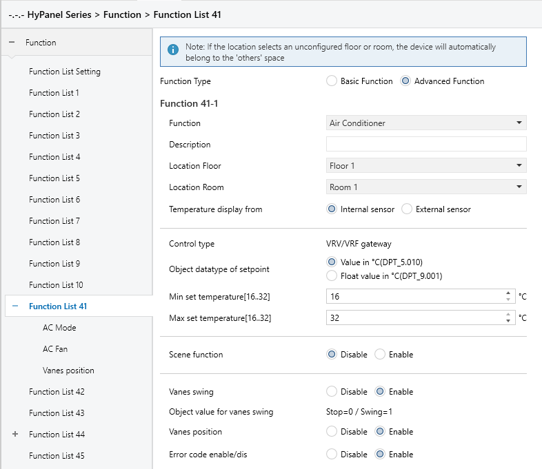
Figure 5.5.4: Function x--Air conditioner interface
Temperature display from
Sets the source of ambient temperature displayed on the AC interface.
Options:
Internal sensor
External sensor
Note:
The AC temperature settings are similar to those for HVAC, except they do not support combined sensors. See Section 5.5.3 for more details.
Time period for request external sensor [0..255]min
Sets the time period for the device to send read requests to the external temperature sensor.
Options: 0 ... 255
Read external sensor after restart
Specifies whether the device reads external sensor data after a reset. Options:
No: The read command waits until the next scheduled polling cycle.
Yes: A read command is sent immediately after restart or programming.
Control type
Sets the air conditioning control method.
Currently available: VRV/VRF Gateway.
Object datatype of setpoint
Specifies the data type used for temperature setpoints.
Options:
Value in ℃ (DPT_5.010)
Float value in ℃ (DPT_9.001)
Min./Max. set temperature [16..32]℃
Specify the range of temperature setpoints. The minimum value must be set lower than the maximum value. If the set temperature exceeds the defined limits, it will be automatically adjusted to fit within the specified range.
Note:
If the minimum temperature exceeds the maximum, the range is set to 16~32℃ by default.
Options:
16℃
17℃
...
32℃
For the setpoint temperature, the minimum value must always be lower than the maximum value. If not met, the parameter cannot be set in ETS.
Scene function
Enables or disables the scene function.
Options:
Disable
Enable: A subpage becomes available to configure triggered actions.
Vanes swing
Enables or disables the swing function. When enabled, the following parameters and objects will be visible.
- Object value for vanes swing
Sets the object value for the vanes swing object. The read-only value is Stop=0 / Swing=1.
- Vanes position
Sets to enable vanes position control. When enabled, the corresponding parameters and objects will be displayed.
Error code enable/dis
Enables or disables the error code function.
Options:
Disable
Enable: Generates three communication objects: Failure Status, Error Code, and Error Text.
5.5.4.1 AC Mode
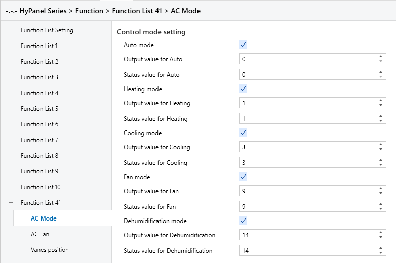
Figure 5.5.4.1: AC Mode interface
Auto/Heating/Cooling/Fan/Dehumidification mode
When these parameters are enabled, the following parameters will be visible.
- Output value for Auto/Heating/Cooling/Fan/Dehumidification
Defines the value sent to switch to each mode.
Options: 0 ~ 255
- Status value for Auto/Heating/Cooling/Fan/Dehumidification
Set status feedback values for each mode. The device updates the mode icon status based on the received feedback value.
Options: 0 ~ 255
5.5.4.2 AC Fan

Figure 5.5.4.2: HVAC Fan interface
Object datatype of 1byte fan speed
Sets the data type of 1byte fan speed.
Options:
Percentage (DPT 5.001)
Fan stage (DPT 5.100)
Output value for Fan speed
Output value for Fan speed off/low/medium/high
Defines the output values to switch to each fan speed level, supporting four fan speeds: Off, Low, Medium, and High.
Depending on the object type of the previous parameter, the options are: 0..255/0..100.
Status feedback for Fan speed
Status value for Fan speed off/low/medium/high
Set the status feedback values for each fan speed. The device will update the displayed fan speed based on the feedback values.
Options: 0..255/0..100.
5.5.4.3 Scene
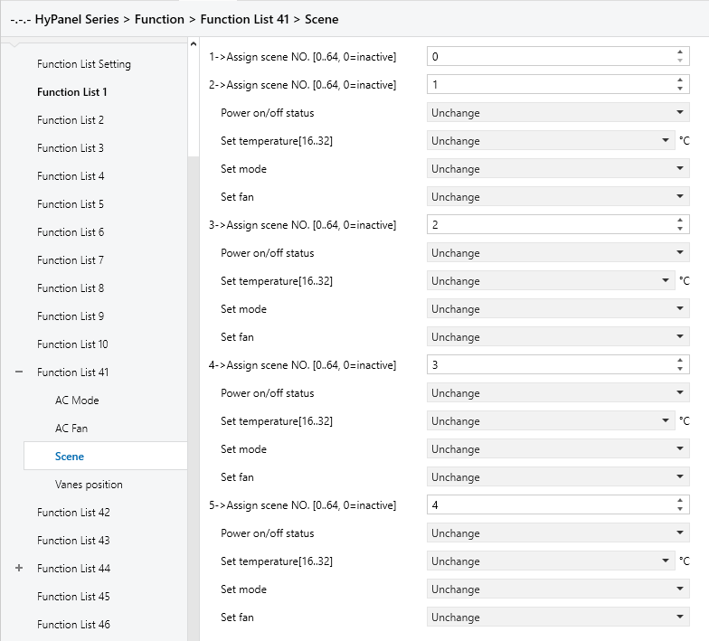
Figure 5.5.4.3: Scene interface
When the Scene function is enabled, this interface is visible and allows to configure 5 scenes with the following parameters:
X->Assign scene NO.[0..64,0=inactive]
Sets the associated scene. When triggered, the configured operation is executed.
Options: 0~64 (0 : Not linked to a scene.)
The following parameters are visible, when Assign scene NO. is set to non-zero.
- Power on/off status
Sets the AC power status when the associated scene is triggered.
Options:
Unchange
Off
On
- Set Temperature[16..32]
Sets the AC preset temperature when the associated scene is triggered.
Options:
Unchange
16℃
17℃
...
32℃
- Set mode
Set the HVAC operation mode when the associated scene is triggered.
Options:
Unchange
Auto mode
Heating mode
Cooling mode
Fan mode
Dehumidification mode
- Set Fan
Set the AC fan speed when the associated scene is triggered.
Options:
Unchange
Auto
Low
Medium
High
5.5.4.4 Vanes position
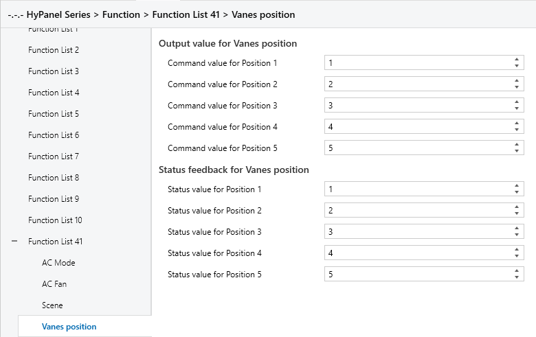
Figure 5.5.4.4: Vanes position interface
When vanes position function is enabled, this interface is visible, offering five selectable vanes positions.
Output value for Vanes position
The following parameters configure the output values sent by the objects “Vanes position 1..5, status” when switching to each vanes position.
“Command value for position 1/2/3/4/5”
Defines the control values corresponding to the five vanes positions.
Options: 0~255
Status feedback for Vanes position
The following parameters configure the status feedback values for each vanes position.
“Status value for position 1/2/3/4/5”
Sets the status feedback values for each vanes position. The device updates the vanes position icon status based on the received feedback value.
Options: 0~255
5.5.5 Function x--Audio control
The parameter setting interface “Function x-- Audio control”, as shown in Figure 5.5.5, configures basic control parameters for the background music players.
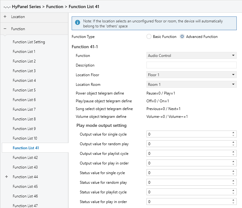
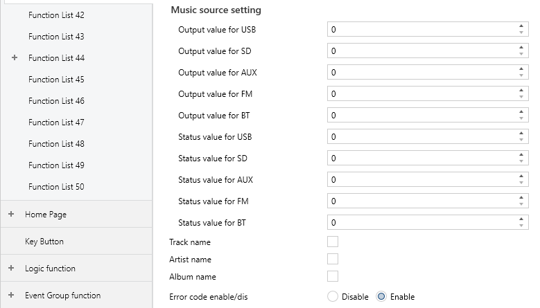
Figure 5.5.5: Function x-- Audio control interface
Power object telegram define
Play/pause object telegram define
Song select object telegram define
Volume object telegram define
These parameters defined the object values of background music commands.
The following parameters define telegrams and feedback values sent when switching to various playback modes.
Play mode output setting
Output value for single cycle/random play/playlist cycle/play in order
Sets the telegram values for each playback modes.
Options: 0 ~ 255
Status value for single cycle/random play/playlist cycle/play in order
Defines the status feedback values for each play mode. The device updates the icon status based on the received feedback value.
Options: 0 ~ 255
The following parameters define telegrams and feedback values sent when switching to each audio source.
Music source setting
Output value for USB/SD/AUX/FM/BT
Sets the telegram values for enabling each audio source.
Options: 0 ~ 255
Status value for USB/SD/AUX/FM/BT
Sets the feedback value for each audio source. The device updates the icon status based on the received feedback values.
Options: 0 ~ 255
Track name
Sets whether to display the track name.
Note:
The character encoding of the track name telegram depends on the selected interface language. When Simplified Chinese is selected, the encoding is UTF-8. For all other languages, ISO 8859 is used.
The artist name and album name telegrams follow the same encoding rules.
Artist name
Defines whether to display the artist name.
Album name
Defines whether to display the album name.
Error code enable/dis
Enables or disables the error code function.
Options:
Disable
Enable: Three group objects “Failure status”, “Error code” and “Error text” will be generated for displaying different data types of error codes.
5.5.6 Function x--Color control type
The parameter setting interface “Color colour type” is as shown in Figure 5.5.6.
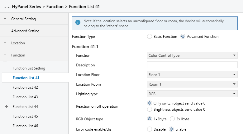
RGB

RGBW
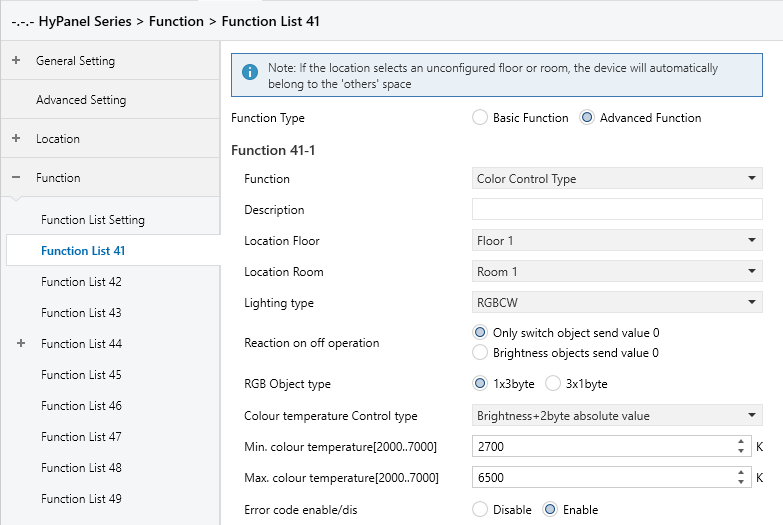
RGBCW
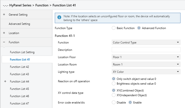
XY Color
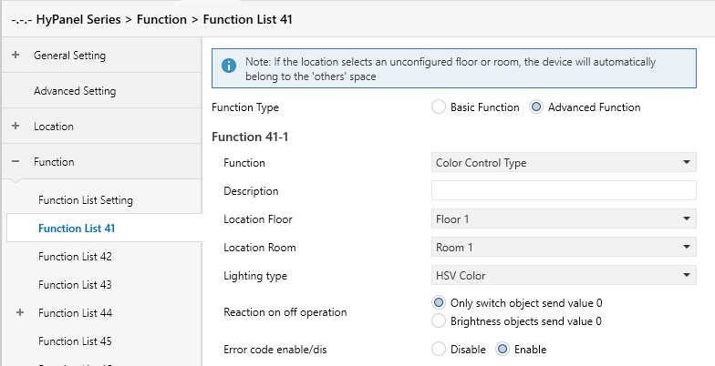
HSV Color

HSVW Color
Figure 5.5.6 Function x-- Color control type interface
Lighting type
Defines the type of RGB light strip
Options:
RGB: For controlling RGB (Red, Green, Blue) lights.
RGBW: For controlling RGB lights with an additional White channel.
RGBCW: For controlling RGB lights with brightness and color temperature adjustment.
XY Color: For RGB lights using XY color control.
HSV Color: For RGB lights using HSV color control.
HSVW Color: For lights using HSV color control with an additional white light channel.
Reaction on "off "operation
Sets whether to send a switch object telegram with value 0, or a brightness object telegram with value 0 when the off/on button is operated.
Options:
Only switch object send value 0
Brightness objects send value 0
RGB object type
Determines the communication object type for RGB or RGBW.
Options:
For RGB type
1x3byte: Adjust RGB dimming through a single 3-byte object.
3x1byte: Adjust RGB dimming through three separate 1-byte objects.
For RGBW type
1x6byte: Adjust RGBW dimming through a single 6-byte object.
4x1byte: Adjust RGBW dimming through four separate 1-byte objects.
Colour temperature Control type
Visible when the light strip type is RGBCW. This parameter is used to set the control method for color temperature.
Options:
Brightness + 2-byte absolute value: Sends a 1-byte brightness value along with a 2-byte absolute color temperature value.
Brightness + 1-byte relative percentage: Sends a 1-byte brightness value and a 1-byte relative color temperature percentage.
Direct (with warm/cool white algorithm): Uses a built-in algorithm to convert the brightness and color temperature values into warm and cool white light levels. Two 1-byte objects are used to control the brightness of the warm and cool white channels.
Status feedback object
Visible when the light strip type is RGBCW and the color temperature control type is set to “Directly (with warm/cool white algorithm)”. Select the status feedback object.
Options:
Brightness+Colour Temperature: Feedback of brightness and color temperature, ensuring consistent data with other panels.
Warm/cool white brightness: Feedback of warm and cool white brightness, ensuring compatibility with actuators.
Min. colour temperature [2000..7000]K
Max. colour temperature [2000..7000]K
These two parameters set the lower and upper threshold limits for the color temperature.
Options: 2000..7000
Note:
When the minimum value exceeds or is equal to the maximum value, the range defaults to 2000K~7000K.
XY control data type
Visible when the light strip type is XY Color. This parameter sets the data type for XY dimming control.
Options:
XY(Combined Object): Control the XY chromaticity diagram using a combined group object parameter.
XY(Independent Object): Control the XY chromaticity diagram using two separate group object parameters.
Error code enable/dis
Enables or disables the error code function.
Options:
Disable
Enable: Three group objects “Failure status”, “Error code” and “Error text” will be generated for displaying different data types of error codes.
5.5.7 Function x--Air Quality display
The parameter setting interface “Function x-- Air Quality display”, as shown in Figure 5.5.7, is used to configure air quality display. It allows for the display settings of AQI, temperature, humidity, PM2.5, PM10, VOC, CO2, illuminance, wind speed and rain. Each interface can display up to 4 data items.
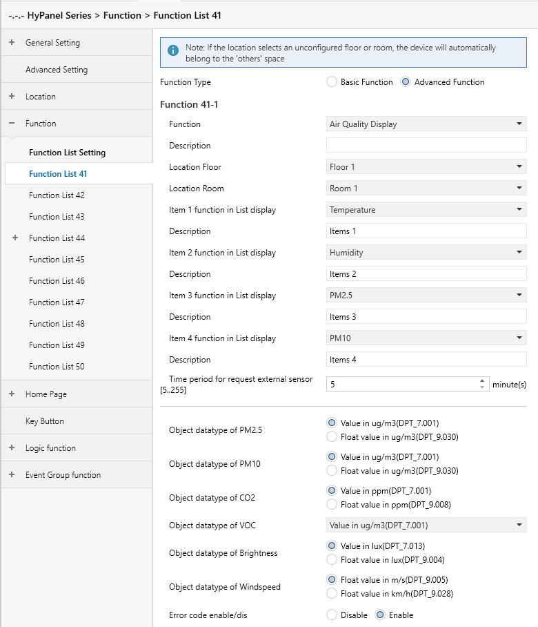
Figure 5.5.7: Function x--Air Quality display interface
Items x(x=1..4) function in List display
Sets the content to be displayed in the list, allowing for a maximum of 4 items.
Options:
Disable
Temperature
Humidity
PM2.5
PM10
CO2
VOC
AQI
Brightness
Wind speed
Rain
These values are detected by external sensors and sent to the device for display. If no data is received, the device screen will remain blank.
Display ranges:
Temperature: -20~100 ℃
Humidity: 0~100 %
PM2.5: 0~500 ug/m3
PM10: 0~600 ug/m3
CO2: 0~5000 ppm
VOC: 0~5000 ppm
AQI: 0~500
Brightness:0~50000 lux
Wind speed:0~50 m/s or 0~150km/h
Rain: Rain or no rain
Description
Sets the name of Air Quality display, with a maximum input of 31 characters, displaying up to 10 Chinese characters.
Time period for request external sensor [5..255]min
Sets the time interval for the device to send read requests to external sensors.
Options: 5.. 255
Object datatype of PM2.5
Sets the data type of PM2.5.
Options:
Value in ug/m3(DPT_7.001)
Float value in ug/m3(DPT_9.030)
Object datatype of PM10
Sets the data type of PM10.
Options:
Value in ug/m3(DPT_7.001)
Float value in ug/m3(DPT_9.030)
Object datatype of CO2
Sets the data type of CO2.
Options:
Value in ug/m3(DPT_7.001)
Float value in ppm(DPT_9.008)
Float value in ug/m3(DPT_9.030)
Object datatype of VOC
Set the data type of VOC.
Options:
Value in ug/m3(DPT_7.001)
Float value in ug/m3(DPT_9.030)
Float value in ppm(DPT_9.008)
Object datatype of Brightness
Sets the data type of Brightness object.
Options:
Value in lux(DPT_7.013)
Float value in lux(DPT_9.004)
Object datatype of Windspeed
Sets the data type of wind speed object.
Options:
Float value in m/s(DPT_9.005)
Float value in km/h(DPT_9.028)
Error code enable/dis
Enables or disables the error code function.
Options:
Disable
Enable: Three group objects “Failure status”, “Error code” and “Error text” will be generated for displaying different data types of error codes.
5.5.8 Function x--Floor heating
The parameter setting interface “Function x--Floor heating”, as shown in Figure 5.5.8, configures the floor heating actuator control settings.
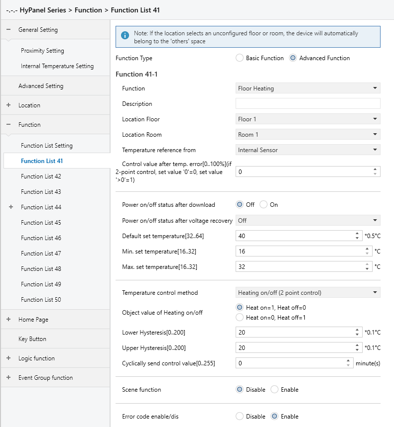
Figure 5.5.8: Function x--Floor heating display interface
Temperature reference from
Sets the source of temperature reference for the floor heating function.
Options:
Internal sensor
External sensor
Internal and External sensor combination
Note:
Temperature settings of floor heating are similar to that of HVAC function. For more details, please refer to Section 5.5.3.
Power on/off status after download
Defines the power on/off status of the floor heating interface after downloading application.
Options:
Off
On
Power on/off status after voltage recovery
Sets the power status of the floor heating interface after bus voltage recovery.
Options:
On: The device powers on in an active state. The interface is operable, and the system determines whether to heat based on the control method.
Off: The device powers on in an inactive state. Only the timer and power icons are operable; all other icons on the interface are disabled.
As before voltage failure: The device restores its previous power state before the outage. If it was on, the system performs internal calculations based on the control method to determine heating output.
Default set temperature[32..64]*0.5℃
Sets the initial temperature when floor heating is activated.
Options: 32.. 64
Min./Max. set temperature[16..32]℃
Specifies the range of set temperature. The minimum value must be set lower than the maximum value. If the set temperature exceeds the defined limits, it will be automatically adjusted to fit within the specified range.
Options: 16.. 32
Temperature control method
Sets the temperature control method. Different control types are for controlling different temperature controllers.
Options:
Heating on/off (use 2-point control)
Heating PWM (use PI control) PWM
Heating continuous control (use PI control)
When the parameter “Temperature control method” is set to “Heating on/off (use 2-point control)”, the following parameters are visible:
In two-point control, heating is turned off when the temperature exceeds one certain set temperature; It is on when it falls below another set temperature.
- Object value of Heating on/off
Defines the trigger values for heating on/off.
Options:
Heat on=1, Heat off=0
Heat on=0, Heat off=1
- Lower Hysteresis [0.. 200]*0.1℃
- Upper Hysteresis [0.. 200]*0.1℃
Sets the lower/upper hysteresis values for the set temperature of floor heating.
Options: 0..200
Note:
Heating stops once the actual temperature (T) exceeds the setpoint temperature plus the upper hysteresis value.
Heating starts when the actual temperature (T) falls below the setpoint temperature minus the lower hysteresis value.
For example, with a lower hysteresis of 1°C and an upper hysteresis of 2°C, and a setpoint temperature of 16°C:
Heating stops if T exceeds 18°C.
Heating starts if T falls below 15°C.
Heating maintains its current state if T is between 15°C and 18°C.
When the parameter “Temperature control method” is set to “Heating PWM (use PI control)” or “Heating continuous control(use PI control)”, the following parameters are visible.
In the PWM switch control, floor heating cyclically switches the valve based on the control value.
In the Continuous control, floor heating regulates the opening and closing of the valve based on the control value.
- Invert control value
Sets whether the control value is sent normally or inverted before being sent to the bus to accommodate the valve type.
Options:
No
Yes: The control value is inverted before being sent to the bus.
- PWM cycle time [1.. 255] min
This parameter is exclusively accessible when the "Temperature Control Method" is configured as "Heating PWM (use PI control)". It defines the cycle time for the control object to periodically transmit switching control values. The object sends on/off telegrams depending on the duty cycle of the control value.
For instance, with a set cycle time of 10 minutes and a control value of 80%, the object will send an "on" telegram for 8 minutes and an "off" telegram for 2 minutes in each cycle. This cycle persists continuously. If the control value is changed, the duty ratio of the object's on/off telegram will adjust accordingly, while the cycle time remains constant.
Options: 1.. 255
- Heating speed
Specifies the response speed of the heating PI controller. Different response speeds are applicable for different environments.
Options:
Hot water heating (5K/150min)
Underfloor heating (5K/240 min)
Electrical heating (4K/100min)
User defined: Once selected, the following two parameters are visible.
- Proportional range[10.. 100]*0.1℃ (P value)
- Reset time[0.. 255]min (I value)
They set the control values of PI controller. For more details about 2-point and PI control methods, please refer to Section 5.5.3.
Cyclically send control value [0..255]min
Defines the interval for cyclically sending control values to the bus.
Options: 0.. 255
Scene function
Enables or disables the scene functions of the floor heating.
Options:
Disable
Enable: The Scene function subpage is visible to configure the triggered actions.
Error code enable/dis
Enables or disables the error code function.
Options:
Disable
Enable: Three group objects “Failure status”, “Error code” and “Error text” will be generated for displaying different data types of error codes.
x->Assign scene NO. [1..64,0=inactive], x=1~5
Sets the scene number.
Options: 0.. 64,0=inactive
Power on/off status
Sets the power on/off status of scene x for the floor heating interface.
Options:
Off
On
5.5.8.1 Scene
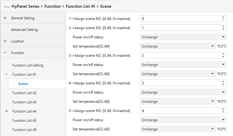
Figure 5.5.8.1: Scene interface
When the Scene function is enabled, this interface is visible and allows to configure 5 scenes with the following parameters:
X->Assign scene NO.[0..64,0=inactive]
Sets the associated scene. When triggered, the configured operation is executed.
Options: 0~64 (0 means not linked to a scene.)
The following parameters are visible, when Assign scene NO. is set to non-zero.
- Power on/off status
Sets the power on/off status of underfloor heat when the associated scene is triggered.
Options:
Unchange
Off
On
- Set temperature[16..32]
This is visible when “Assign scene NO.” is set to “non-zero”. It specifies the preset temperature for scene x.
Options:
Unchange
32*0.5℃
33*0.5℃
...
64*0.5℃
5.5.9 Function x-- Ventilation System
Parameter setting interface “Function x - Ventilation System”, as shown in Figure 5.5.9, sets the parameters for the ventilation system controlling.
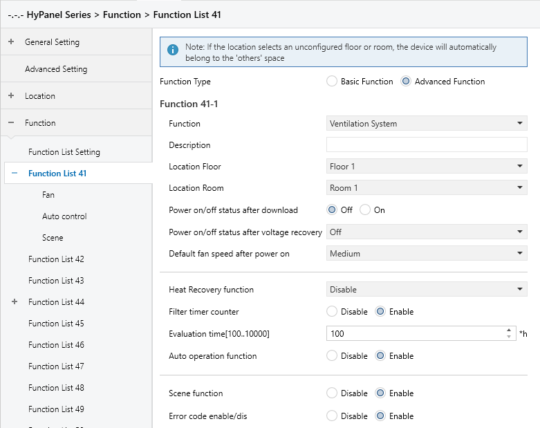
Figure 5.5.9: Ventilation system display interface
Power on/off status after download
Sets the power on/off status of the ventilation interface after the application is downloaded.
Options:
Off
On
Power on/off status after voltage recovery
Set the power on/off status of the ventilation interface after the power is restored.
Options:
On: When power is restored, the device will be in the On state, and the interface will be operational.
Off: When power is restored, the device will be in the Off state. Other icons in the interface are not operational except for filter reset and on/off icons.
As before voltage failure: Upon power restoration, the device returns to its status prior to power off.
Default fan speed after power on
Sets the initial fan speed when the ventilation is turned on.
Options:
Off
Low
Medium
High
Heat Recovery function
Enables or disables the heat recovery function.
Options:
Disable
Disable=0/Enable=1
Disable=1/Enable=0
If the last two options are selected, the heat recovery function defaults to enable upon system power-on. If not enabled, the heat recovery function is uncontrollable.
Filter timer counter
Defines whether enable the filter timer function.
When enabled, the following parameter is visible.
- Evaluation time[100..10000]h
Sets the service life of the filter.
Options: 100..10000
When the filter usage time exceeds the set value, a filter cleaning alert will be sent to the HyPanel.
The usage time can be reset via the “Filter Timer Reset” object.
The usage duration is tracked via the “Filter Timer Counter” object, measured in hours. When the value changes, it is sent to the bus. The counter value can also be modified via the bus.
Auto. operation function
Defines whether enable the automatic fan speed operation interface.
When enabled, the fan speed is automatically adjusted based on air quality values such as PM2.5 or CO2, with sensor data retrieved from the bus.
A telegram value of 1 activates automatic fan speed control, while 0 deactivates it.
Scene function
Enables or disables the scene function.
Options:
Disable
Enable: The Scene function subpage becomes visible, where operations executed by triggering linked scenes can be configured.
Error code enable/dis
Enables or disables the error code function.
Options:
Disable
Enable: Three group objects “Failure status”, “Error code” and “Error text” will be generated for displaying different data types of error codes.
5.5.9.1 Fan
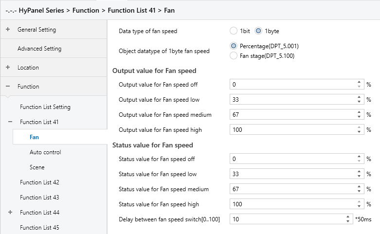
Figure 5.5.9.1: Fan interface
Data type of fan speed
Sets the data type of the fan speed.
Options:
1bit
1byte
The following parameters are visible when the “Data type of fan speed” is “1bit”.
- Object value for Fan speed off/low/medium/high
Defines the values sent to switch to each fan speed, simultaneously transmitted by three 1-bit objects.
Options:
No.1=0, No.2=0, No.3=0
No.1=1, No.2=0, No.3=0
No.1=0, No.2=1, No.3=0
No.1=1, No.2=1, No.3=0
No.1=0, No.2=0, No.3=1
No.1=1, No.2=0, No.3=1
No.1=0, No.2=1, No.3=1
No.1=1, No.2=1, No.3=1
The following parameters are visible when the “Data type of fan speed” is “1byte”.
- Object datatype of 1byte fan speed
Defines the object datatype of 1byte fan speed
Options:
Percentage (DPT 5.001)
Fan stage (DPT 5.100)
Output value for Fan speed
- Output value for Fan speed off/low/medium/high
Defines the values sent to switch to each fan speed, supporting four types: off, low, medium, high.
Options: 0..255/0..100
Status feedback for Fan speed
- Status value for Fan speed off/low/medium/high
Sets the status feedback values for each fan speed. The device updates the fan speed status based on the received feedback values.
Options: 0..255/0..100
Delay between fan speed switch [0..100]*50ms
Set a delay in changing fan speeds, considering the technical specifications of the fan.
Options: 0..100
When switching fan speeds, the fan speed should first be turned off. Then, after a delay, the fan speed can be turned on before the telegram is sent to the bus. If the delay time is set to 0, the fan will switch directly to the next speed without turning off first.
5.5.9.2 Auto.Control
When the auto operation is activated, the ventilation system will automatically adjust the fan speed based on the control values. The parameters visible are available when the ventilation system's automatic operation is enabled. The parameter setting interface is displayed as below.
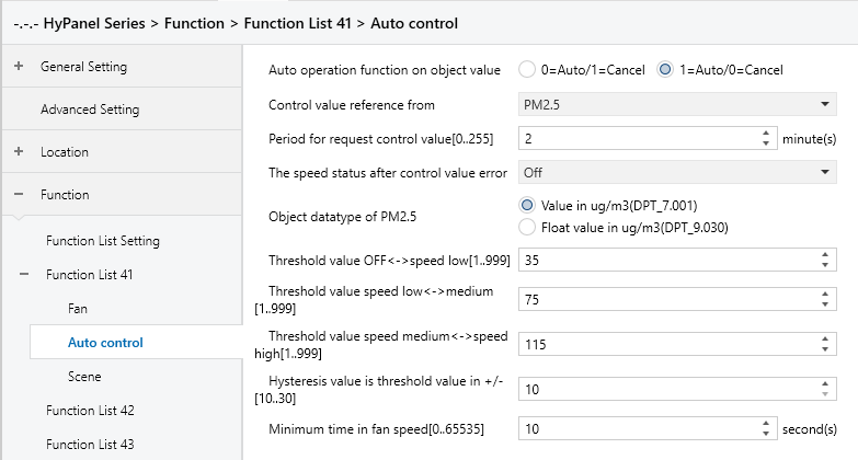
Figure 5.5.9.2-1: Auto.Control_PM 2.5 interface
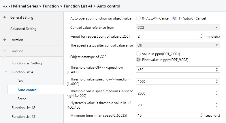
Figure 5.5.9.2-2: Auto.Control_CO2 interface
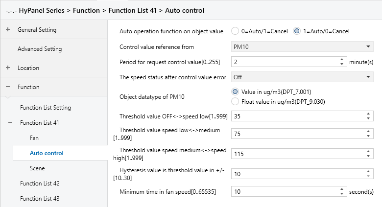
Figure 5.5.9.2-3: Auto.Control_PM10 interface
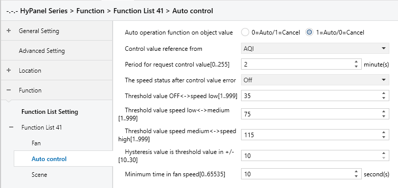
Figure 5.5.9.2-2: Auto.Control_AQI interface
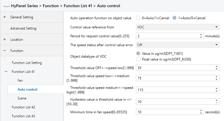
Figure 5.5.9.2-2: Auto.Control_VOC interface
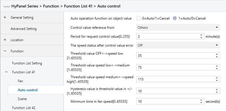
Figure 5.5.9.2-2: Auto.Control_Others interface
Auto operation function on object value
Sets the telegram value for activating automatic operation.
Options:
0=Auto/1=Cancel: Activates automatic operation when the object “Automatic function, In/Out” receives a telegram value of 0 and cancels automatic operation when it receives 1.
1=Auto/0=Cancel: Activates automatic operation when the object “Automatic function, In/Out” receives a telegram value of 1 and cancels automatic operation when it receives 0.
Note:
After power-on, automatic operation is not activated by default.
Control value reference from
Sets the source of the control value.
Options:
PM2.5
CO2
PM10
AQI
VOC
Others
Period for request control value [0..255] Min
Sets the time period for the device to send control value read requests to external sensors.
Options: 0..255
The speed status when the control value error
Sets the default fan speed when a control value error occurs.
Options:
Off
Low
Medium
High
Note:
If attempts to read control values from external sensors yield no response, it will be considered a sensor malfunction and a control value error.
Object datatype of PM2.5
Selects the type for PM2.5, which determines the object type and should be chosen according to the type of PM2.5 sensor in use.
Options:
Value in ug/m3(DPT_7.001)
Float value in ug/m3(DPT_9.030)
DPT_7.001: Applicable for integer values
DPT_9.030: Applicable for floating-point values
Object datatype of CO2
Sets the data type for CO2, which determines the object type and should be chosen according to the type of CO2 sensor in use.
Options:
Value in ppm(DPT_7.001)
Float value in ppm(DPT_9.008)
DPT_7.001: Applicable for integer values
DPT_9.008: Applicable for floating-point values
Object datatype of PM10
Sets the data type for PM10, which determines the object type and should be chosen according to the type of PM10 sensor in use.
Options:
Value in ug/m3(DPT_7.001)
Float value in ug/m3(DPT_9.030)
DPT_7.001: Applicable for integer values
DPT_9.030: Applicable for floating-point values
Object datatype of VOC
Sets the data type for VOC, which determines the object type and should be chosen according to the type of VOC sensor in use.
Options:
Value in ug/m3(DPT_7.001)
Float value in ug/m3(DPT_9.030)
DPT_7.001: Applicable for integer values
DPT_9.030: Applicable for floating-point values
Threshold value OFF<-->speed Low[1..999]/[1..4000] /[1..65535]
Defines the threshold value for turning off the fan and running at low speed.
Options: 1…999/1...4000/1...65535
If the control value is greater than or equal to the threshold value, the fan will run at low speed. If the control value is less than this threshold value, the fan will be turned off.
Threshold value speed low<-->medium[1..999]/[1…4000] /[1..65535]
Defines the threshold value for switching to the medium-level fan speed. If the control value is greater than or equal to the threshold value, the fan will run at medium speed.
Options: 1…999/1...4000/1...65535
Threshold value speed medium<-->high[1..999]/[1…4000] /[1..65535]
Defines the threshold value for switching to the high-level fan speed.
If the control value is greater than or equal to this threshold value, the fan runs at high speed.
Options: 1…999/1...4000/1...65535
Note:
The controller evaluates thresholds in ascending order. The correct execution of the function is guaranteed only under this condition:
First check → OFF -> Low fan speed threshold → Low fan speed -> Medium fan speed threshold → Medium fan speed -> High fan speed threshold.
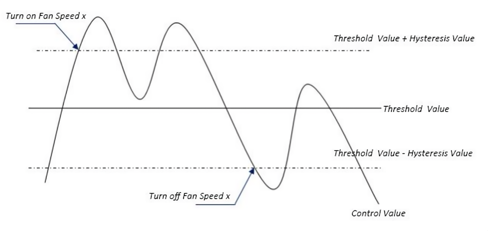
Hysteresis value is threshold value in +/- [10..30]/[100..400] /[1..65535]
Specifies the hysteresis value for the threshold, which helps prevent unnecessary fan actions when the control value fluctuates near the threshold.
Options: 10..30/100..400/1...65535
For instance, with a control value of PM2.5, a hysteresis value of 10, and a threshold value of 35, the upper threshold limit would be 45(threshold value+hysteresis value), and the lower threshold limit would be 25(threshold value-hysteresis value).
When the control value falls between 25 and 45, the fan's operation state remains unchanged. Changes occur only when the control value is below 25, or equals 45 or higher. As shown in the following figure:
Note:
When hysteresis is enabled and there is overlapping of thresholds, the fan's action is as follows:
(1) Hysteresis determines the control point for fan speed transition.
(2) New fan speed is determined by control value and threshold without considering hysteresis.
For example, with PM2.5:
OFF <-> Low fan speed threshold is 20.
Low <-> Medium fan speed threshold is 40.
Medium <->High fan speed threshold is 70.
Hysteresis is set to 10.
a. When the fan speed increases from OFF
The OFF status changes when the control value reaches 30 (≥20+10).
If the received control value is 41, the fan speed goes to Medium (41 falls between 40 and 70, and hysteresis is not considered). In this case, the Low speed is bypassed.
If the received control value is 39, the fan speed will be Low (39 falls between 20 and 40, and hysteresis is not considered).
b. When the fan speed decreases from the high-level:
The high-speed status changes when the control value is at 60 (<70-10).
If the received control value is 39, the fan speed becomes Low (39 falls between 20 and 40, and the hysteresis is not considered at this point). In this case, the Medium speed is bypassed.
(3) When the control value is 0, the fan must be OFF status.
Minimum time in fan speed [0…65535]s
Specifies the minimum time interval for the fan to maintain its current speed before speed changes, ensuring a minimum operating time for each fan speed. The fan must wait for this duration before changing its speed. If it runs at the current speed for longer than the set minimum time, it can quickly switch to another speed.
Options: 0..65535 (0: No minimum running time, but the delay in switching fan speed should be considered.)
Note:
This minimum time setting only applies to Auto mode.
5.5.9.3 Scene
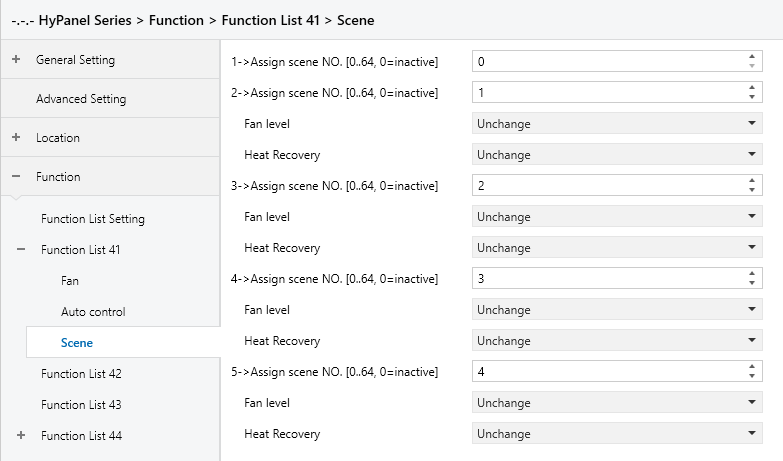
Figure 5.5.9.3: Scene interface
When the Scene function is enabled, this interface is visible and allows to configure 5 scenes with the following parameters:
X->Assign scene NO.[0..64,0=inactive]
Sets the associated scene. When triggered, the configured operation is executed.
Options: 0~64 (0 means not linked to a scene.)
The following parameters are visible, when Assign scene NO. is set to “non-zero”.
- Fan level
Sets the fan level of ventilation system when the associated scene is triggered.
Options:
Unchange
Off
Low
Medium
High
- Heat recovery
Sets the heat recovery of ventilation system when the associated scene is triggered.
Options:
Unchange
Off
On
5.5.10 Function x-- Energy Metering display
The Energy Metering parameter settings interface, as shown in Figure 5.5.10, configures the display of energy metering values, including current, voltage, power, and energy consumption. Each interface supports up to 4 display items.
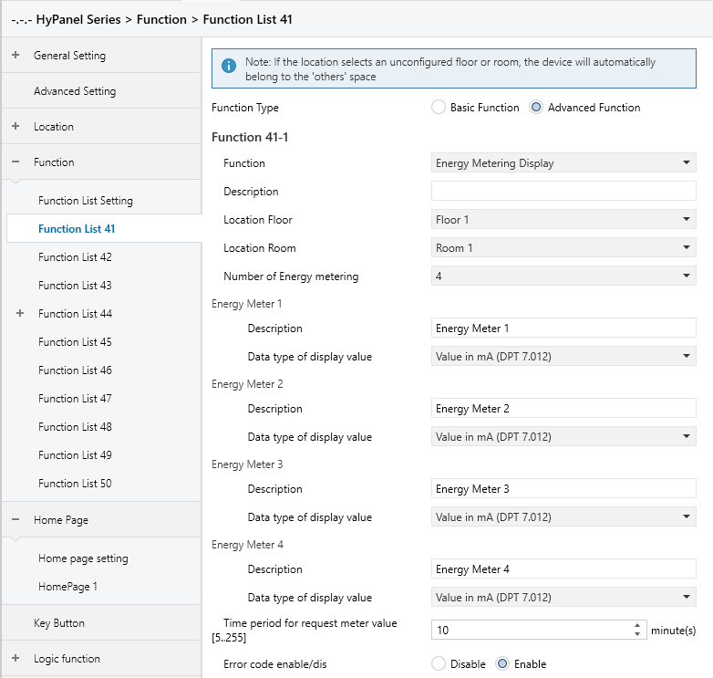
Figure 5.5.10: Function x --Energy Metering display interface
Number of Energy metering
Specifies the number of items to be displayed on the energy page, with a maximum of 4 display items.
Options: 1/2/3/4
Description
Defines the name of the energy display item, with a maximum input of 31 characters, displaying up to 10 Chinese characters.
Data type of display value
Sets the data type of the energy display item.
Options:
Value in mA(DPT 7.012): For mA current which is integer value
Float value in mV(DPT 9.020): For mV voltage which is floating point value
Float value in mA(DPT 9.021) : For mA current which is floating point value
Float value in kW(DPT 9.024): For kW power which is floating point value
Value in Wh(DPT 13.010): For Wh energy which is integer value
Value in kWh(DPT 13.013): For kWh energy which is integer value
Float value in A(DPT 14.019): For A current which is floating point value
Float value in V(DPT 14.027): For V voltage which is floating point value
Float value in W(DPT 14.056): For W power which is floating point value
Time period for request meter value[5..255]Min
Sets the time period for the device to request meter value readings from the external metering device.
Options: 5 .. 255
Error code enable/dis
Enables or disables the error code function.
Options:
Disable
Enable: Three group objects “Failure status”, “Error code” and “Error text” will be generated for displaying different data types of error codes.
5.5.11 Function x-- Advanced switch
The Advanced Switch parameter settings interface, as shown in Figure 5.5.11, configures the display functions of the advanced switch. It allows setting the number of keys, key display type, and the text or icon for each key.
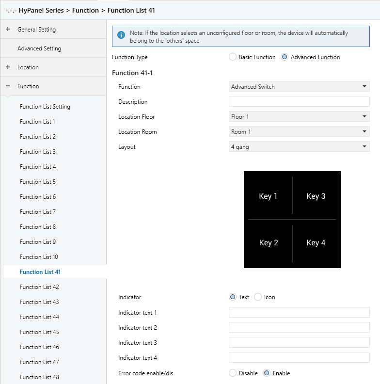
Figure 5.5.11: Function x --Advanced switch interface
Layout
Specifies the number of keys for the advanced switch.
Options:
2 gang
3 gang
4 gang
6 gang
8 gang
The number of thumbnails and key text or icon setting options generated below will match the selected number of keys.
Indicator
Determines the display type for the advanced switch keys.
Options:
Text: Shows the configured text on the advanced switch key.
Icon: Displays the configured icon on the advanced switch key.
The following parameters are visible when “Text” is selected for Indicator:
- Indicator text x
Sets the display content for text-type keys. A maximum of 13 characters can be entered, and up to 4 Chinese characters can be displayed.
Note:
The display content length of this parameter is limited based on the selected Layout quantity, as restricted by HyPanel itself.
The following parameters are visible when “Icon” is selected for Indicator:
- Indicator icon x
Sets the icon for icon-type keys.
Options:
Leave home
Dinner
Go home
Shade
AC
Lighting
Music
Sleep
Coffee
Floor heating
Gym
Reading
Scenario