About This Manual
This guide is intended for system administrators who need to manage personnel, doors, devices, and access control configurations on Akuvox ACMS Pro (Access Control Management System).
This manual applies to the ACMS Pro Server version 1.0.0.4.
Product Overview
With ACMS Pro, you can:
Achieve data synchronization between ACMS Pro and connected device(s).
Manage personnel and department information for access control.
Customize access schedules and authority groups for door access, and monitor logs for security purposes.
Import and export system data for convenient data sharing and system migration.
Compatible Models and Minimum Versions
A01/A02: 101.30.11.118
A03: 103.30.11.107
E16V2: 216.30.12.15
Part 1: Installation and Login
Before You Begin
Before installation, make sure that the following requirements are met:
Windows 7 operating system or above.
Only one ACMS Pro is allowed in the same LAN (Local Area Network).
No SDMC or other ACMS software are turned on your personal computer or on other personal computers in the same network.
The device(s) to be managed are not connected to Akuvox SmartPlus.
These requirements help avoid configuration conflicts caused by multiple management platforms controlling the same devices. If a device is currently registered with SDMC or SmartPlus, remove it from that platform first before adding it to ACMS Pro.
Install ACMS Pro Server Component
The server component should be installed on the computer that will act as the system's host — it handles communication with devices and stores all configuration data. The client component can be installed on the administrator's day-to-day computer for accessing the management interface. Both can be installed on the same computer, or on separate computers (in which case the client connects to the server via its IP address).
Decompress the ACMS Pro.zip file.
Double-click the setup.exe file.
Click Yes in the pop-up window to continue the installation.
Accept the terms of the license agreement.
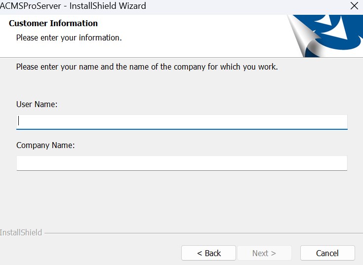
Enter Username and Company Name before clicking Next.
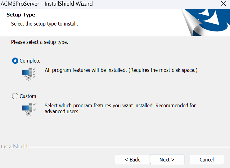
Choose the setup type (Complete or Custom) and click Next.
Click Install.
Note
The ACMS Pro installation path should use English characters.
After the installation is completed, the AcmsProServerManage icon will appear on your desktop.
Set up ACMS Pro Server Manage Software
This software is installed alongside the server component and manages three services:
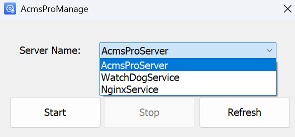
ACMS Pro Server: Facilitates two-way communication between ACMS Pro and the devices for data transmission. This service must be running for ACMS Pro to function correctly.
WatchDog Service: Runs automatically by default after installation. It monitors the status of the ACMS Pro Server and attempts automatic recovery if issues are detected.
Nginx Service: Acts as a reverse proxy, handling HTTPS request forwarding to ensure secure connections for the web management portal, PC Client, and HTTP API calls. This service should also remain running.
Recommended startup order
Confirm that ACMS Pro Server (the core service) is running first, then check that WatchdogService and NginxService are also running. If a service shows an error, click Refresh to update its status, then try Start again.
Access ACMS Pro
Once the server component is installed, you can access the ACMS Pro management interface in two ways, using the same Server Address — the IP address or domain name of the computer hosting the ACMS Pro server:
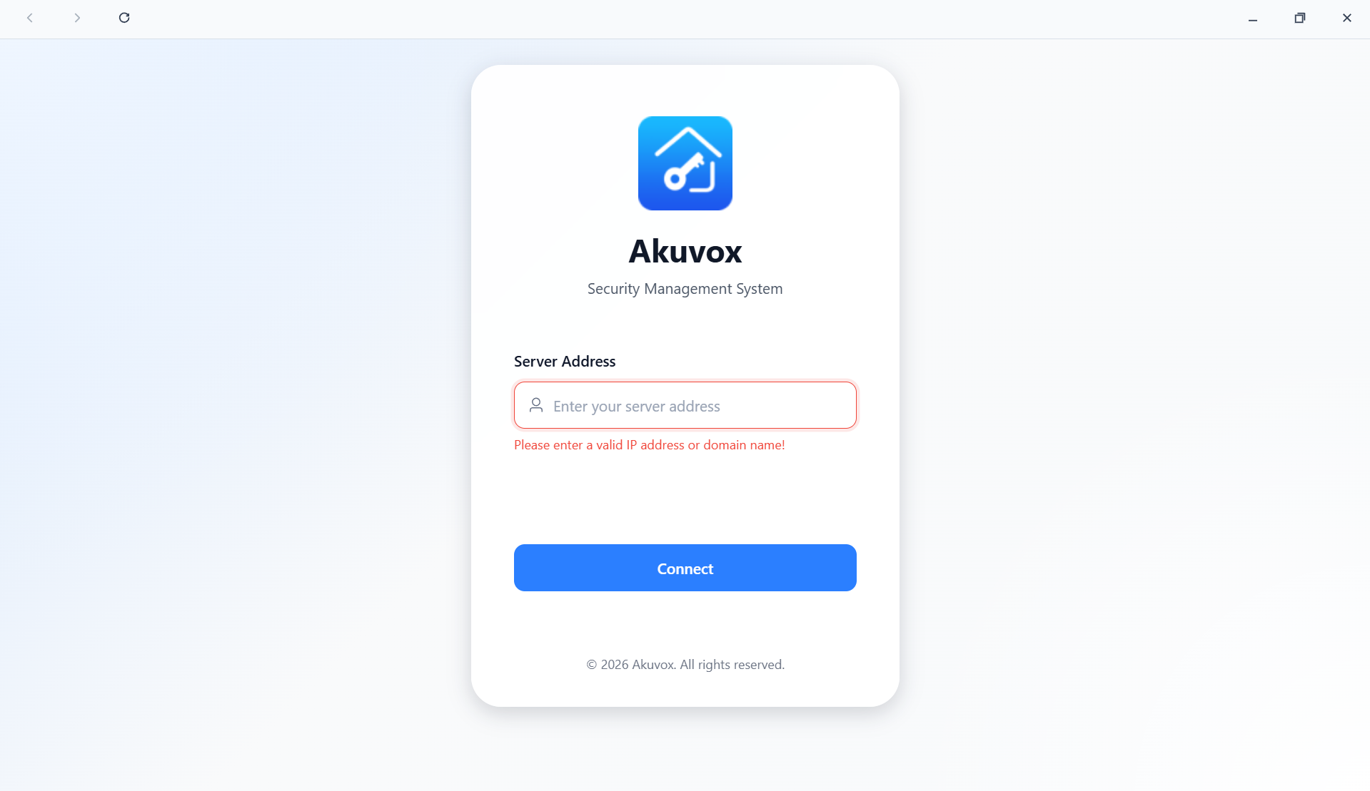
PC Client: Open the installed ACMS Pro client, enter the Server Address, and click Connect.
Web Browser: Enter the Server Address directly into your browser's address bar — no client installation required.
Both methods connect to the same server and provide identical functionality. If you plan to manage ACMS Pro entirely through a browser, you can skip installing the PC Client and go straight to logging in.
Install the Client Application(ACMS Pro)
Double-click the ACMS Pro setup.exe file.
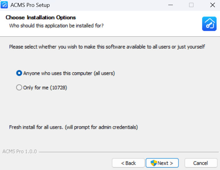
Choose the installation option.
Anyone who uses this computer (all users): Available to all users of the computer.
Only for me: Available only to the current user.
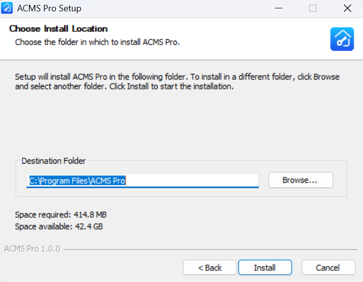
Choose the installation location.
Click Install.
After installation completes, the ACMS Pro icon will appear on your desktop.
Part 2: Login and Account Setup
Initial Setup
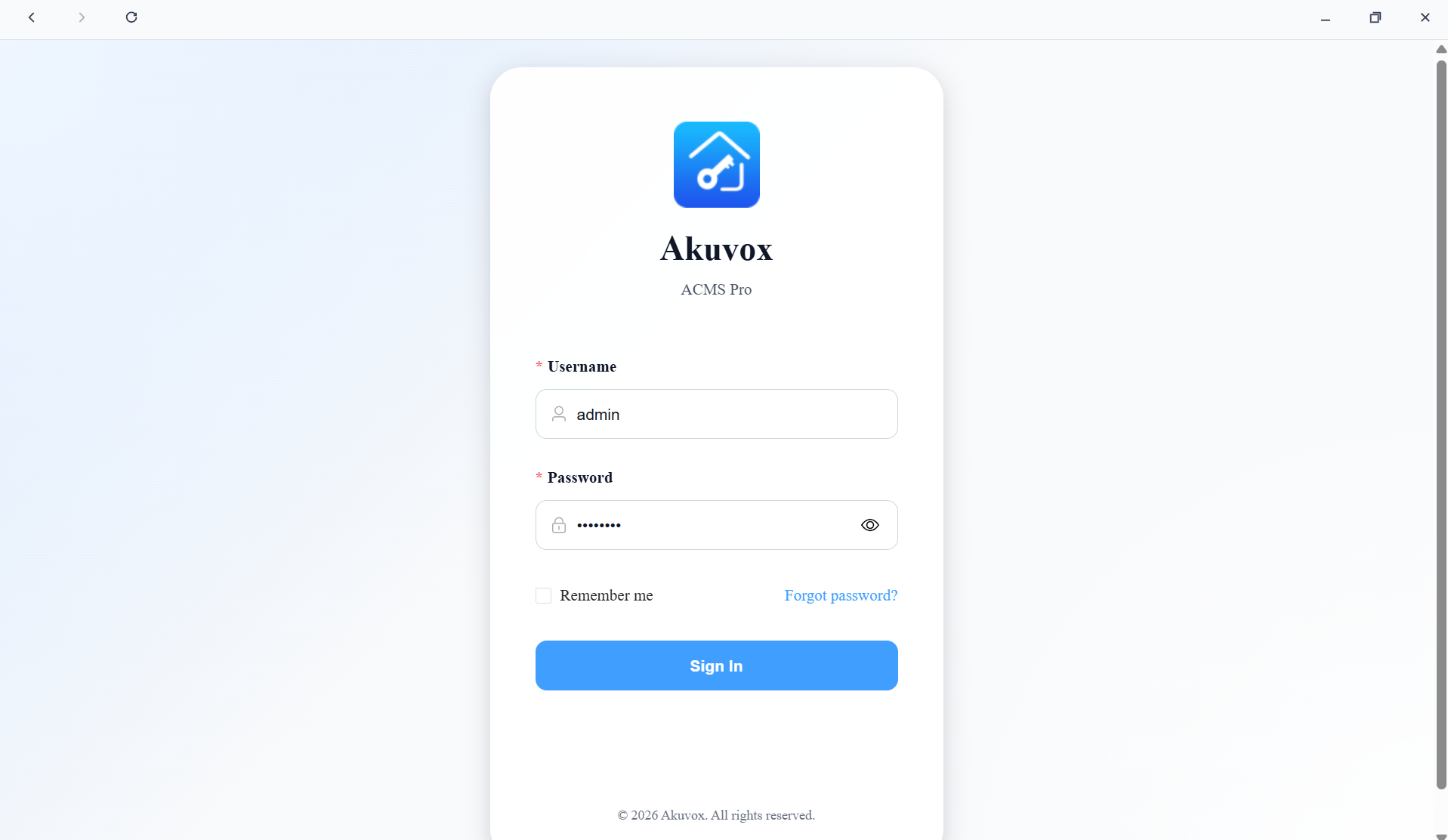
Open the ACMS Pro client, enter the Server Address.
Click Connect.
Log in with the default credentials:
Username:
adminPassword:
admin123
Agree to the Privacy Policy and Terms of Service before continuing.
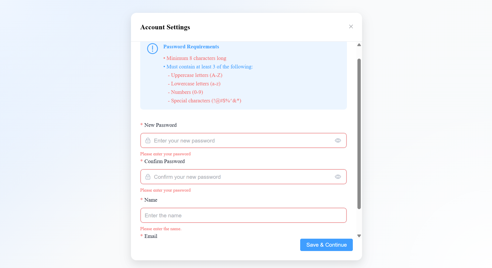
Set the new password for login.
Enter your Name and Email (used for password recovery).
You will be returned to the login page. Log in again with the username
adminand your new password.
Forgot Password
On the login page, click Forgot Password.
Enter the email address associated with your account.
Click Send Reset Link.
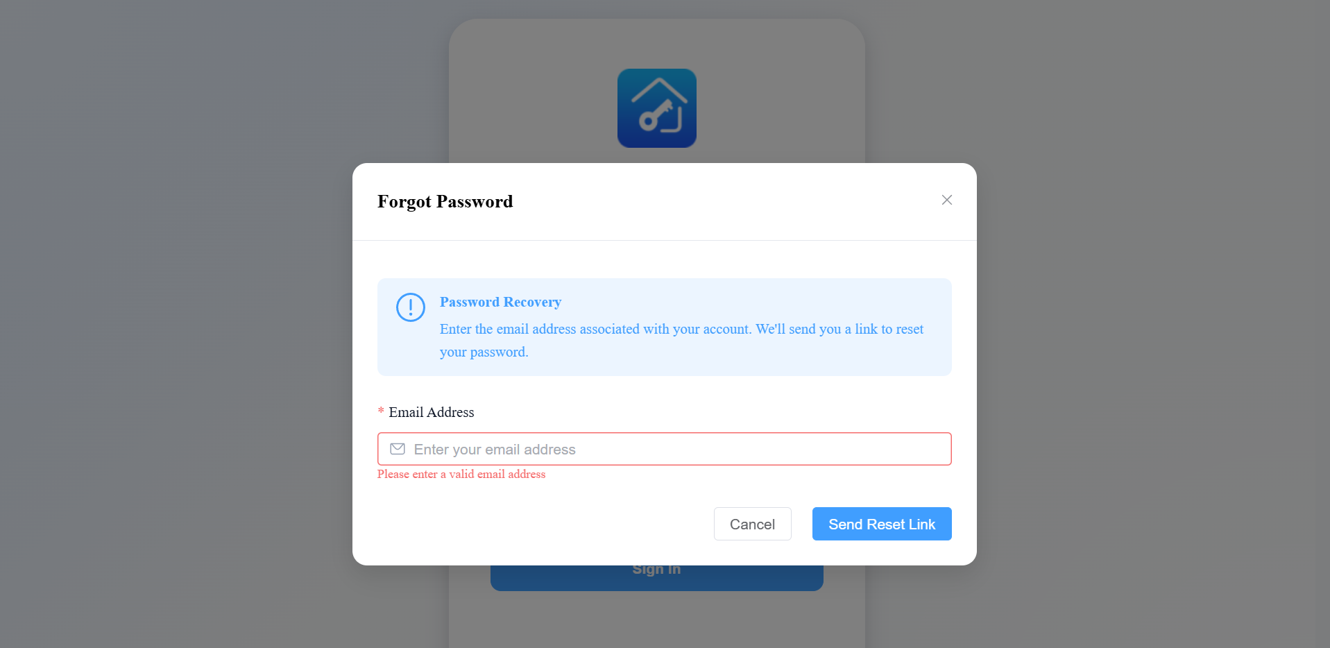
A password reset link will be sent to your email. Follow the instructions in the email to reset your password.
Note
If the SMTP server has not been configured (see the System Management section), the system will not be able to send the reset email.
Part 3: Getting Started
Pre-Configuration Checklist
Before starting configuration, complete the following checks to avoid common issues such as devices not being detected or failing to sync:
Device firmware: Confirm the device's firmware version supports ACMS Pro standalone mode (no connection to SDMC). If the version is too old, update the device firmware first.
Network connectivity: Make sure the device is powered on and connected to the same LAN as the ACMS Pro server. You can verify this with a ping test.
Conflict check: Confirm no SDMC or other ACMS instance is running in the same network, and that the device is not connected to Akuvox SmartPlus — otherwise the device may not be discoverable or may fail to sync correctly with ACMS Pro.
Note
Note down the MAC addresses of devices you plan to add. If you're planning a bulk personnel import, plan your department structure in advance.
Recommended Configuration Workflow
For a smooth initial setup, follow this order:
Add Devices — register your door phones / access control terminals.
Configure Doors — completed as part of adding a device: set up readers, exit buttons, door sensors, etc.
Create Departments — organize your personnel structure.
Create Access Groups — define who can open which doors, and when.
Add Personnel — enter personnel details, assign credentials (PIN/RF Card/Face ID/Fingerprint), and assign access groups.
[Optional] Configure Advanced Access Control — Interlock, Anti-Passback, Emergency Action.
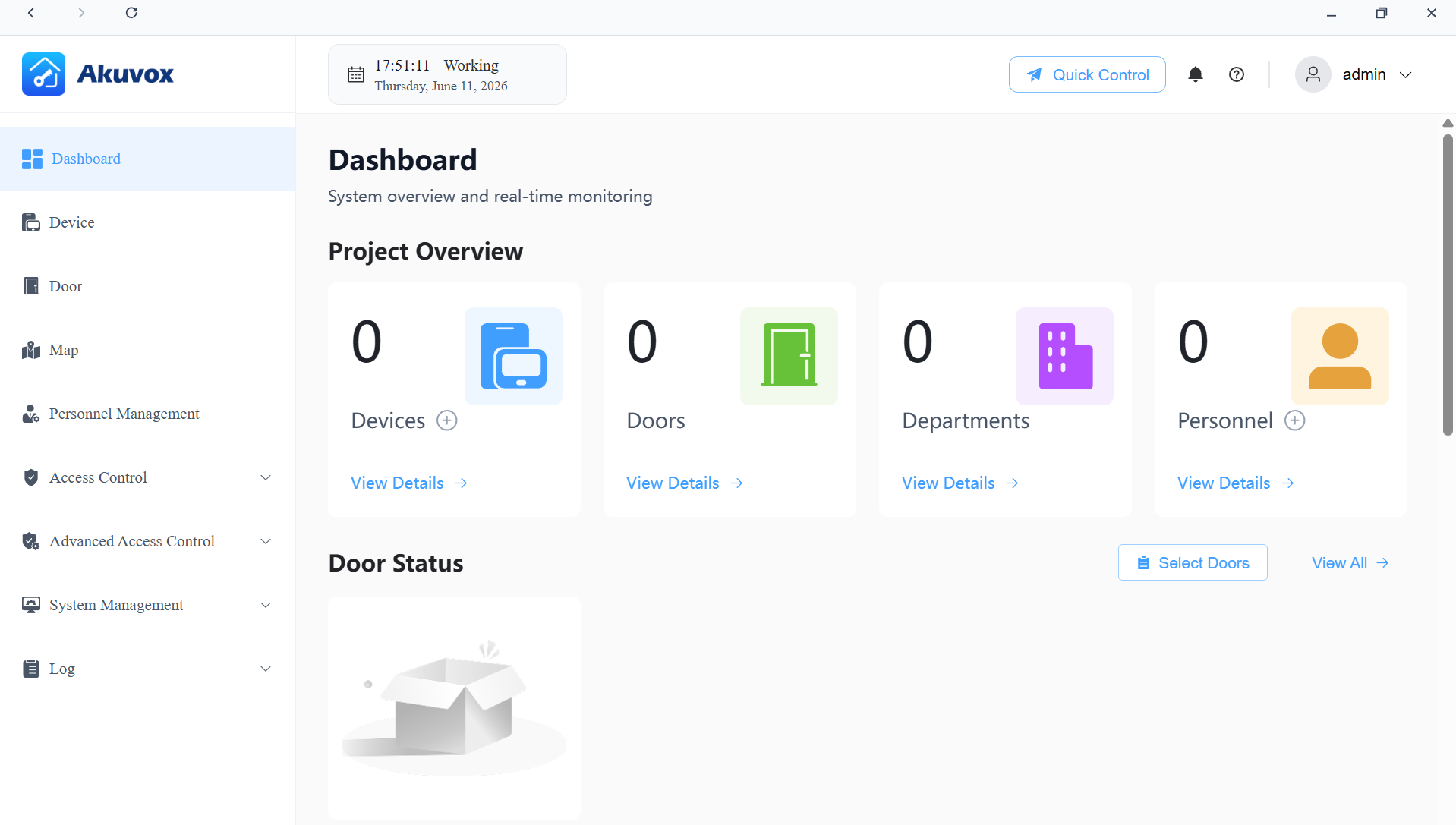
Dashboard Overview
The project management dashboard gives you an overview of the project.
The four cards at the top show the current number of devices, doors, departments, and personnel. Click View Details on any card to jump directly to the corresponding module.
The Door Status section lets you select specific doors to check their real-time online status and current mode (Locked / Hold Open / Lockdown).
Left Menu Description:
Modules | Description |
Dashboard | Have a quick grasp of the project management portal. |
Device | Add, edit, and configure devices. |
Door | Manage door quick control and access schedules. |
Map | Visualize and manage devices through interactive floor plans and maps. |
Personnel Management | Manage departments and personnel information. |
Access Control | The module contains:
|
Advanced Access Control | The module contains:
|
System Management | Includes Data Backup, System Settings, Permission Management, Account Management, System Monitoring, and Certificate Management. |
Logs | Check various logs, including door logs, call history, motion logs, and alarm records. |
Part 4: Device Management
Add a Single Device
ACMS Pro offers two ways to add a device:
Scan Device: Best when the device is on the same LAN as the server — the system automatically discovers available devices and lists them, making this the recommended method.
Add Device (manual): Use this when the device is not on the same LAN (e.g., a different subnet), or when scanning doesn't find the device. You'll need to enter the device's information manually.
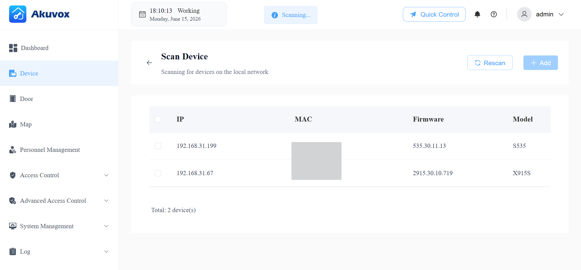
Add by Scanning
Click Device > Scan Device.
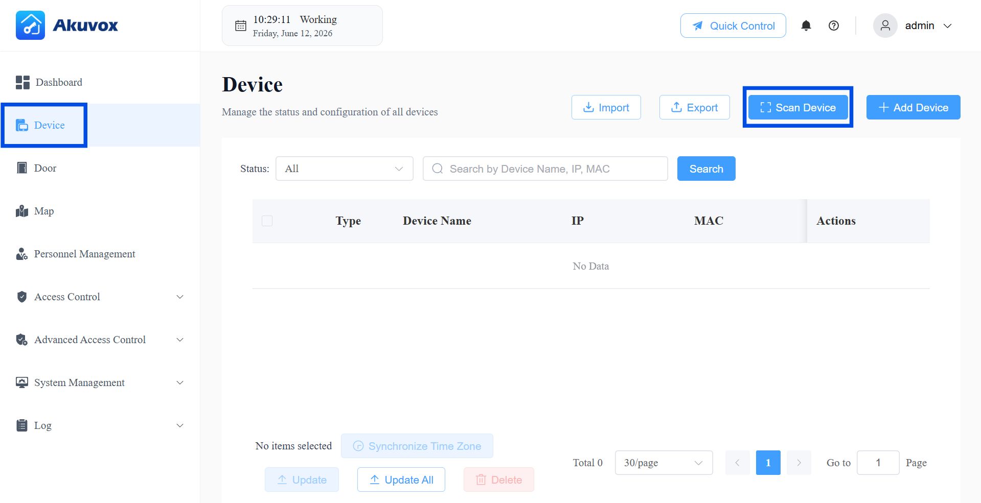
Devices on the same local network will display on the list.
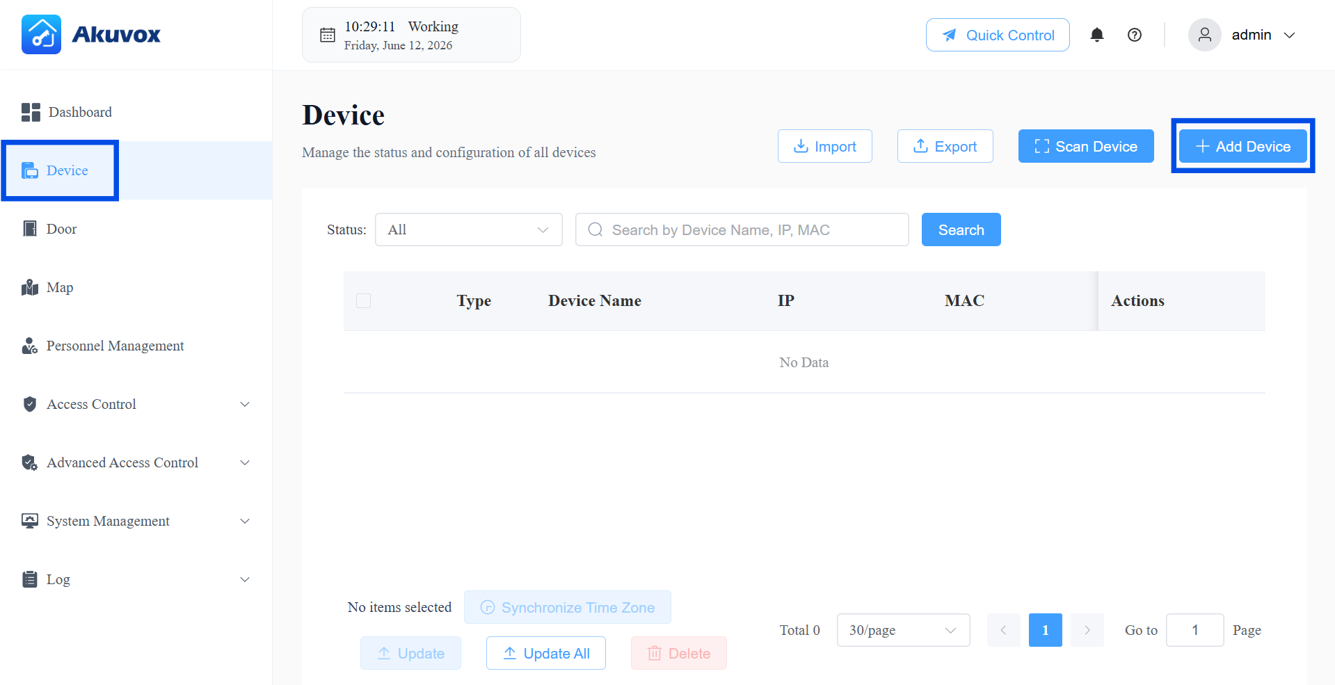
Add Manually
Click Device > + Add Device.
Enter the device’s information. See the item description in the chart below.
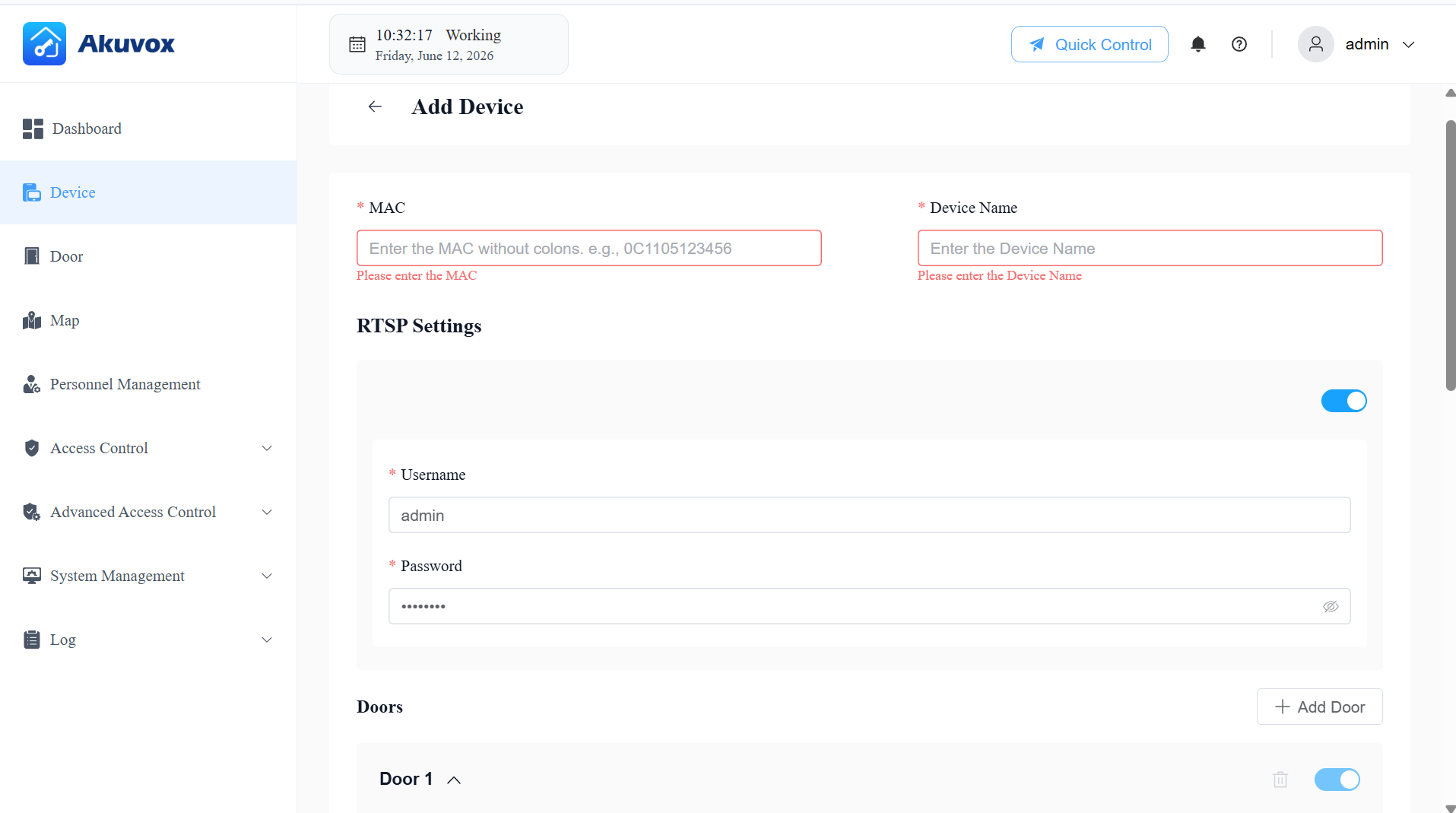
When adding a device, you'll also configure the door(s) it controls. A device can control one or more doors — click +Add Door to configure additional doors. Each door's configuration is grouped into three parts:
Entry/Exit Controls — how users trigger a door-opening action.
Lock and Sensing — how the system controls and detects the door's physical state.
Alarms and Status — additional alarm settings based on the door sensor configuration; these require the sensor to be configured first.
Item Name | Description |
|---|---|
MAC | The device’s unique MAC address. |
Device Name | The device name. |
RTSP Settings | Available for devices supporting RTSP. Enable or disable the RTSP function. When enabled, set the Username and Password.
Note: RTSP authentication is always enabled on Akuvox door phones. Therefore, ACMS Pro only delivers the RTSP feature switch, username, and password to the device. The authentication switch itself is not configurable. |
Door Name | The door name, e.g., front door. |
DTMF Code | The DTMF code for the door access. |
Controlled Relay | Specify the relay that is connected to the door lock. |
Entry Reader | The reader controls the entry door.
NOTE: When the controlled relay is selected Door(A095), select the reader from Reader 1~8 since A095 has 8 reader interfaces that can be connected for Wiegand or RS485 feature. |
Exit Reader | The reader controls the exit door.
NOTE: When the controlled relay is selected Door(A095), select the reader from Reader 1~8 since A095 has 8 reader interfaces that can be connected for Wiegand or RS485 feature. |
Exit Button | Input A ~ D: Select it when the input is connected to an exit button. Users can press it to open the door. NOTE: When the controlled relay is selected Door(A095), select from REX1~4 that corresponds to the label on the device. |
Door Sensor Connect To | Select the input port that is connected to a door sensor. It can be used to detect whether someone breaks in forcibly or if the door-opening time exceeds a limit.
|
Door Held Open Alarm | Available when Door Status is configured. This feature allows the device to sound an alarm when the door-opening time exceeds a certain limit. If enabled, set Door Opened Timeout beyond which the alarm will be triggered. |
Break-in Alarm | The feature allows the device to sound an alarm when the door is opened abnormally. |
Door Status Indicated By | Use the relay or the door sensor(connected to the device input) to indicate the door status. |
Add Door | Add doors when the device is connected to more than one lock. |
Add Devices in a Batch
Click Devices > Import.
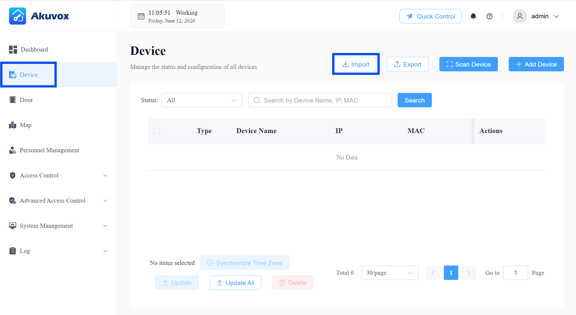
Click Download Import Template.
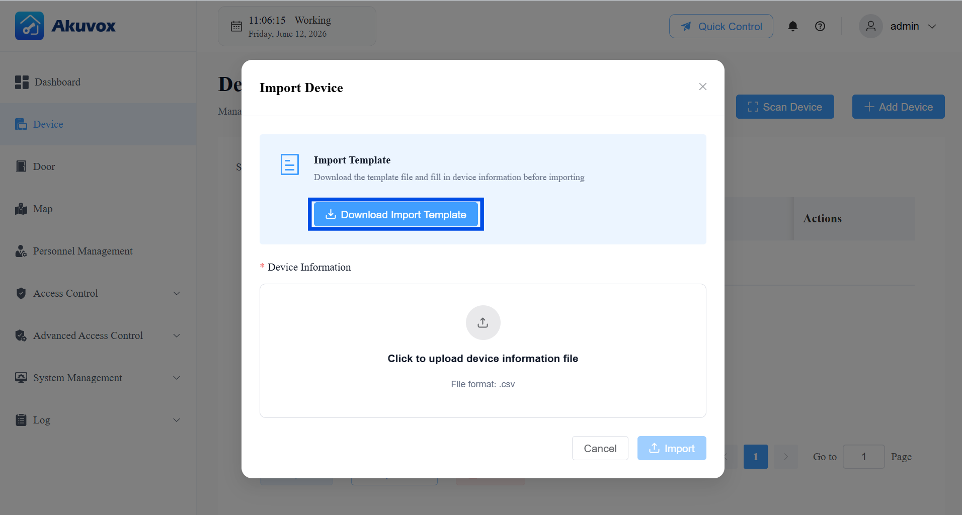
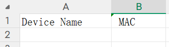
In the template, enter the device name and MAC address.
Click Import and upload your completed .csv file.
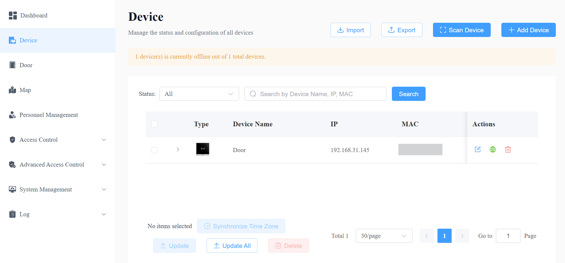
Edit/Delete Devices
On the Devices module,
Click
 to change the device’s settings. Please note that if you change the device’s MAC address, the related door logs, call histories, motion alerts, alarm records, and captures will be cleared.
Click
 to redirect to the device’s web interface.
Click
 to call the device.
Click
 to delete it.
Click
 to display the configured door.
Part 5: Door Management
Doors configured when adding/editing a device appear automatically in the Door module. You can manage doors using two complementary tools: Quick Control (immediate, manual actions) and Door Schedule (automated, time-based rules).
Access Control Priority Levels:
Quick Control: Highest priority. Control doors even if they are in the state preconfigured by the Door Schedule. For example, if a door is set to hold open from 8 AM to 12 PM daily, you can close the door at any time via quick control.
One-Time Runs: The second-highest priority. Only one schedule can be active per day, and one-time runs take precedence over Routine Schedules and Holidays. For instance, if a door is set to hold open for one-time runs on a holiday, users can open it during the holiday.
Holiday and Routine Schedule: These have the lowest priority and will only be effective if there are no active One Time Runs or Quick Control adjustments.
Door Quick Control
On the Doors module, you can view each door's status and location, and perform the following quick actions:
Unlock: Triggers a single momentary unlock — the door re-locks automatically after the device's configured open duration.
Hold Open: Sets the door to remain open for a selected duration. While it's open, click Restore at any time to return it to its default locked state early.
Lockdown On: While in lockdown, normal access methods (credentials, exit buttons, etc.) are disabled — only personnel with Lockdown Bypass permission can gain access. To exit lockdown, perform another Quick Control action and turn Lockdown Off.
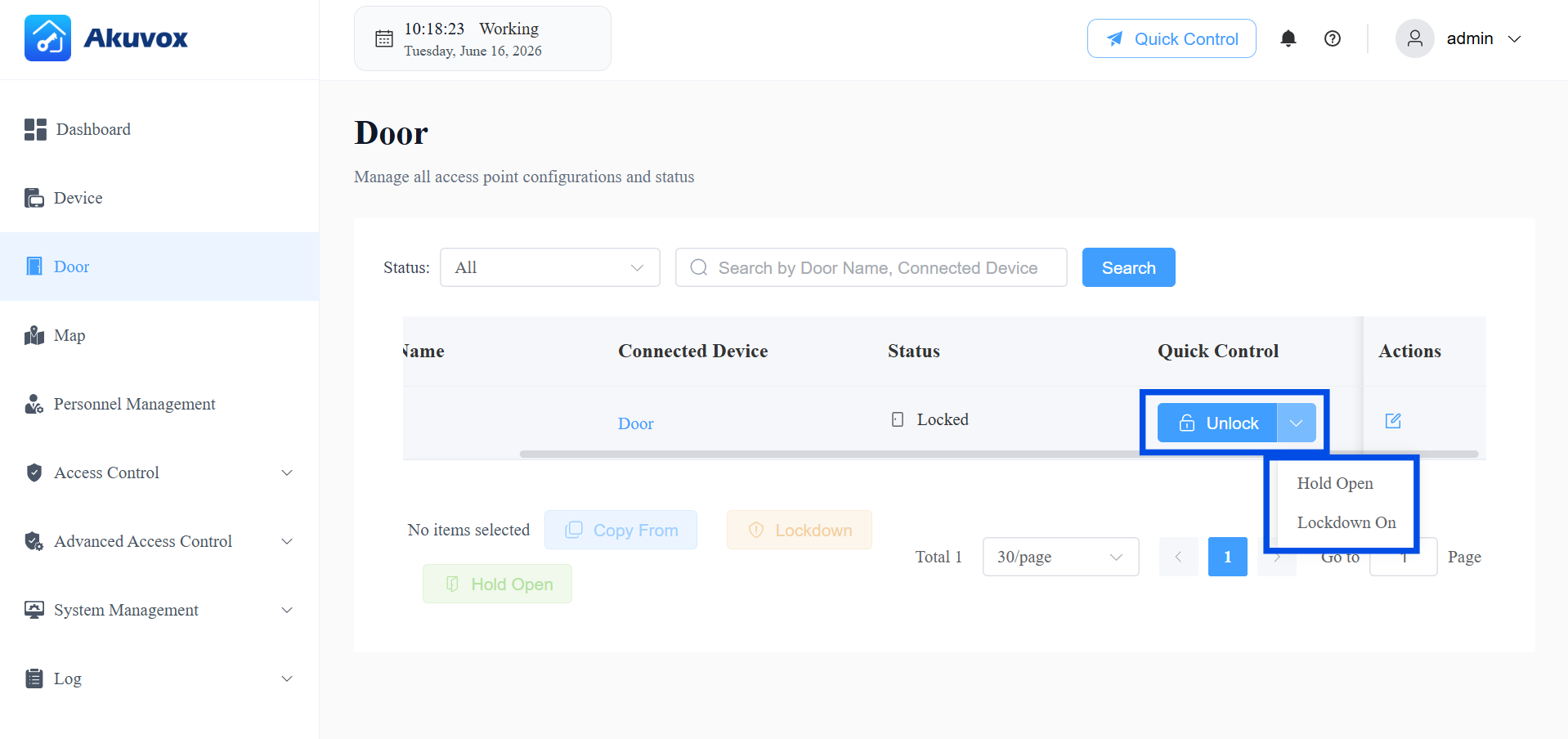
You can also control doors via the Quick Control tab at the top of the page.
Choose All Doors or Select Doors.
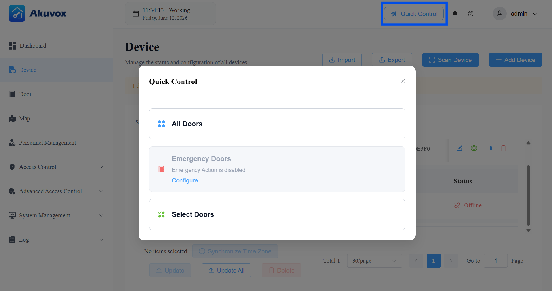
Select the desired action.
Door Schedule
A Door Schedule is a timetable that automatically changes a door to a preset state at specific times.
It supports two repeat modes:
Routine Schedules: The schedule repeats every week.
One-Time Runs: Set the daily or weekly schedule that repeats during a defined period.
Both support the same three door modes:
Hold Open: The door remains open during the scheduled time.
First Credential In: The door remains open during the scheduled time, starting after a user presents valid credentials for the first time.
Lockdown: The door remains locked during the scheduled time.
Common Configuration Steps
On the Door module, click
of the desired door.
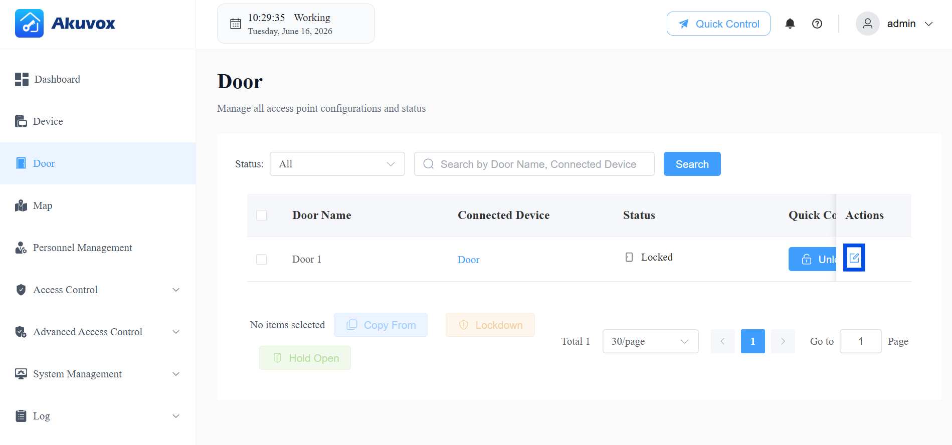
In the Door Schedule section, select Routine Schedule or One-Time Runs.
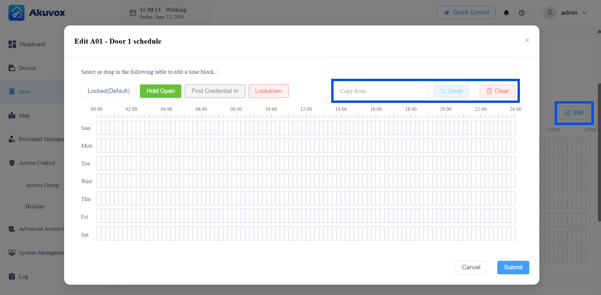
For the Routine Schedule, click Edit on the right.
For One-Time Runs, first click +Add and enter a Name, set the Effective Time (date range), and choose the Repeats mode (Daily or Weekly).
Select a door mode (Hold Open / First Credential In / Lockdown), then click and drag on the time grid to select a time block.
Use Copy from to copy a schedule from another configured door.
Use Undo to revert a change, or Clear to remove the current configuration.
Click a selected time block to fine-tune it:
Type: Change the door mode for this block.
Start Time / End Time: Set the exact times, or check All Day.
Allow Manual Termination: If enabled, users with "First Credential In Permission" can manually close the door while it's held open during this time block.
Copy to: Quickly duplicate this time block across the whole week, weekdays, or weekend.
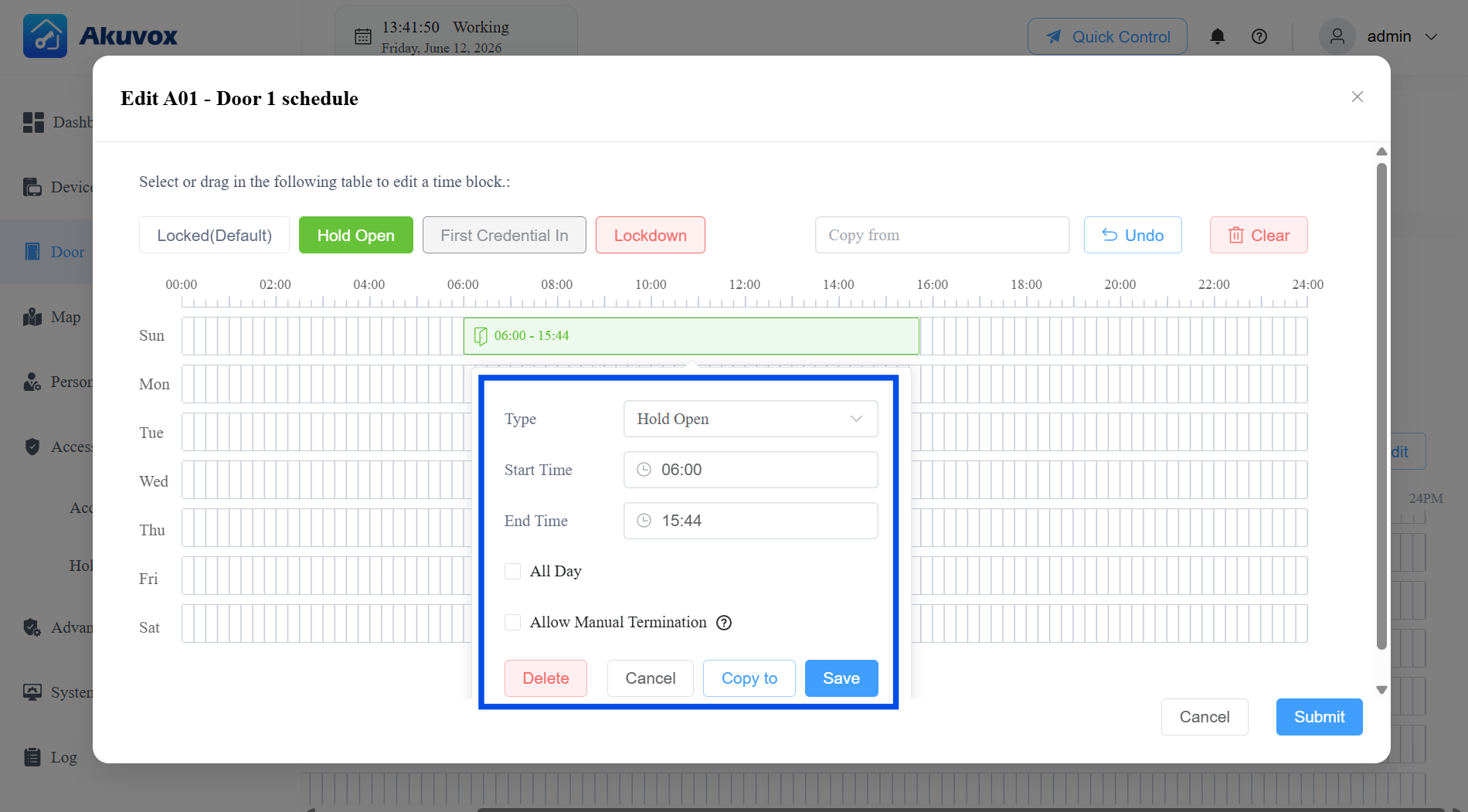
Click Save to save the time block, then Submit to save the entire schedule.
Part 6: Department Management
Departments and personnel work together with Access Groups to form the foundation of your access control structure. Before diving into the individual steps, here is how the three relate to each other:
A Department is a container for organizing personnel. You can assign one or more Access Groups directly to a department, and all personnel in that department will automatically inherit those access permissions.
A Personnel record stores an individual's identity information and credentials (PIN, RF card, Face ID, fingerprint). You can also assign Access Groups to individuals directly — individual assignments and department-level assignments stack together.
An Access Group defines the schedule (when) and the doors (where) a user is permitted to enter. See Part 7 for Access Group configuration.
Add a Department
Click Personnel Management > +New Department.
Enter the department name.
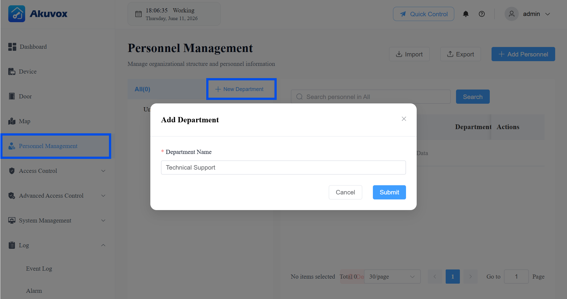
Click Submit.
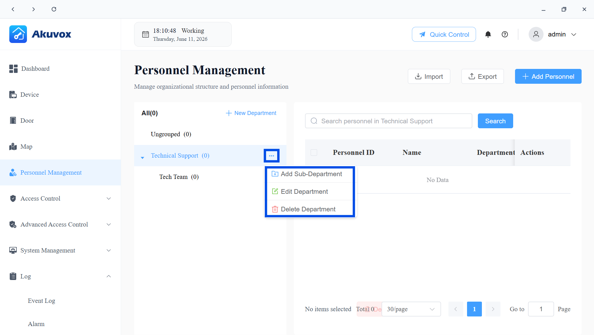
Edit/Delete a Department
Click the menu icon
 next to the target department.
Select the desired action.
Add Sub-Department: Creates a child department under the selected one, useful for multi-level organizational structures.
Edit Department: Opens the department editing page, where you can rename the department and assign Access Groups to it.
Delete Department: Removes the department. Personnel previously assigned to this department will become Ungrouped.
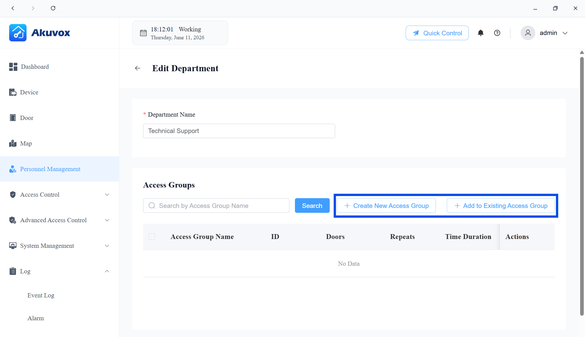
On the Department Editing page, you can apply access group(s) to the department.
Click Create New Access Group to build one from scratch, or Add to Existing Access Group to link an already-configured group. Once linked, all personnel in the department automatically gain the access permissions defined by that group.
Part 7: Personnel Management
You can add personnel one by one or import in a batch.
Add Personnel One by One
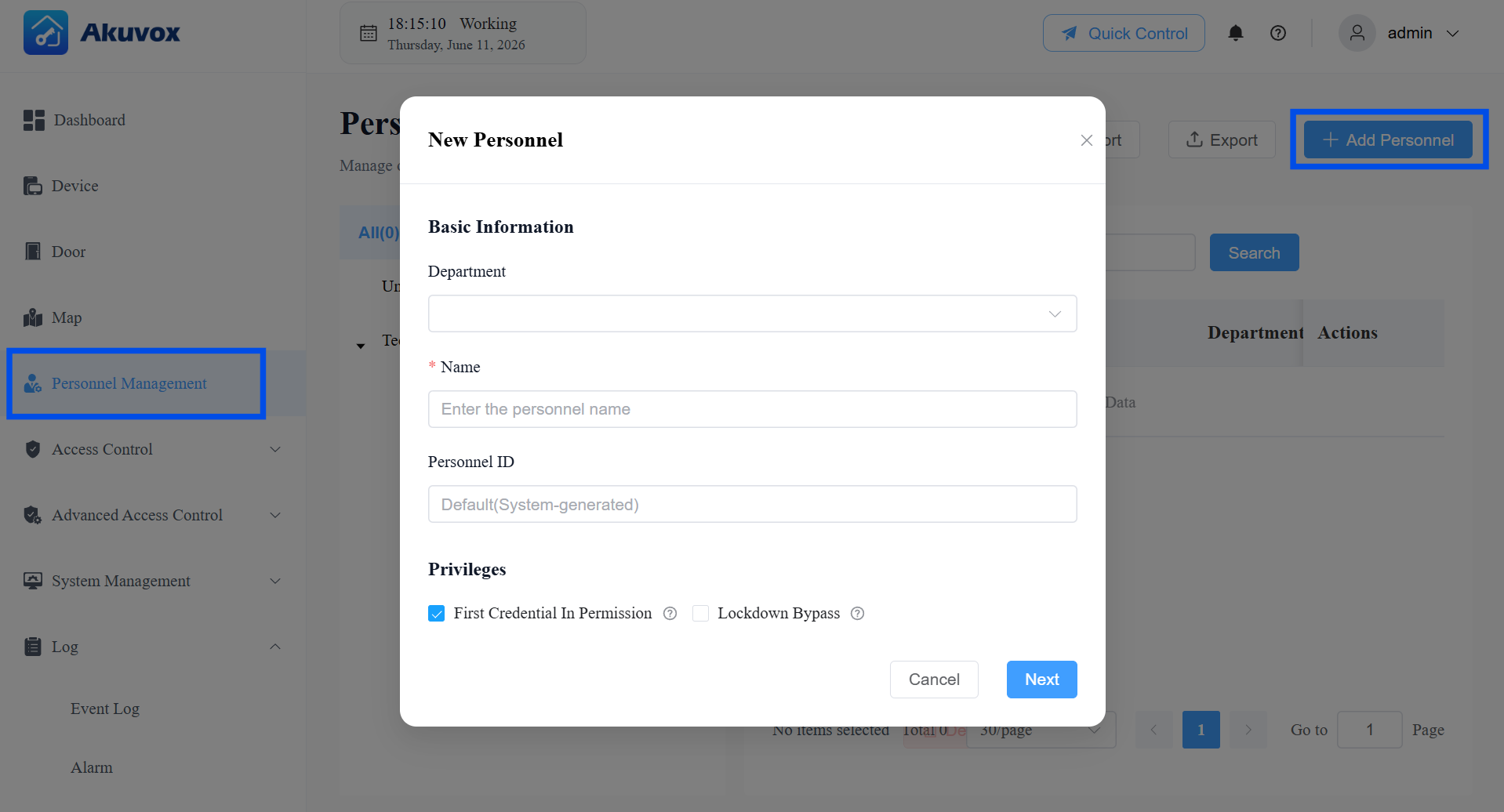
Click Personnel Management > +New Personnel.
Enter the user information and set up permissions. See item description in the chart below.
Item Name | Description |
|---|---|
Department | Select the personnel’s department from the dropdown. |
Name | The personnel name. |
Personnel ID | Leave empty to have the system generate one automatically, or enter a custom ID of up to 63 characters. |
Privileges |
|
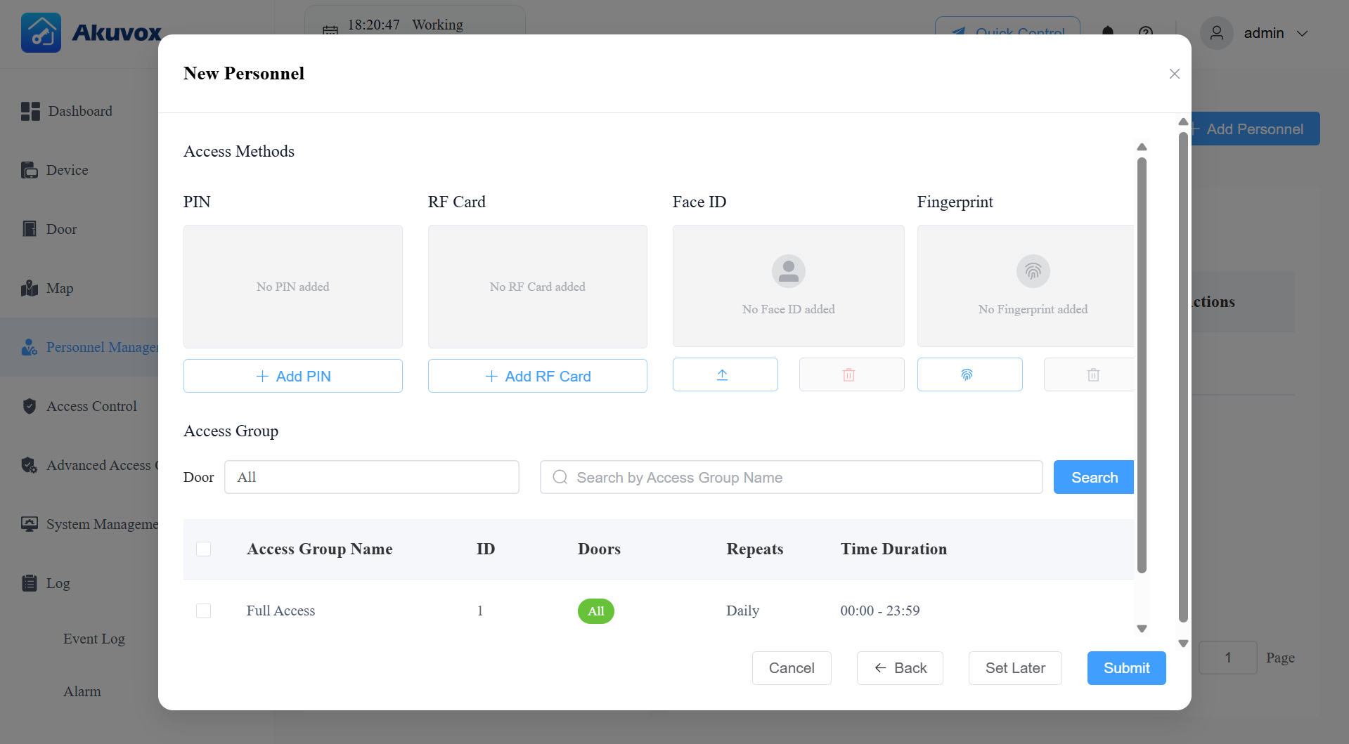
Click Next to set up the personnel’s access credentials. See item description in the chart below.
You can click Set Later to save the user information only.
Item Name | Description |
|---|---|
PIN | 2~8-digit PIN code without starting with “9”. |
RF Card | 1~16 characters that can contain 0~9 and A~F. |
Face ID | Upload the user’s front-facing picture for facial recognition unlock. |
Fingerprint | Enroll the fingerprint with the Akuvox fingerprint reader ACR-CID13. |
Access Group | Select the access group that defines when the user can open doors. |
Click Submit.
Add Personnel in a Batch
Use batch import when you need to set up a large number of personnel at once.
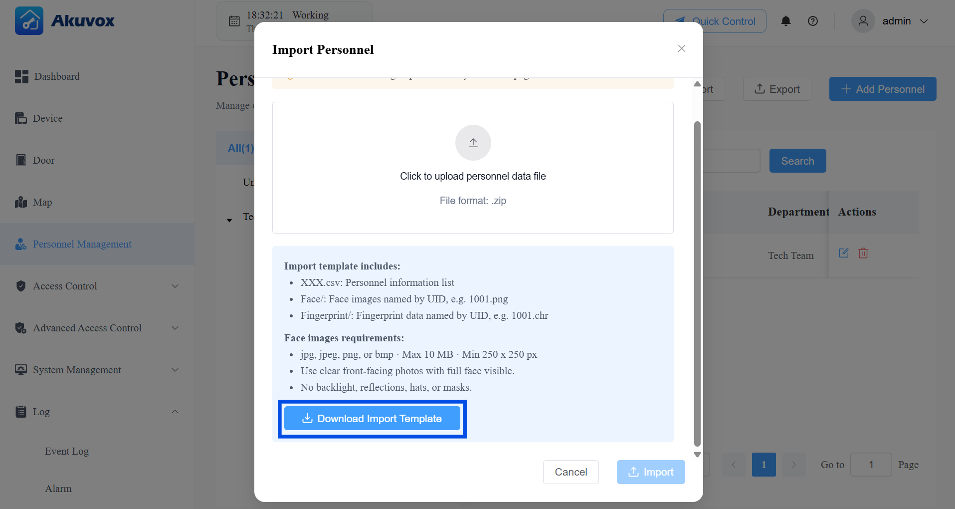
Click Personnel Management > Import.
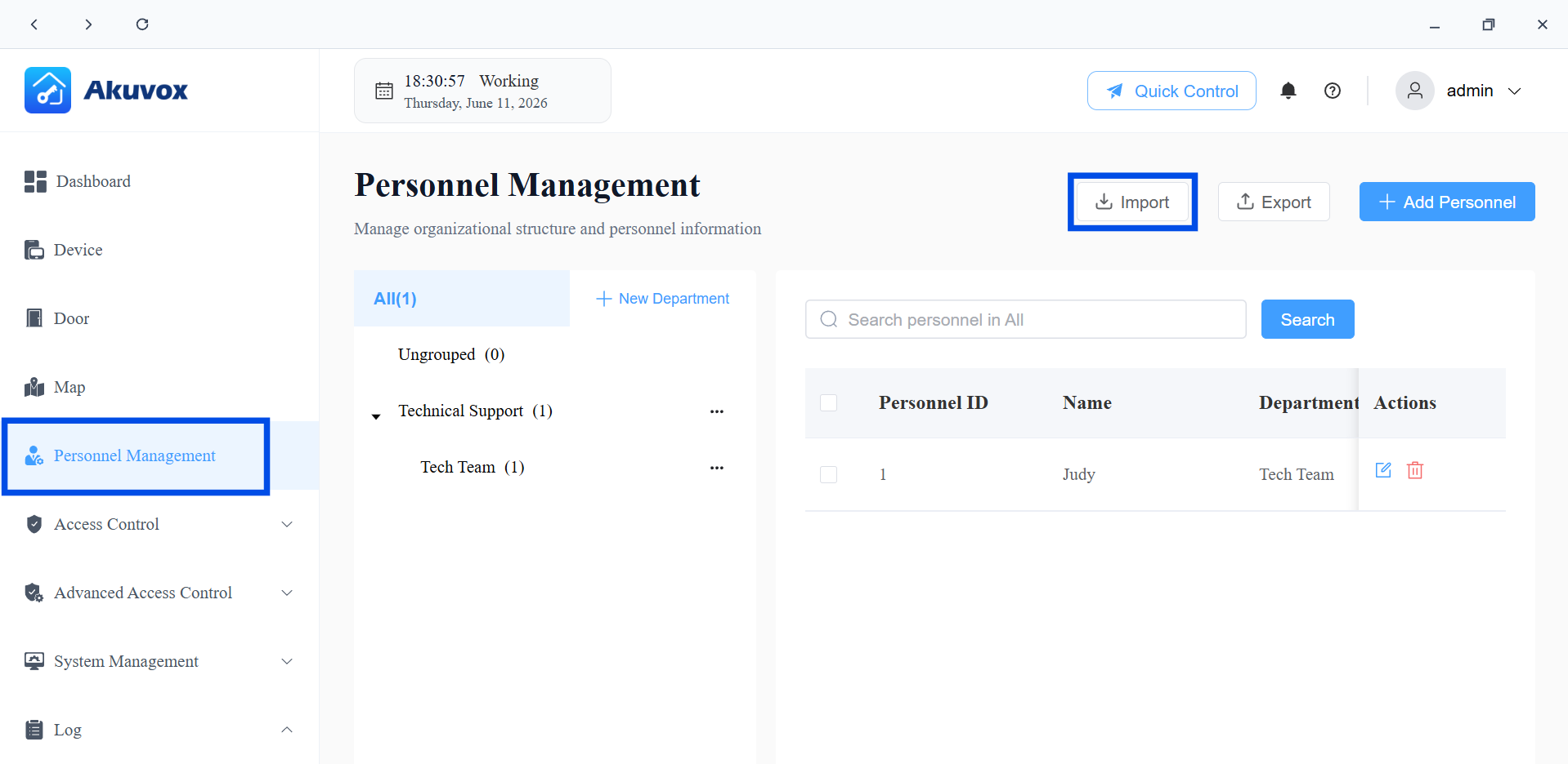
Click Download Import Template. The template package contains:
personnel template.csv — the personnel information spreadsheet.
face/ folder — place facial photos here, named Personnel ID.png.
fingerprint/ folder — place fingerprint templates here, named Personnel ID.chr.
Edit the Personnel Template. Read the instruction file Readme before filling in information. See the full field reference below.

Item Name | Description |
|---|---|
Department | The department name. Must match an existing department in the system exactly. |
Name | The personnel name. Required. |
ID | Personnel ID, maximum 63 characters. The system uses this to match facial photos (Personnel ID.png) and fingerprint templates (Personnel ID.chr) to the correct person. |
RF Card | 1~16 characters that can contain 0~9 and A~F. |
PIN | 2~8-digit PIN code without starting with “9”. |
PIN Enabled | Set whether to enable the PIN access method. 0: Disabled 1: Enabled |
RF Card Enabled | Set whether to enable the RF card access method. 0: Disabled 1: Enabled |
Face ID Enabled | Set whether to enable the face recognition access method. 0: Disabled 1: Enabled |
Fingerprint Enabled | Set whether to enable the fingerprint access method. 0: Disabled 1: Enabled |
Access Group ID | Enter the ID of the access group that defines when the user can open doors. |
First Credential In | Set whether the user can use their credentials to keep the door open. 0: Disabled 1: Enabled |
Lockdown Bypass | Set whether the user can open the door if it is locked down. 0: Disabled 1: Enabled |
Place any facial photos and fingerprint templates into the corresponding folders, following the naming requirements.
Compress the entire folder structure into a .zip file.
Click Import and upload the .zip file.
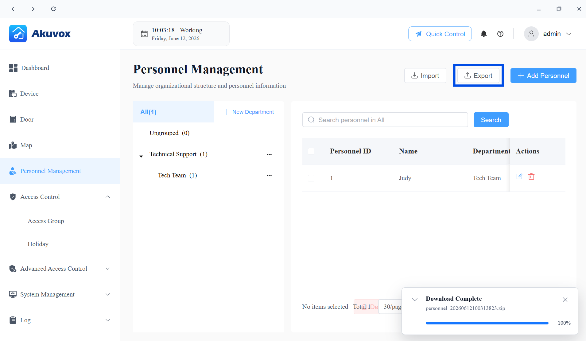
Export Personnel Data
Click Export on the Personnel Management page to download a .zip file containing all current personnel records, facial photos, and fingerprint templates.
The exported file uses the same structure as the import template. Common uses include:
Backing up personnel data before a system migration.
Editing a bulk export in the .csv file and re-importing it to apply mass changes.
Reusing personnel data as a starting template for a new project.
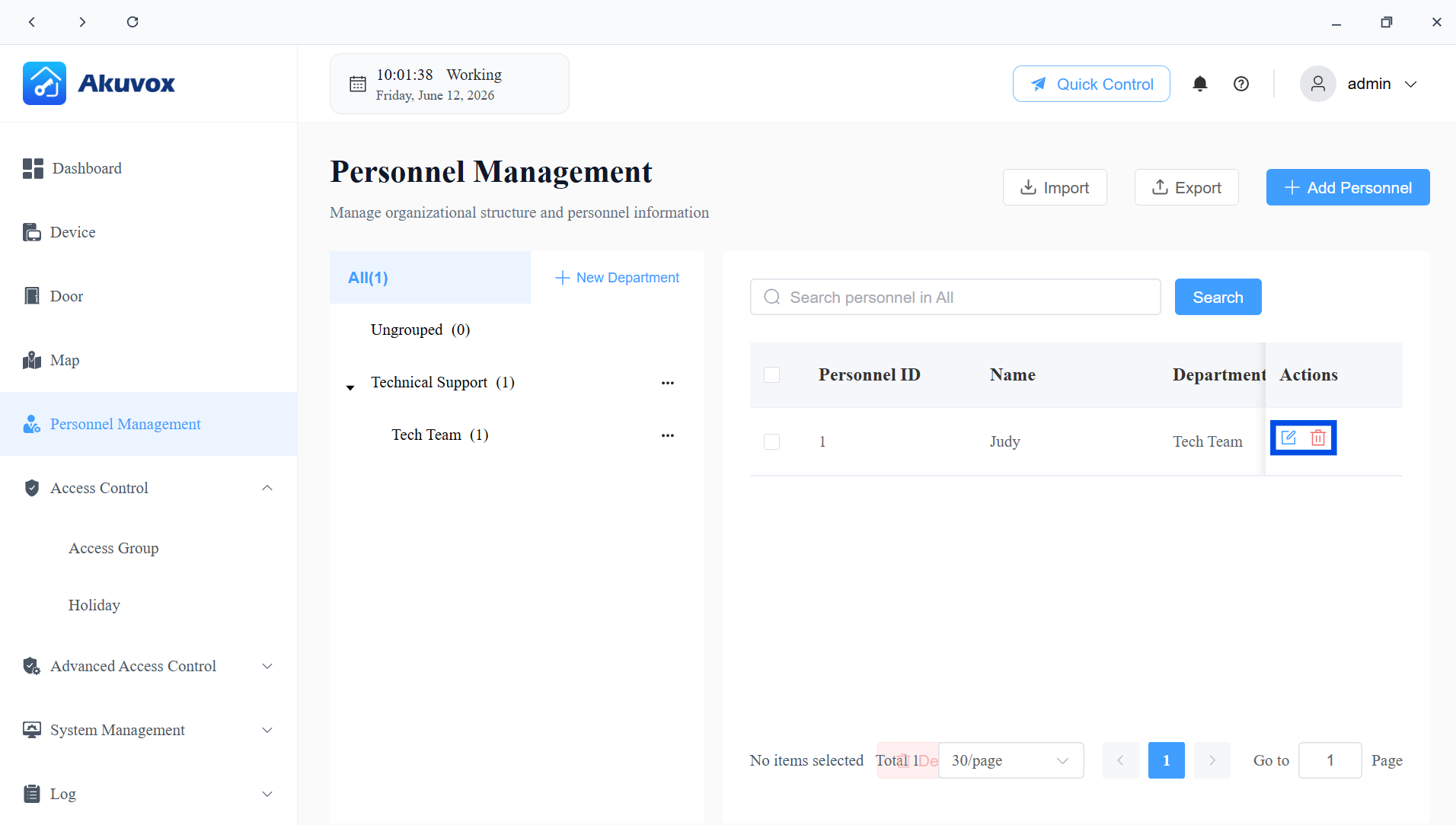
Edit/Delete Personnel
On the Personnel Management page:
Click
 to view and update a person's basic information, credentials, and access group assignments.
Click
 to remove the personnel.
Part 8: Access Group Management
An Access Group is a reusable access permission template. It defines:
When users can open doors (the access schedule).
Which doors they can open.
Who the group applies to (all personnel, a specific department, or specific individuals).
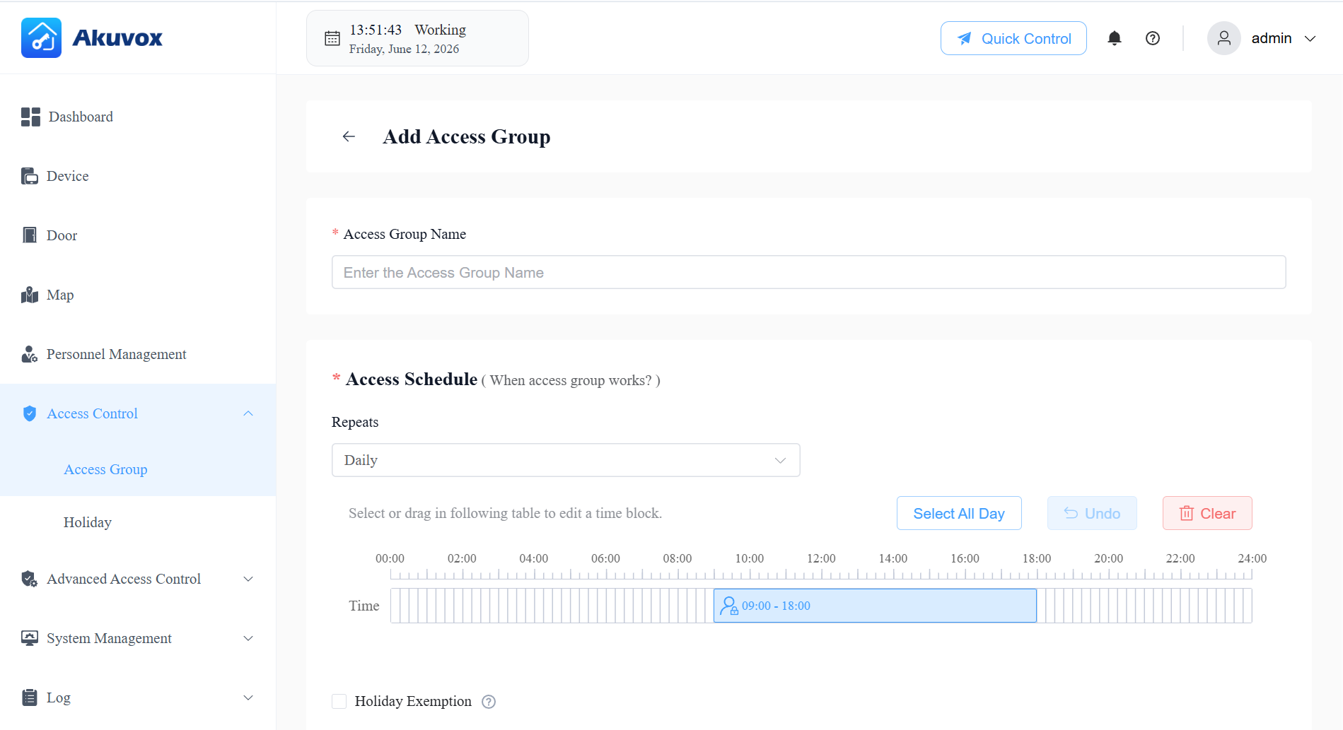
Create an Access Group
Click Access Control > Access Group > +Add.
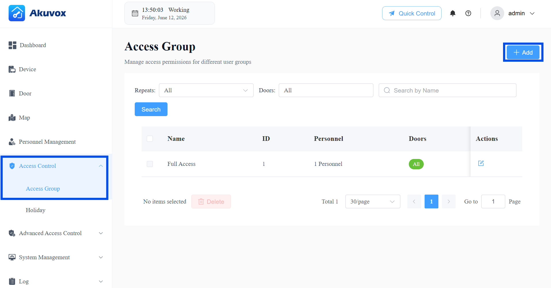
Name the group.
Select the repeat mode: Daily, Weekly, or Never.
Enable/disable Holiday Exemption. This decides whether the users in the access group can open doors during holiday schedules.
Select users who are authorized to open the door.
If Custom is selected, click +Add in the Department section to select a department. All users in the department will be granted permission to open the door.
Click +Add in the Personnel section to select a specific user.
Select the door(s) to be opened. If Custom is selected, choose the door from the dropdown.
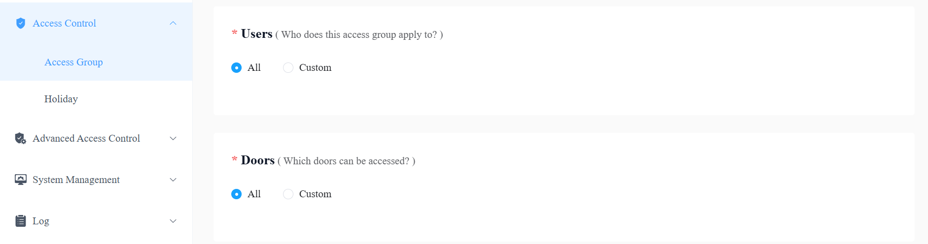
Submit the setting.
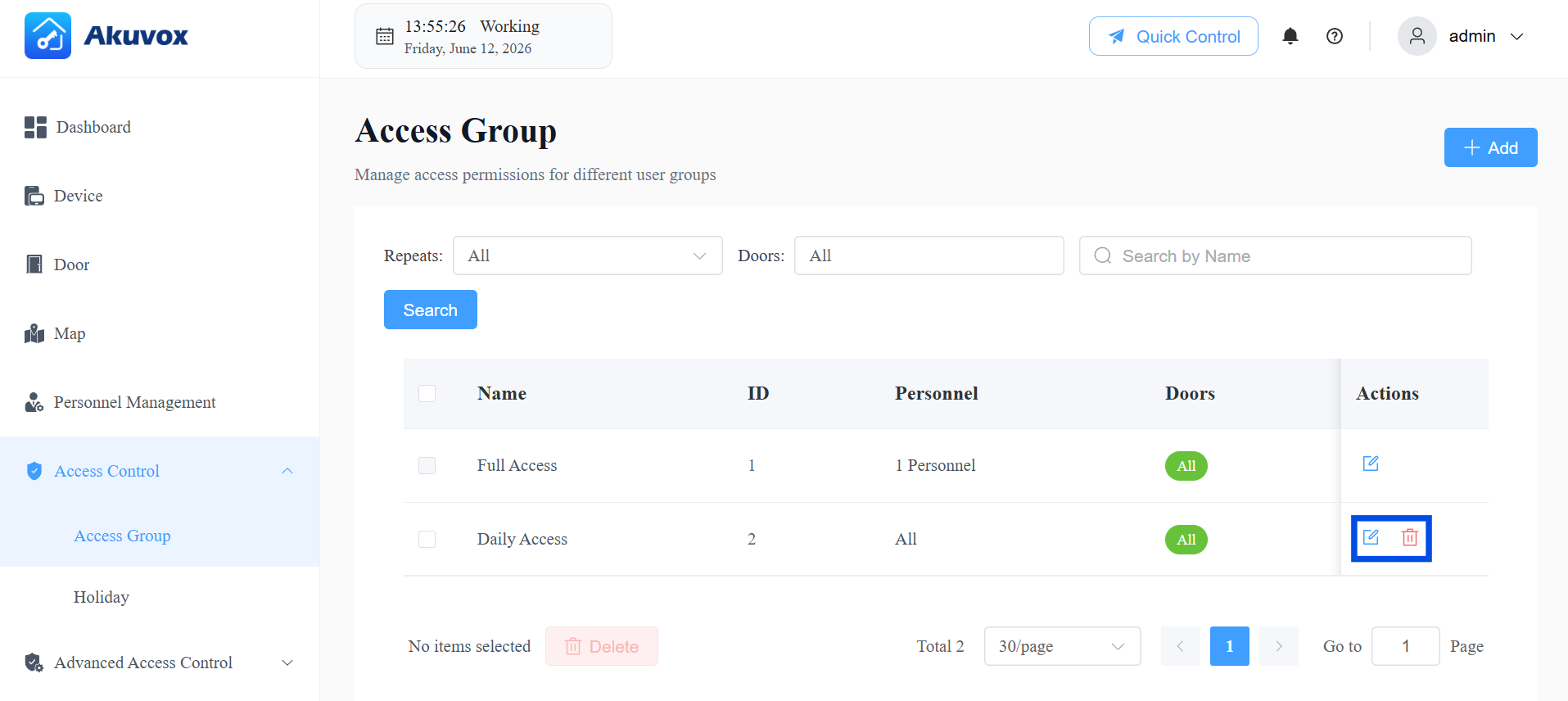
Edit/Delete Access Groups
The system-generated default group cannot be edited or deleted.
Click Access Control > Access Group.
Click
to modify its settings; click  to delete it.
Holiday Access Control
Holiday Access Control lets you define periods when personnel cannot open doors, in order to tighten security during holidays or closed periods.
When a day falls within a configured Holiday, all Access Groups without Holiday Exemption enabled will not grant access during that period.
Click Access Control > Holiday > +Add.
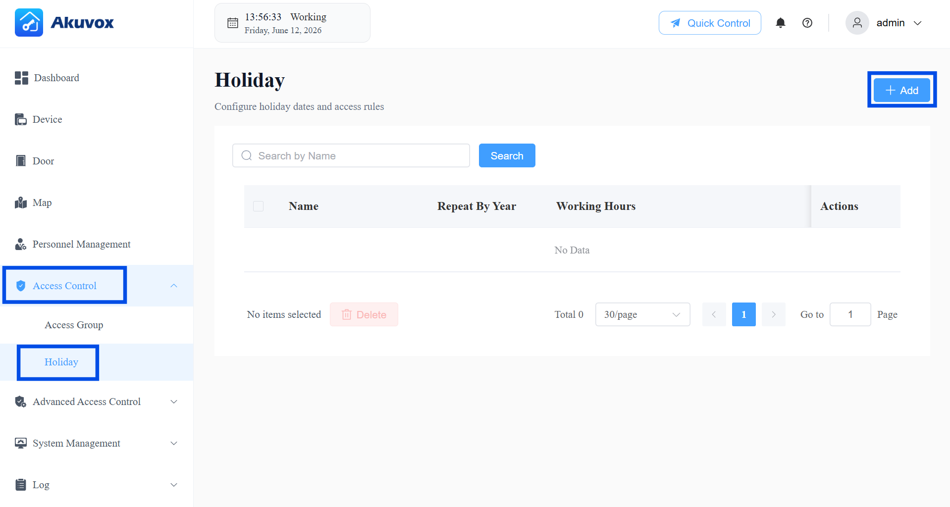
Enter the holiday name.
[Optional] Enable Working Hours to allow authorized personnel to open doors. When enabled, specify the time.
[Optional] Enable Repeat by Year to repeat the schedule every year.
Select the year and day(s) of the holiday schedule.
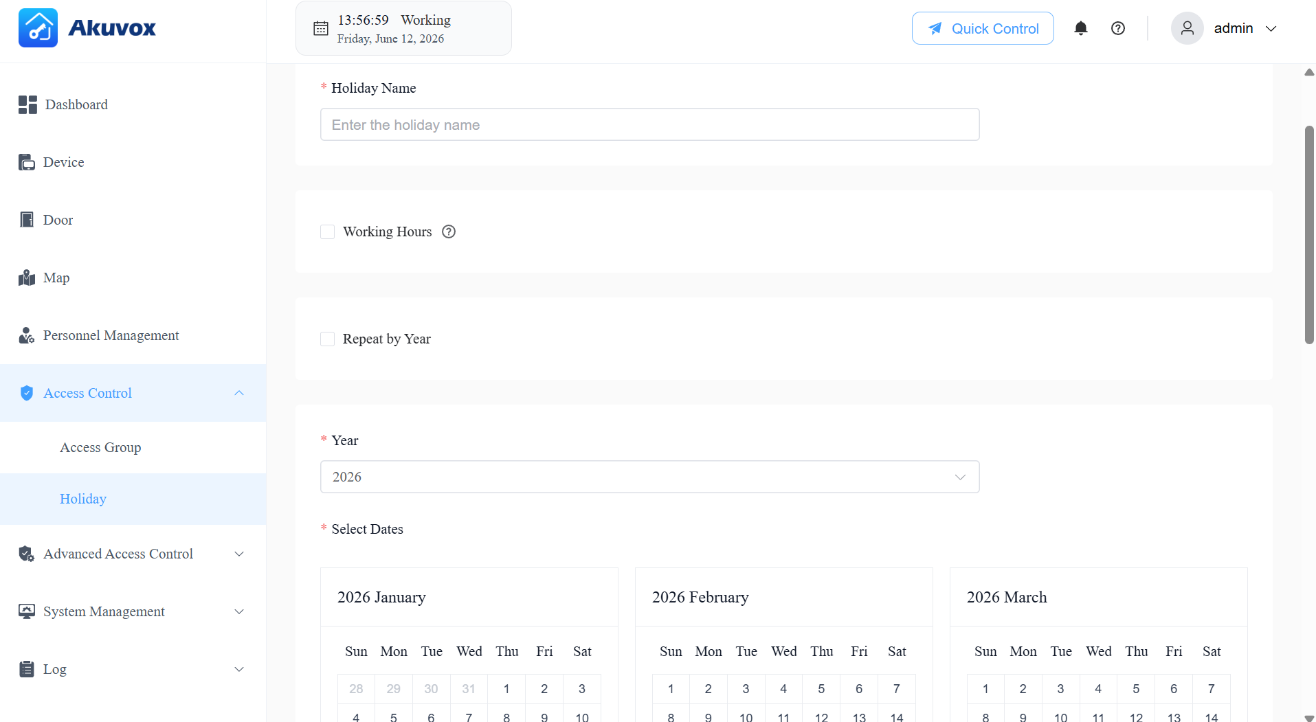
Submit the setting.
Edit or Delete a Holiday
On the Holiday page, click to update an existing holiday schedule, or to remove it.
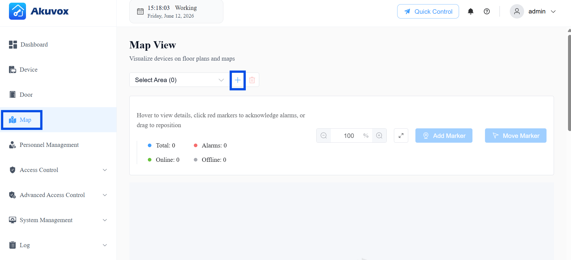
Part 9: Map Management
The Map module provides a visual floor plan interface, letting you see all your doors and their real-time status on a map. This is especially useful for managing large sites with multiple floors or zones.
Add an Area
Click Map >
 .
.
Enter the area name.
Upload an image for the area.
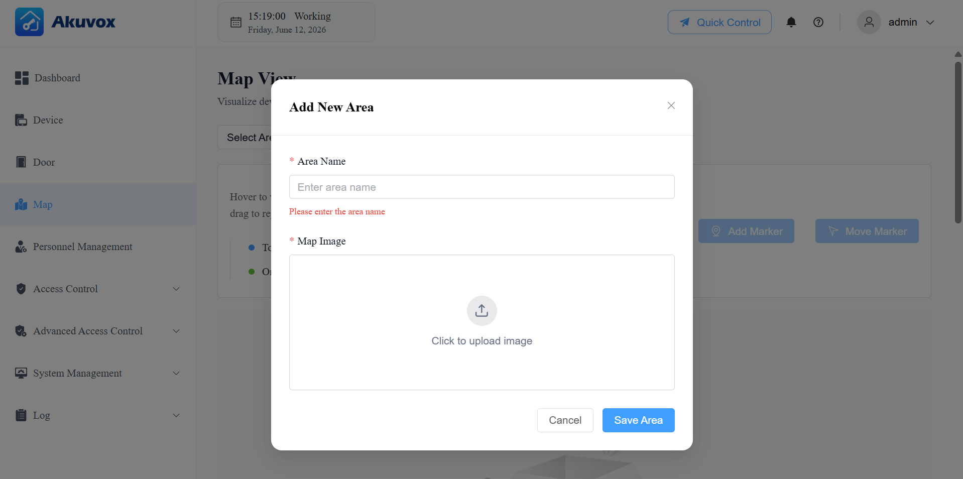
Click Save Area.
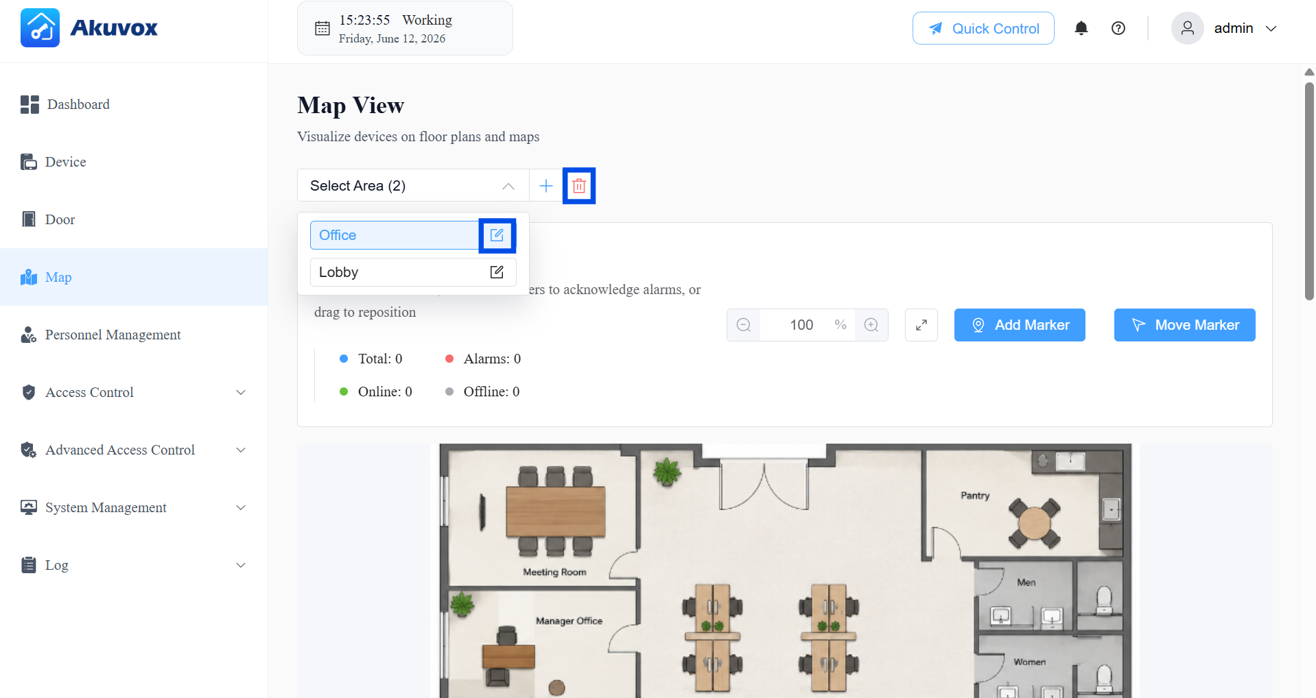
Edit/Delete an Area
Select the target area, and click to modify its settings; click to delete it.
Add Marker to an Area
Markers link physical doors to locations on the floor plan, allowing you to see and control them visually.
Click Add Marker.
Select the door location on the map.
Select the door to link to that location.
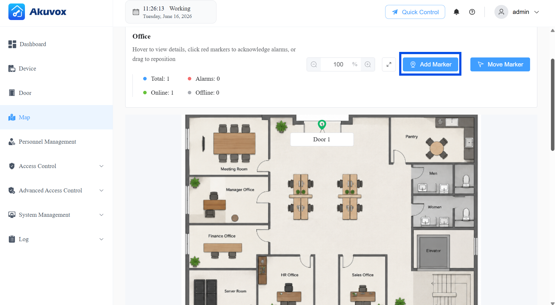
After adding the marker, click on it to edit, view the door details, and perform quick control.
Marker color meanings:
Gray: The door is offline.
Green: The door is online and in a normal state.
Red: The door has triggered an alarm (Emergency Alarm, Door Opened Timeout, Tamper Alarm, or Break-in Alarm).
Note
Alarm-based markers (Door Opened Timeout, Tamper Alarm, and Break-in Alarm) require the corresponding alarm features to be configured in the device's Door settings first. When one of these alarms is triggered on a red marker, you can click Disarm to clear it.
Emergency Alarms cannot be cleared via Disarm and require manual administrator acknowledgment.
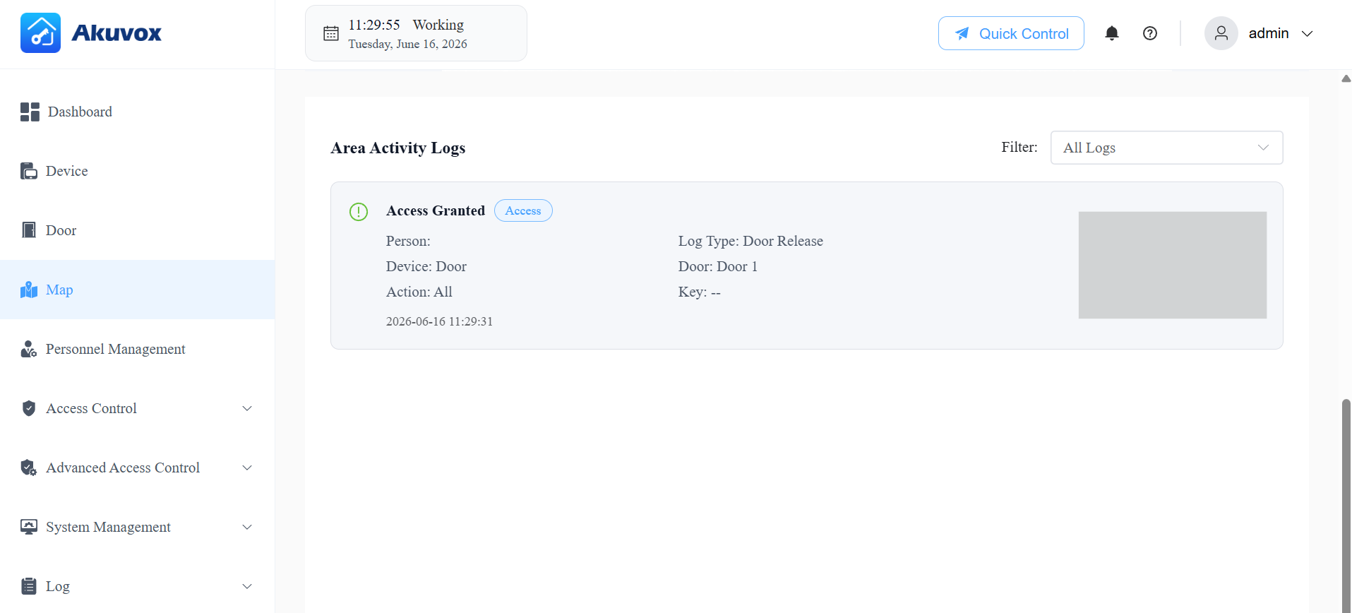
Area Activity Logs
The map view also displays access logs and alarm logs for the selected area. These reflect the same events visible in the Log module. For Emergency Alarms specifically, the alarm must be reviewed and actioned at the system level — it cannot be cleared by clicking Disarm on the map.
Part 10: Advanced Access Control
Interlock
Interlock prevents multiple linked doors from being open at the same time, strengthening security in areas such as airlocked vestibules or secure corridors.
How it works: When any door in an interlock group is open, all other doors in the same group are locked and cannot be opened until that door closes. If someone attempts to open a second door while the first is still open, the attempt is denied and logged as an Interlock Violation in the Access Log.
Click Advanced Access Control > Interlock > +Add.
Enter the Interlock Group Name.
Select the door(s) that use the rule(at least 2 doors required).
Toggle the Status switch to enable or disable the rule.
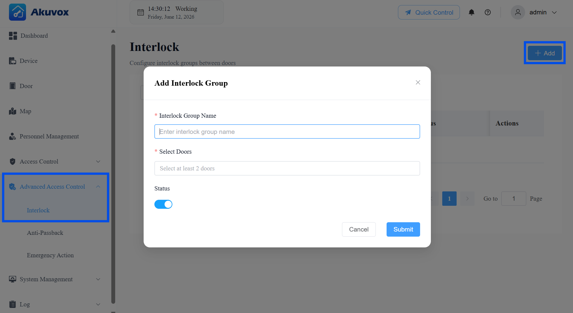
Click Submit.
Anti-Passback
Anti-Passback ensures that a credential follows a proper entry-exit sequence. After a user enters through an entry door, they must exit through an exit door before the credential can be used to enter again.
For example, if a user enters the office with their card, the card cannot be used for another entry until the user exits the office.
Click Advanced Access Control > Anti-Passback > +Add.
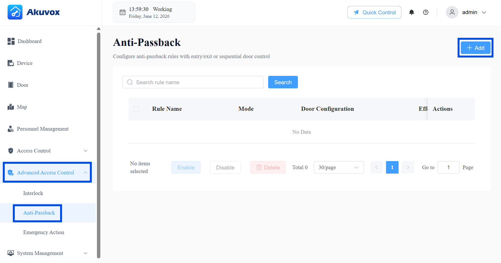
Enter the rule name.
Select the Anti-Passback Mode.
Entry/Exit Mode: Users must alternate between entry and exit doors — simplest setup, suitable for single-zone access.
Sequential Mode: Users must pass through doors in a specific order (e.g., 1 → 2 → 3) with no backtracking — use for multi-zone or multi-checkpoint layouts.
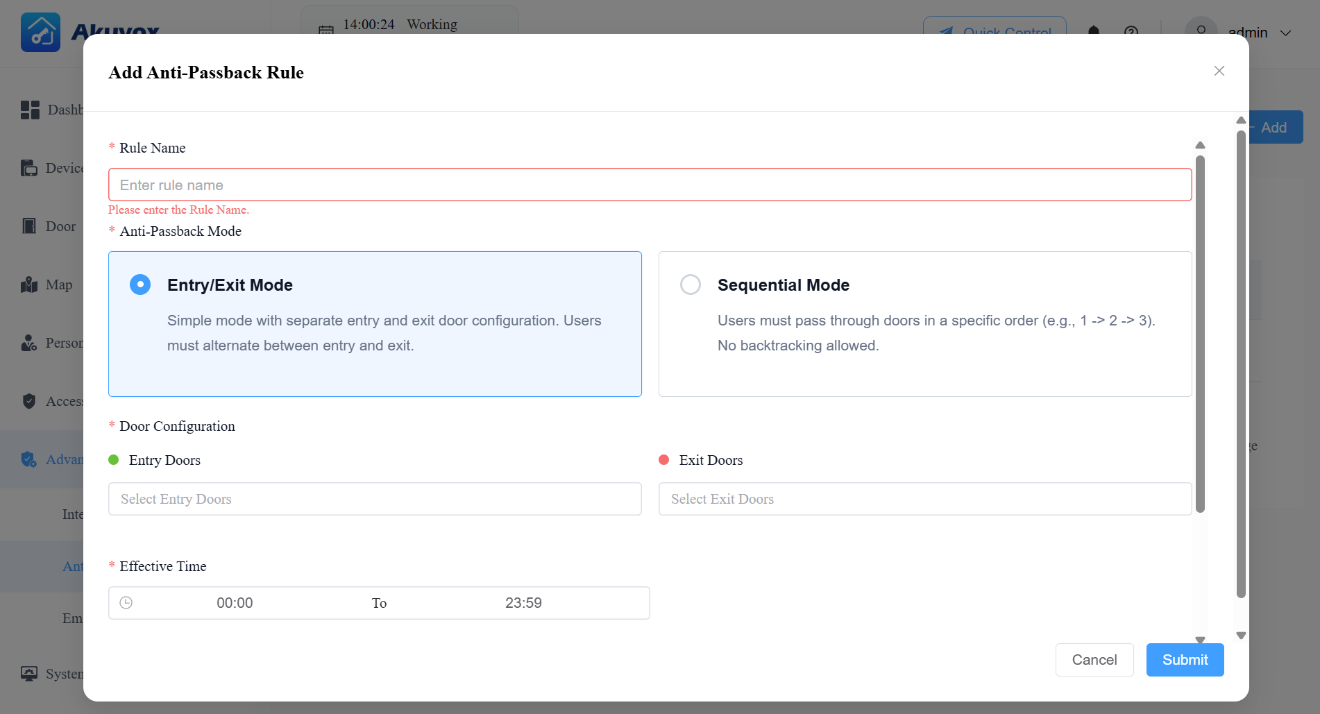
Door Configuration — based on the mode selected:
If Entry/Exit Mode:
Entry Doors: Select the door(s) that count as entry points.
Exit Doors: Select the door(s) that count as exit points.
The system will require a user to exit through an Exit door before they can enter again.
If Sequential Mode:
Available Doors: Select the doors that should be part of the sequence.
Sequential Order: Selected doors automatically appear in this list. Use the ↓ / ↑ arrows to arrange them into the exact order users must pass through (e.g., Door 1 → Door 2 → Door 3). Use
 to remove a door from the sequence.
Set the Effective Time during which the rule is active.
[Optional]Enable Allow Consecutive Access to allow a user to pass through the same type of door (e.g., two consecutive entries) without it being treated as a violation. Suitable for environments where users may occasionally re-enter without exiting first.
Set the Violation Lock Duration (minutes): The time a user's credentials will be locked out after triggering an anti-passback violation (e.g., attempting to re-enter without properly exiting first).
Toggle the Status switch to enable or disable the rule.
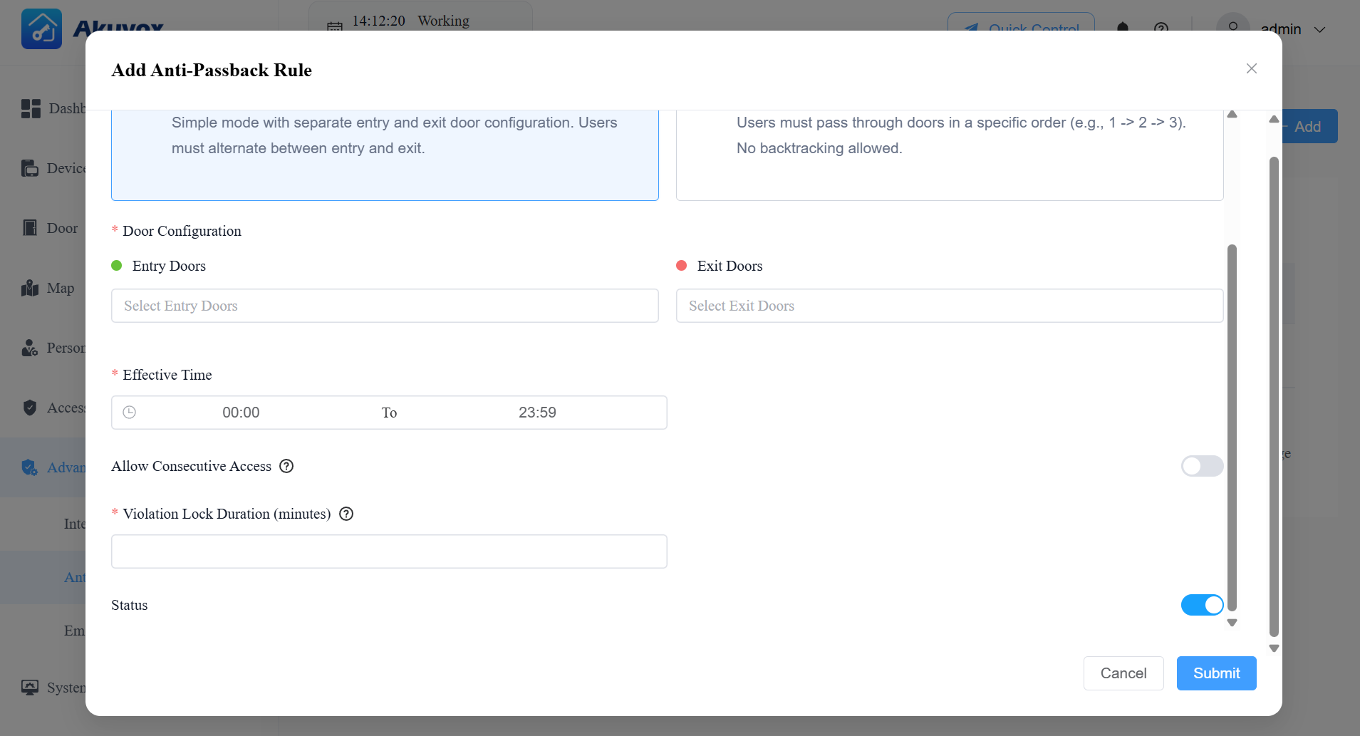
Click Submit.
After creating the anti-passback rule, you can check the current occupancy and blocked people.
People Inside: Display the number of personnel entering the area, only effective when the anti-passback feature is enabled.
Blocklist: Display the number of personnel and couriers who are denied access in the area. It is only effective when the anti-passback feature is enabled.
Emergency Action
Emergency Action lets you make all doors open or close automatically when a fire alarm or emergency alarm is triggered, or manually at any time by an administrator.
Example: In a fire emergency, the system can automatically unlock all exits as soon as an alarm is triggered on any door phone in the building, enabling rapid evacuation.
Click Advanced Access Control > Emergency Action. Or, click Quick Control at the top > Configure.
Enable Unlock Emergency Door Group When Emergency Alarm Triggered.
Under Emergency Door Group, select All Doors or choose specific doors to be unlocked during an emergency.
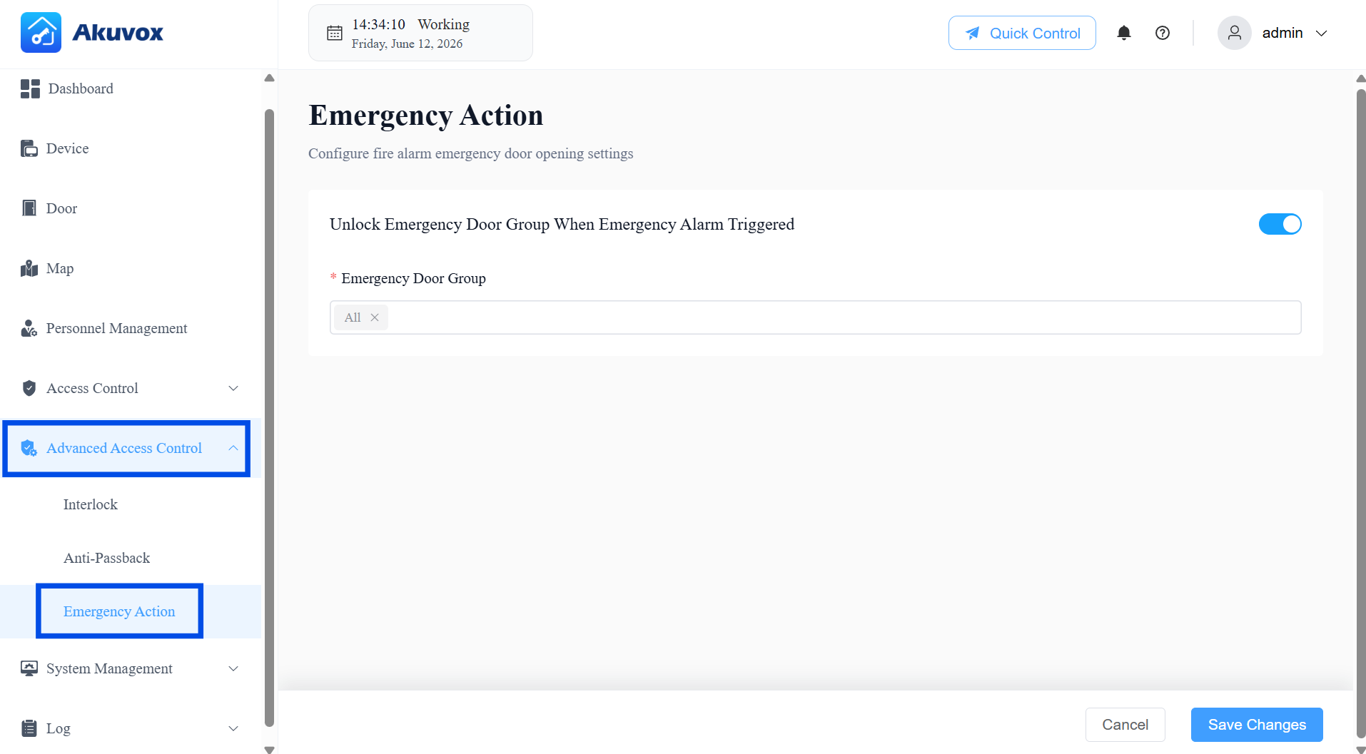
Click Save Changes.
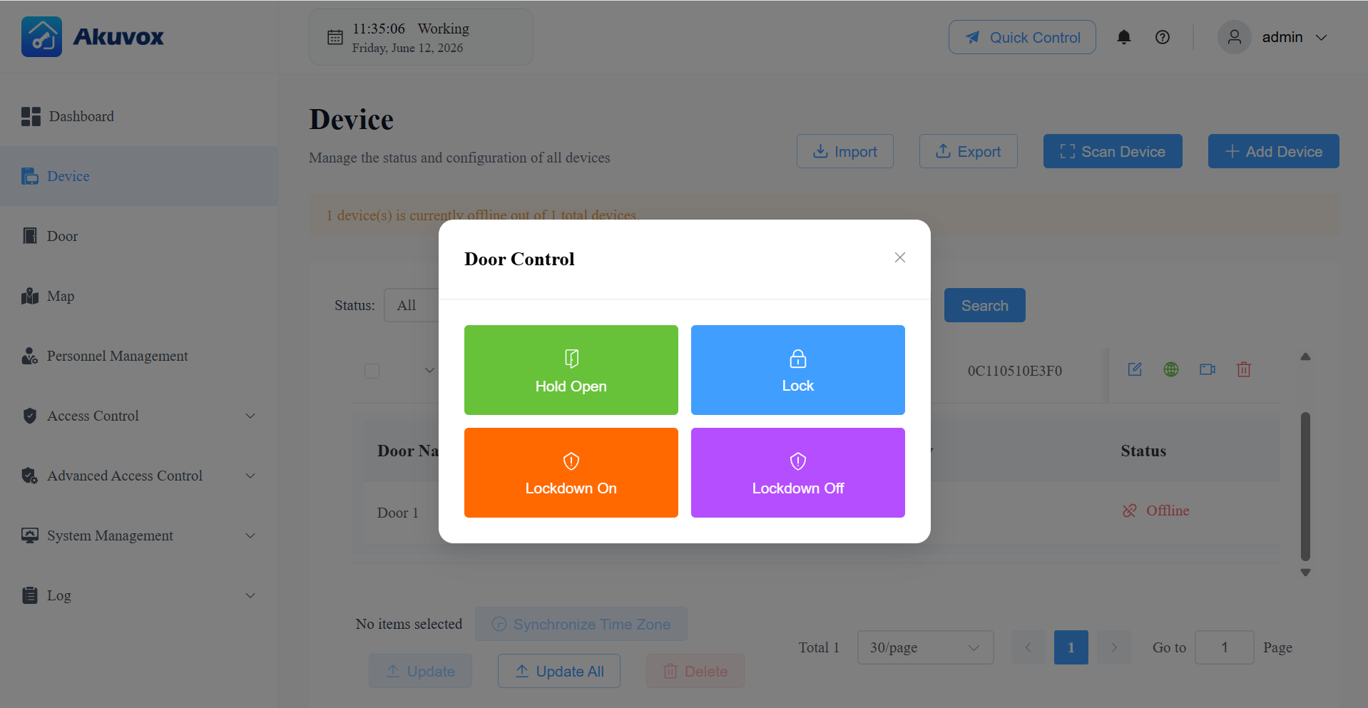
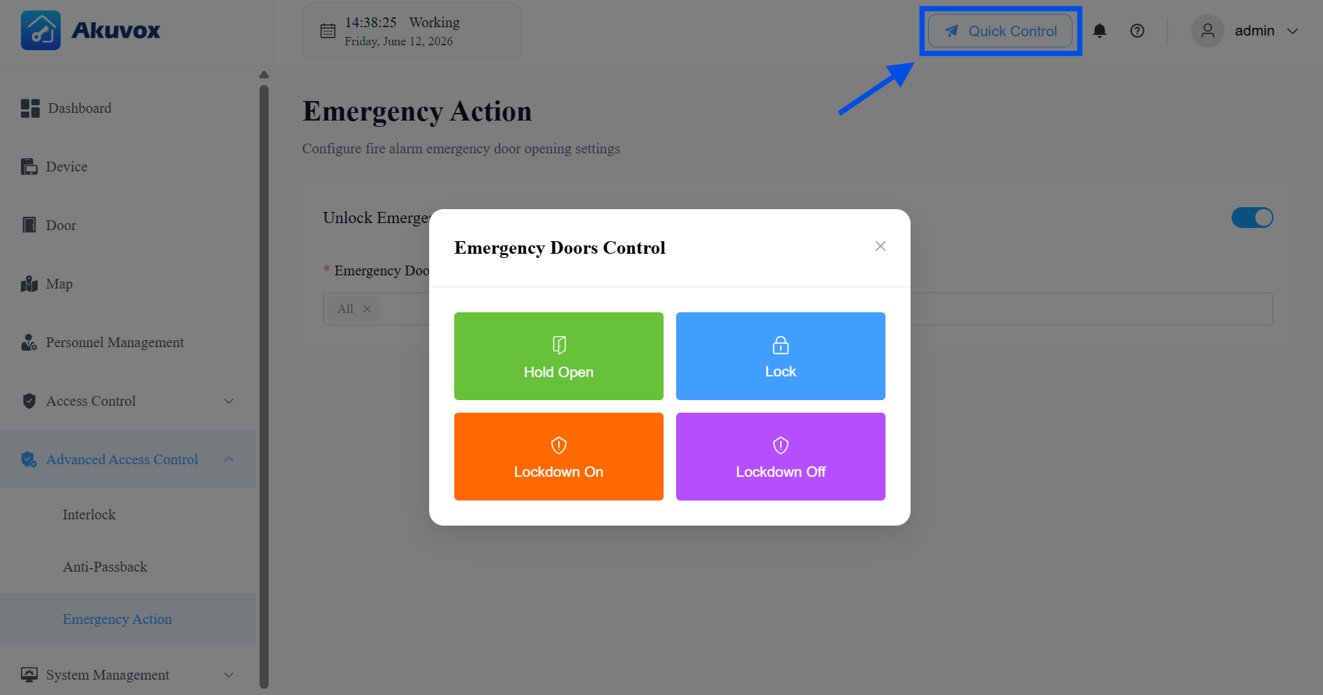
Trigger Emergency Actions:
Automatic: When a device in the Emergency Door Group triggers an emergency alarm, the system unlocks the configured doors automatically. This event is recorded in Log > Alarm > Emergency Alarm.
Manual: At any time, an administrator can click Quick Control > Emergency Doors and select Hold Open, Lock, Lockdown On, or Lockdown Off to manually control the emergency door group.
Note
Before using Emergency Action with ACMS Pro, you must first enable the feature on the device's web interface.
See Set up Door Phones section in the Set up Emergency Action article for instructions.
Part 11: Logs
You can check various logs in the Log module.
Export any log by clicking Export Logs in the upper-right corner of the relevant page.
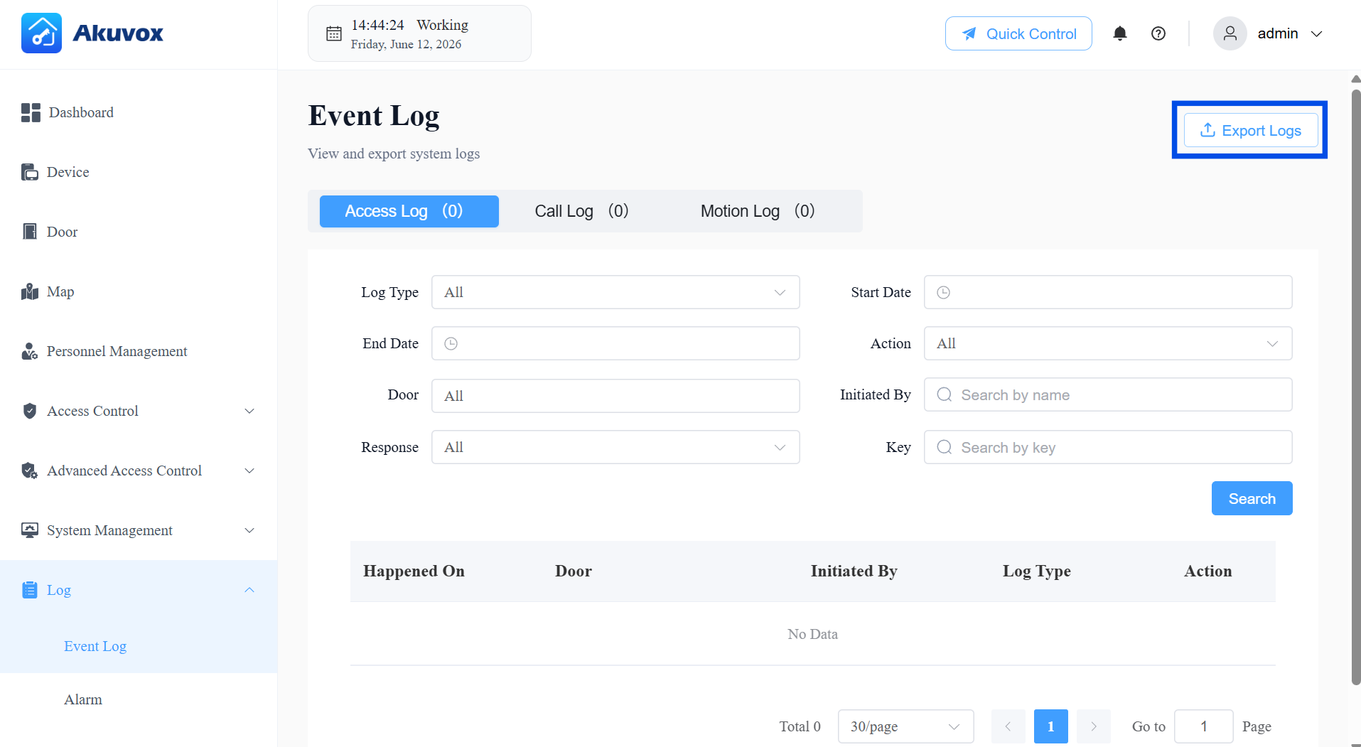
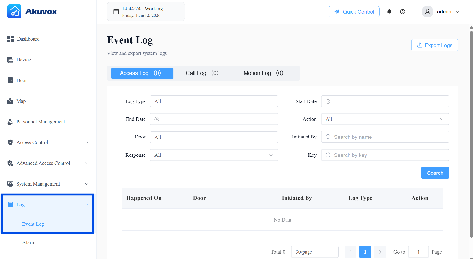
Access Log
Go to Log > Event Log > Access Log.
The Access Log displays all door-related activity records. Narrow your log check with filters for the targeted search. It has the following types:
Entry: Valid entry recorded under Anti-Passback rules.
Exit: Valid exit recorded under Anti-Passback rules.
Entry Violation: Anti-Passback violation — user attempted to enter again without a valid exit in between.
Exit Violation: Anti-Passback violation — user attempted to exit again without a valid entry in between.
Sequence-In: Valid access through the first door in a Sequential Mode configuration.
Sequence-Through: Valid access through a middle door in a Sequential Mode configuration.
Sequence-Out: Valid access through the last door in a Sequential Mode configuration.
Sequence Violation: Anti-Passback violation — door accessed out of the configured sequence.
Interlock Violation: Access denied because another door in the same interlock group is currently open.
Door Release: Access event not subject to Anti-Passback rules (includes general failed attempts).
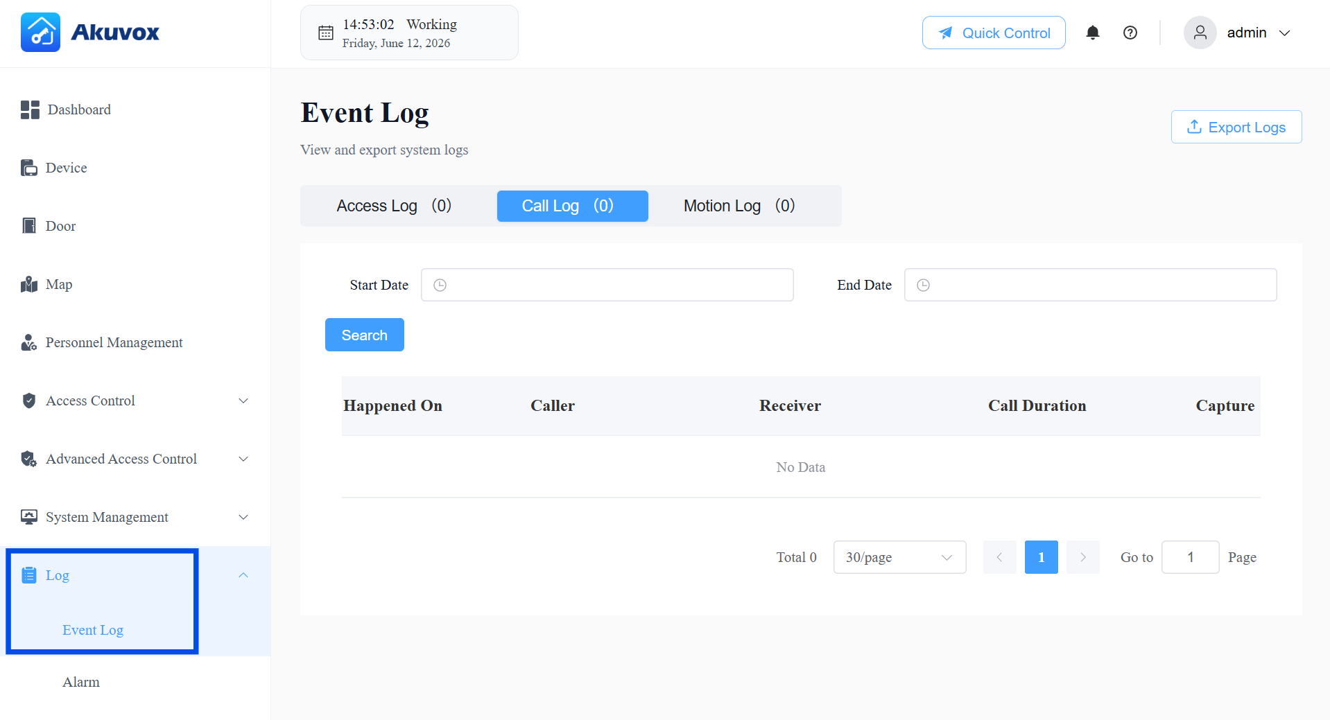
Call Logs
Go to Log > Event Log > Call Log.
Check all SIP calls made and received via the devices — including the time, caller, receiver, and call duration. Filter by date range or search by caller/receiver name to find specific records.
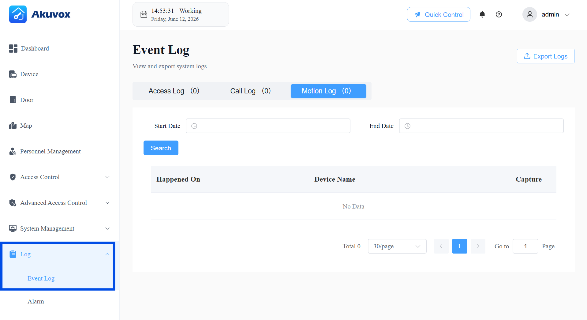
Motion Log
Go to Log > Event Log > Motion Log.
Check captured images triggered by motion detection on devices that support this feature. Filter by date range to review specific periods.
Note
Motion detection must be enabled on the device itself. Please refer to the article Configure Motion Detection.
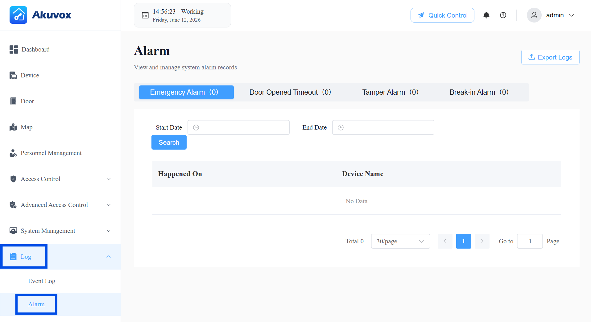
Part 12: Alarm Records
Go to Log > Alarm to review the following alarm types. Export any alarm log by clicking Export Logs in the upper-right corner.
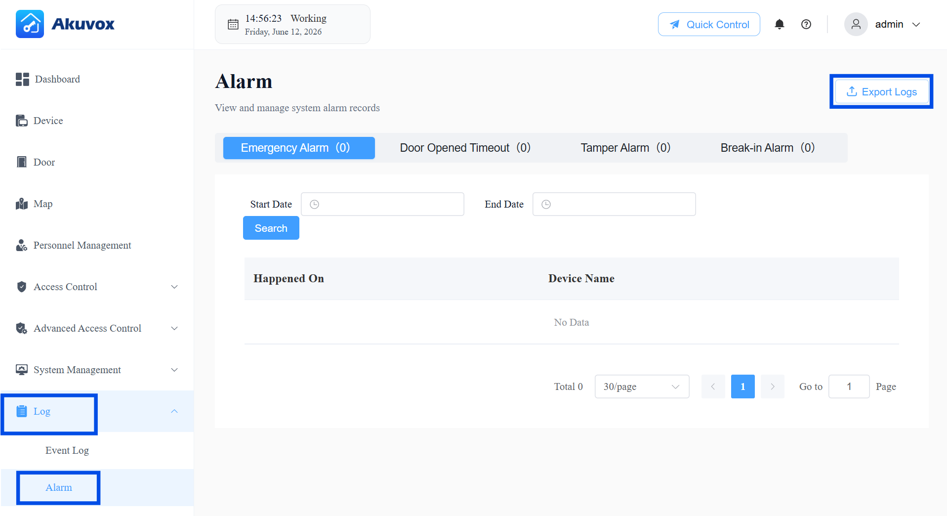
Emergency Alarm
Go to Log > Alarm > Emergency Alarm.
The emergency alarm is recorded when the emergency unlock occurs.
Narrow the search by entering a specific time.
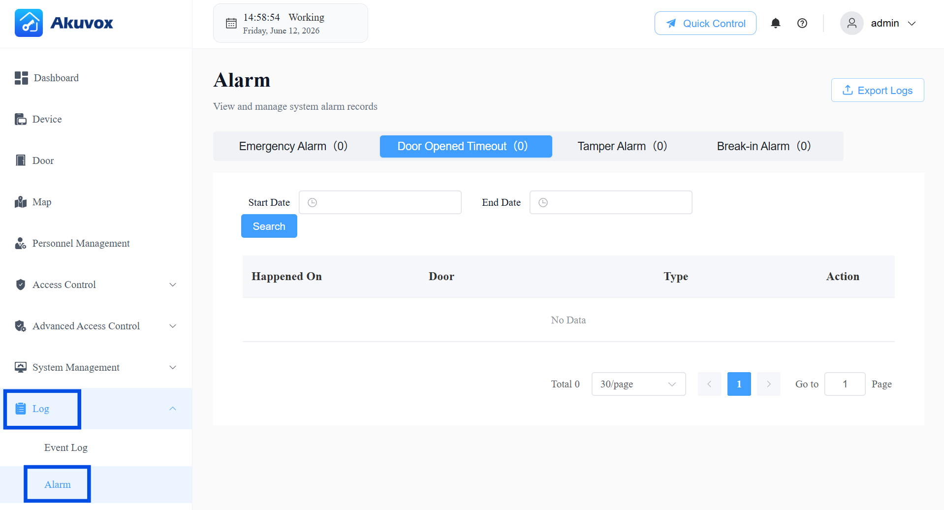
Door Opened Timeout Logs
Go to Log > Alarm > Door Opened Timeout.
When the door-opening time exceeds a certain limit, the alarm will be triggered and recorded.
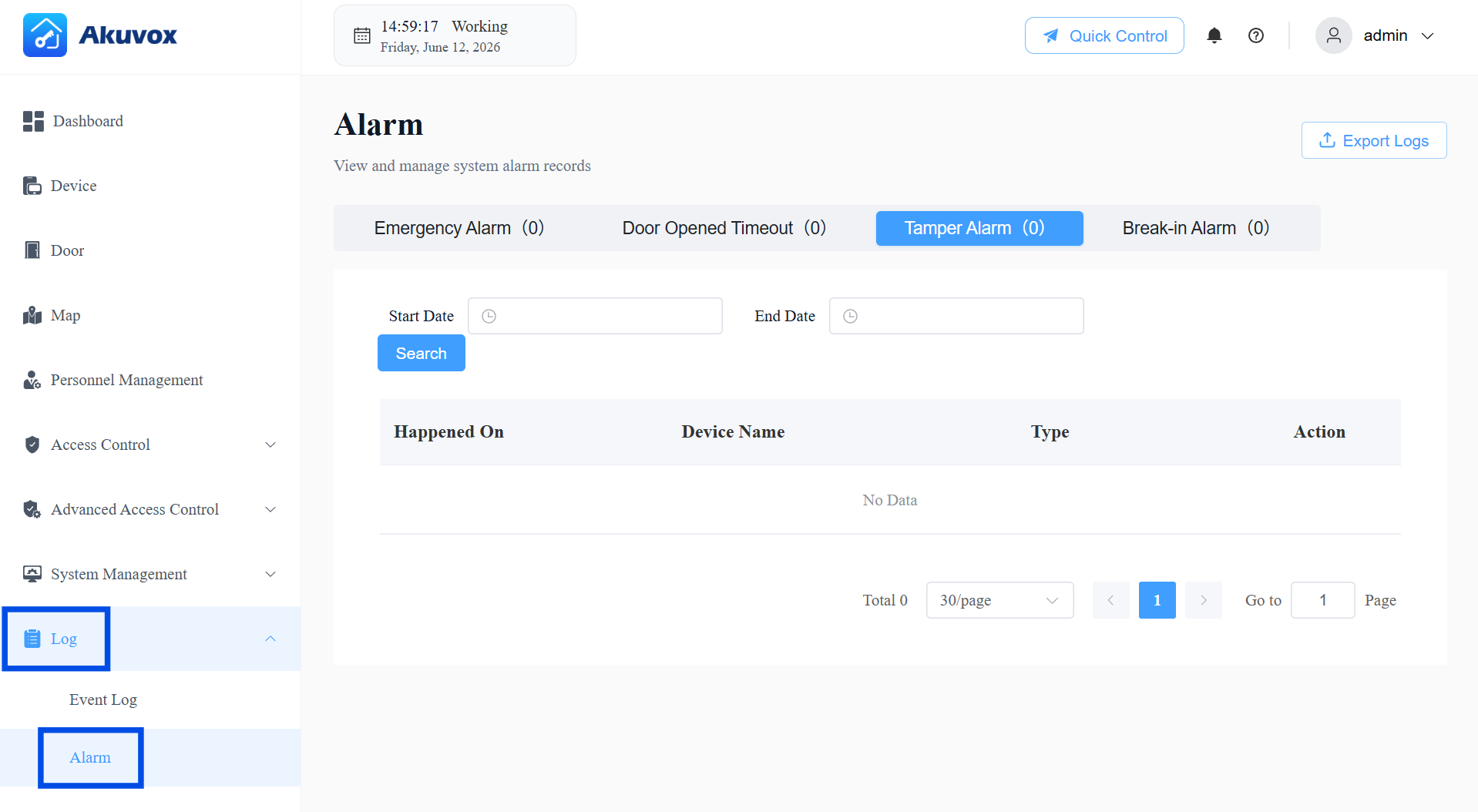
Tamper Alarm
Go to Log > Alarm > Tamper Alarm.
When the device’s tamper alarm is triggered, the alarm will be recorded.
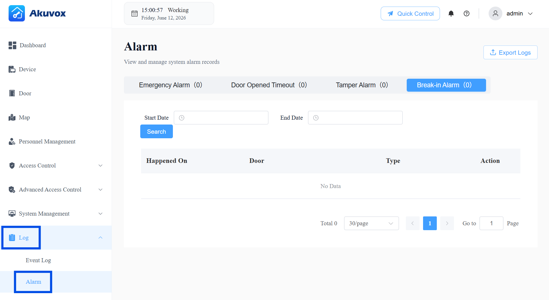
Break-in Alarm
Go to Log > Alarm > Break-in Alarm.
When someone forcibly opens doors, the break-in alarm will be triggered and recorded.
Part 13: System Management
License Validity
ACMS Pro Version 1.0.0.4 is currently a free trial version, valid for 180 days from installation, based on the server's system clock. Keep the clock accurate to avoid unexpected expiration.
When the trial expires, all users (including those already logged in) will be logged out and unable to log back in until the license is renewed.
Data Backup
Protect your system's data by scheduling automatic backups and managing backup files — so you can restore your configuration if something goes wrong, or migrate data to another system.
Automatic Backup
To make sure your system data is backed up regularly without manual effort:
Go to System Management > Data Backup.
In the Backup Settings section, make sure Auto Backup is turned on (it's enabled by default). If you turn it off, the system will not create backups automatically, and you'll need to create them manually.
Choose how often you want backups to run under Backup Frequency:
Daily – a backup is created every day at 02:00.
Weekly – a backup is created every Monday at 02:00.
Monthly – a backup is created on the 1st of each month at 02:00.
Set Max Backup Count (1–100, default is 10) to control how many backup files the system keeps. Once this number is reached, the oldest backup is automatically deleted to make room for new ones — so you don't need to clean up old files yourself.
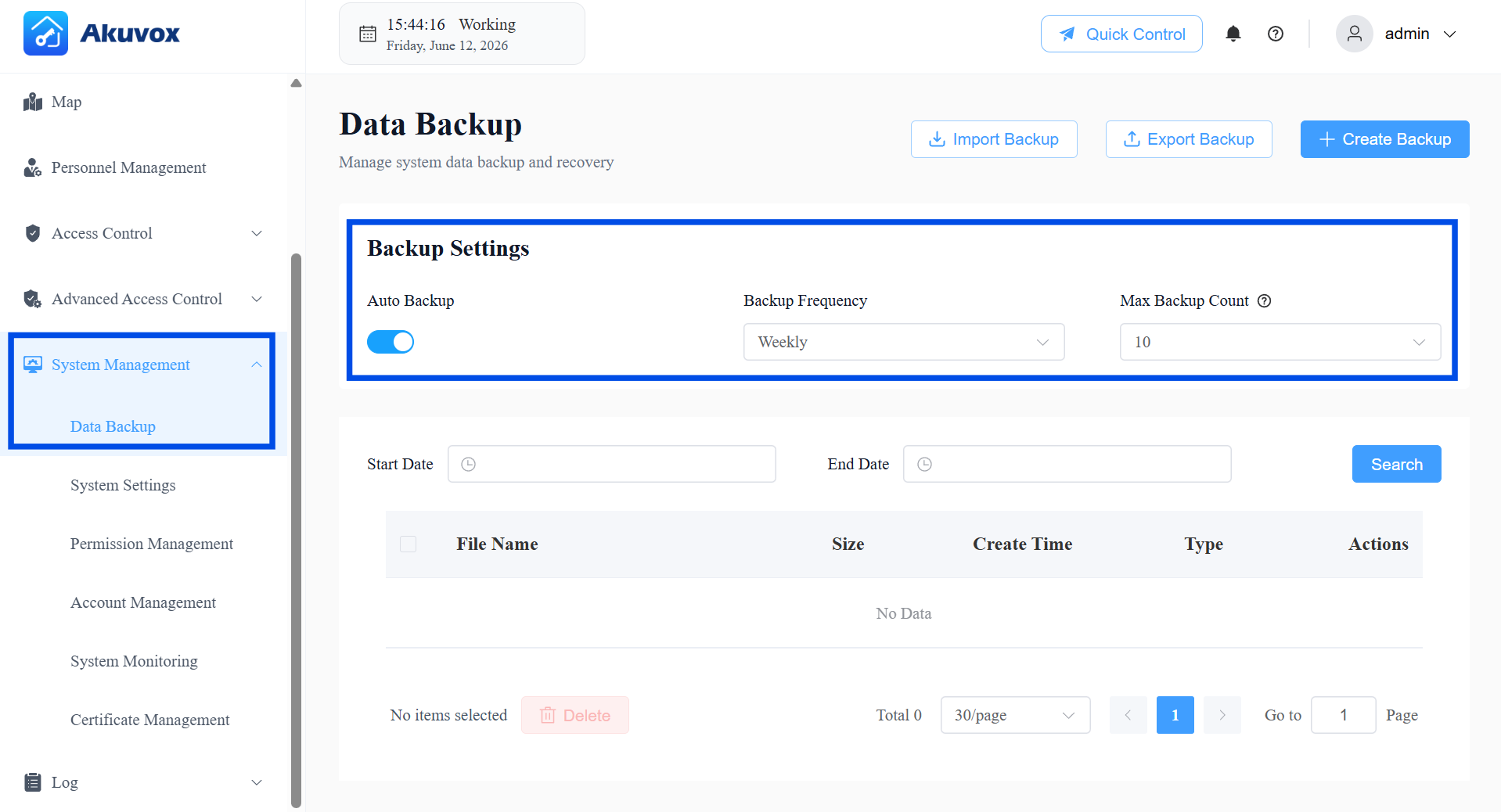
Click Save Changes.
Manual Backup
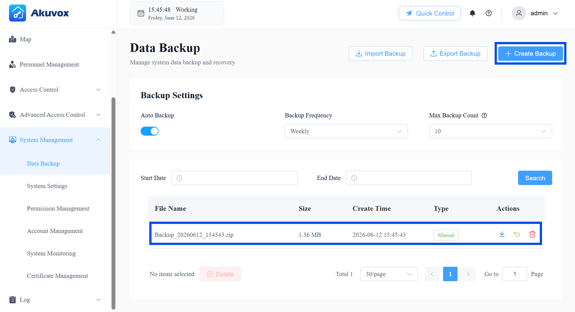
If you want a backup right now — for example, before making major configuration changes:
Click + Create Backup at the top of the page.
A confirmation will appear once the backup has been created and added to the list below.
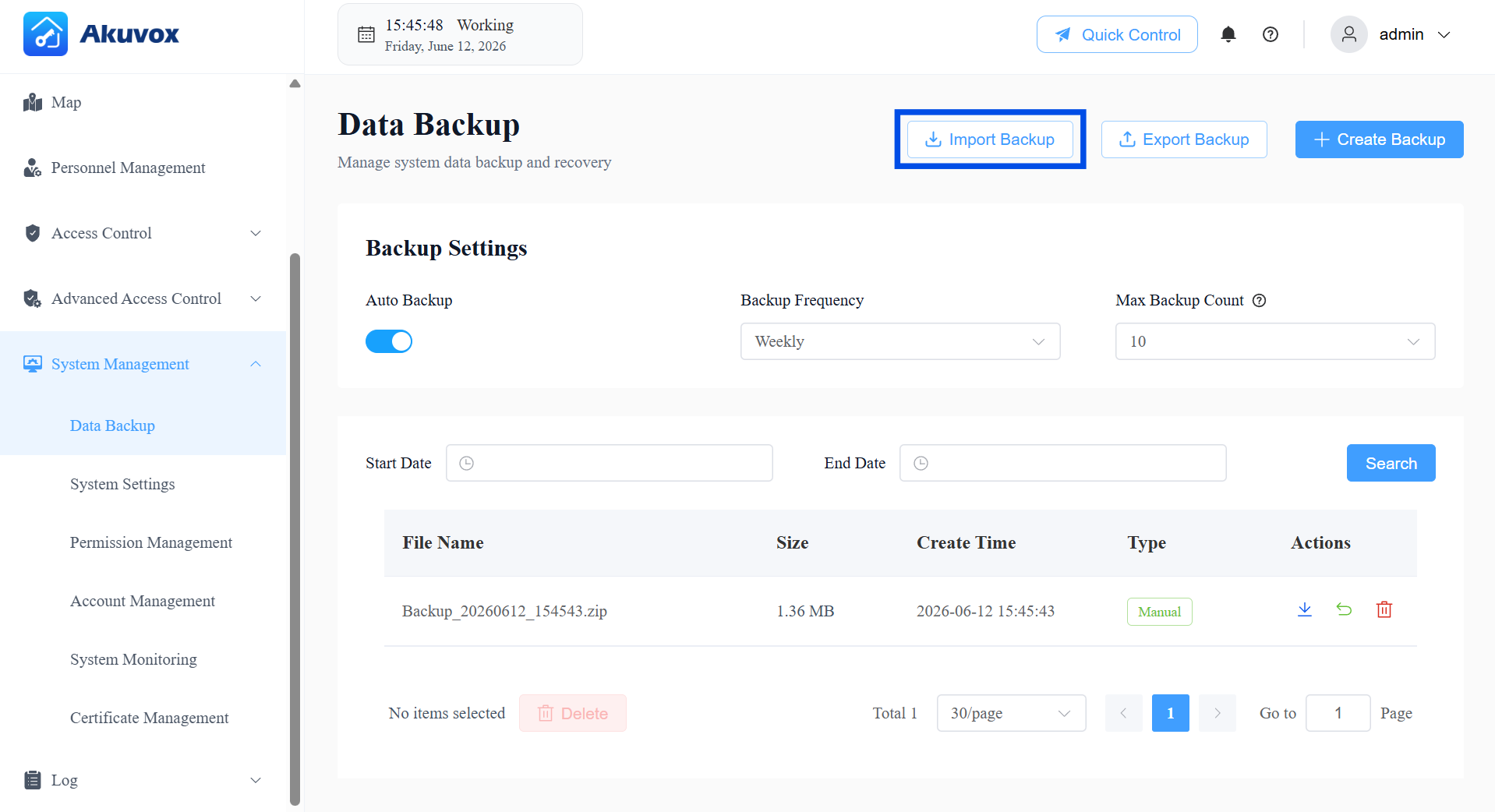
Download Backups
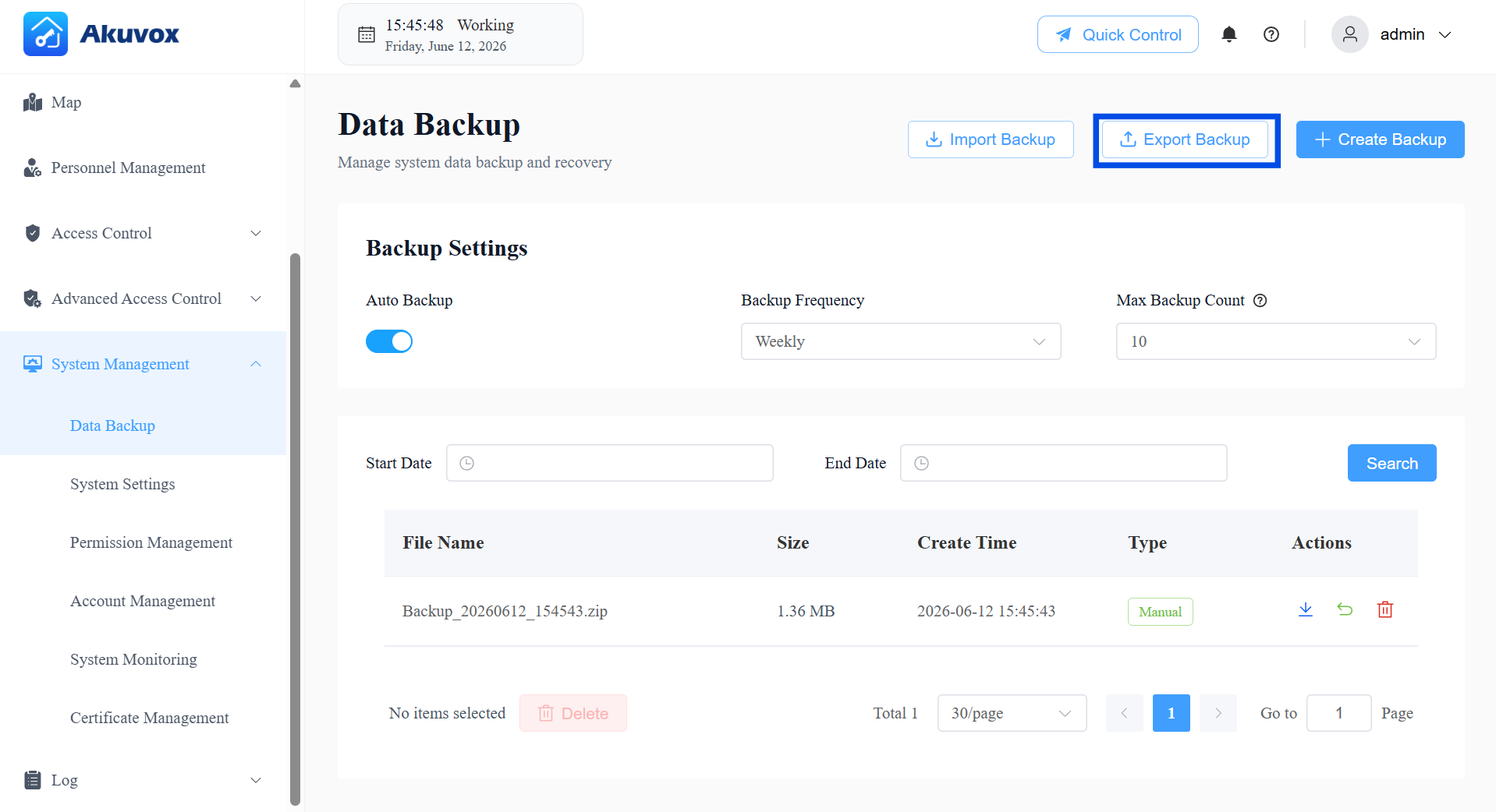
All backups — automatic and manual — appear in the Backup List.
To find a backup from a specific time period, set a Start Date and End Date, then click Search.
To download all backup files at once, click Export Backup.
Restore from a Backup
Restoring from a backup overwrites all current system data — including any personnel, devices, and logs added after the backup was made. This action cannot be undone. Before restoring, it is strongly recommended to first click + Create Backup to save the current state.
Click Import Backup.
Select a backup file from your computer — only .zip files are supported.
The file will upload automatically. Once it finishes, a confirmation message will let you know the restore was successful.
System Settings
Client Settings
The Server Address setting determines which server the PC Client connects to when logging in.
This is the same configuration shared with the Server Address field on the PC Client's login page — updating it from either location applies to both. Once saved here, the PC Client will use this address as the server address for all future logins.
To update the server address:
Go to System Management > System Settings > Client Settings.
Enter the new server address.
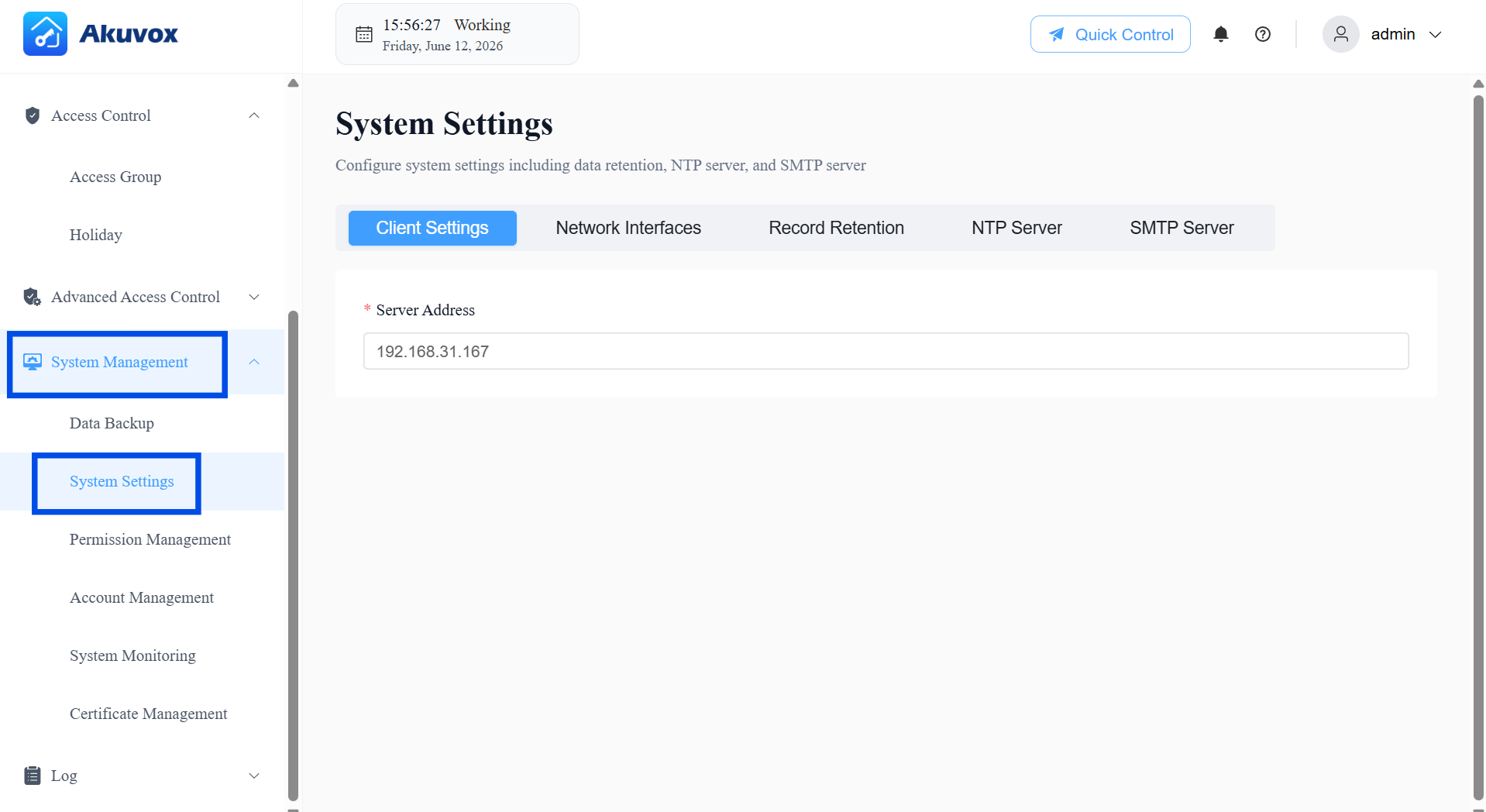
Click Save Changes.
Network Interfaces
This setting controls which network card the server uses to communicate with devices. It does not affect how you access the web management portal.
To configure the network interface:
Go to System Management > System Settings > Network Interfaces.
Under Network Interface Card, select the network card you want the server to use for device communication. By default, this is set to the first network card detected with an IP address.
Once a card is selected, the IP address will display. Choose the IP address you want the server to use.
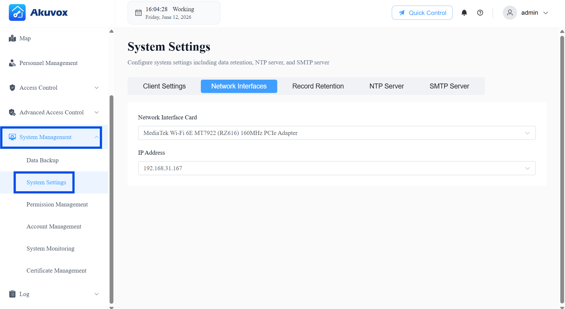
Click Save Changes.
Record Retention
You can control how long different types of system records are stored before being automatically deleted.
Go to System Management > System Settings > Record Retention.
For each log type listed, set how long records should be kept under Keep for.
Select the retention period unit: Day, Week, or Month. For example, "Keep for 30 Days" or "Keep for 6 Months."
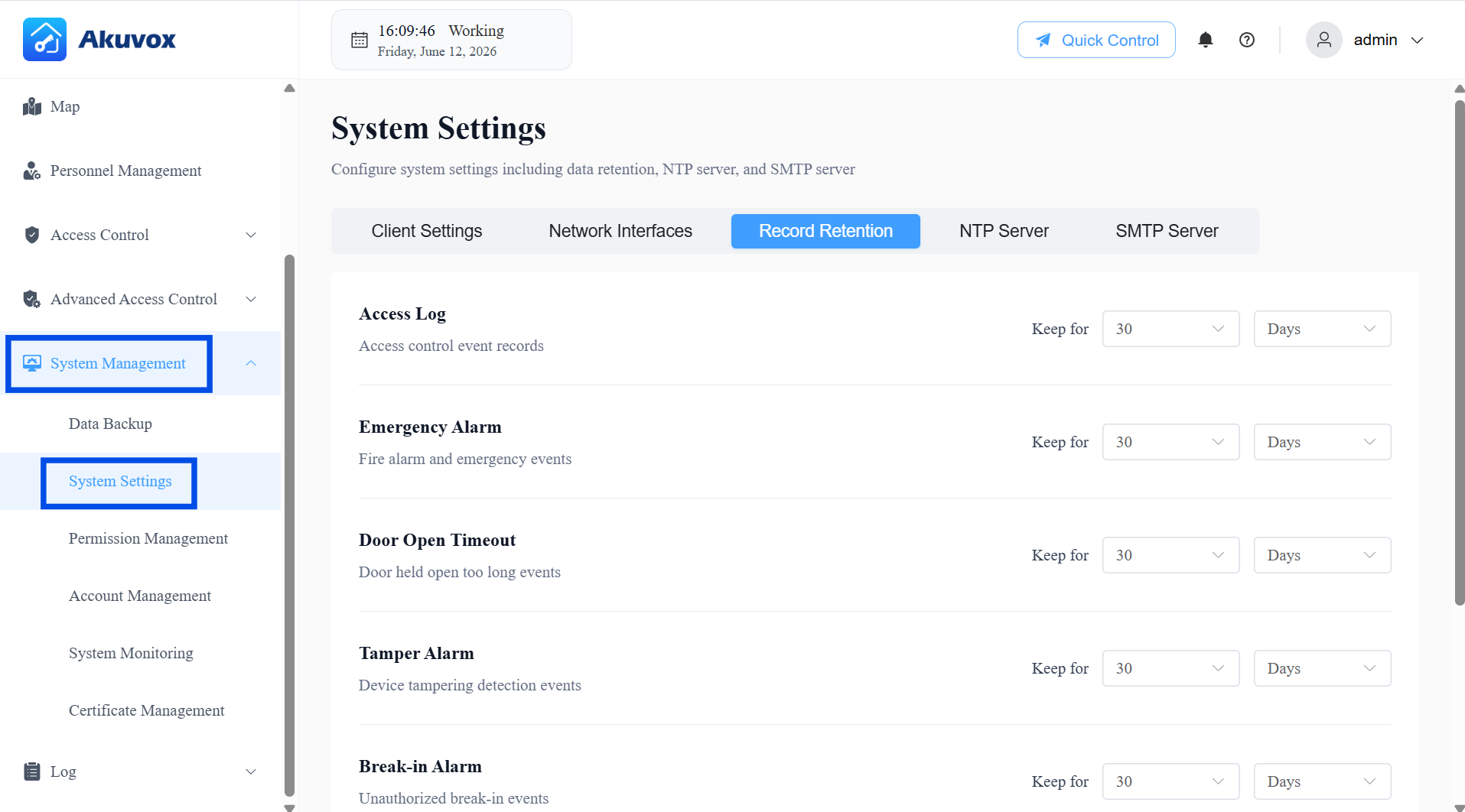
Click Save Changes.
Note
If you shorten the retention period for a log type, any existing records older than the new limit will be permanently deleted once you save.
NTP Server
You can configure NTP (Network Time Protocol) settings to keep your devices' clocks synchronized automatically.
Go to System Management > System Settings > NTP Server.
Turn on Enable NTP to allow the system to automatically sync its time with an NTP server. If left off (the default), no NTP-related settings will be sent to devices.
Enter the address of the Primary Server (required when NTP is enabled). This can be a domain name or IP address.
Optionally, enter a Secondary Server address as a backup. If the Primary Server becomes unavailable, the system will automatically switch to the Secondary Server to keep time synchronized.
Set the Update Interval (minutes). This controls how often devices sync their time with the NTP server, with a range of 60–1000 minutes.
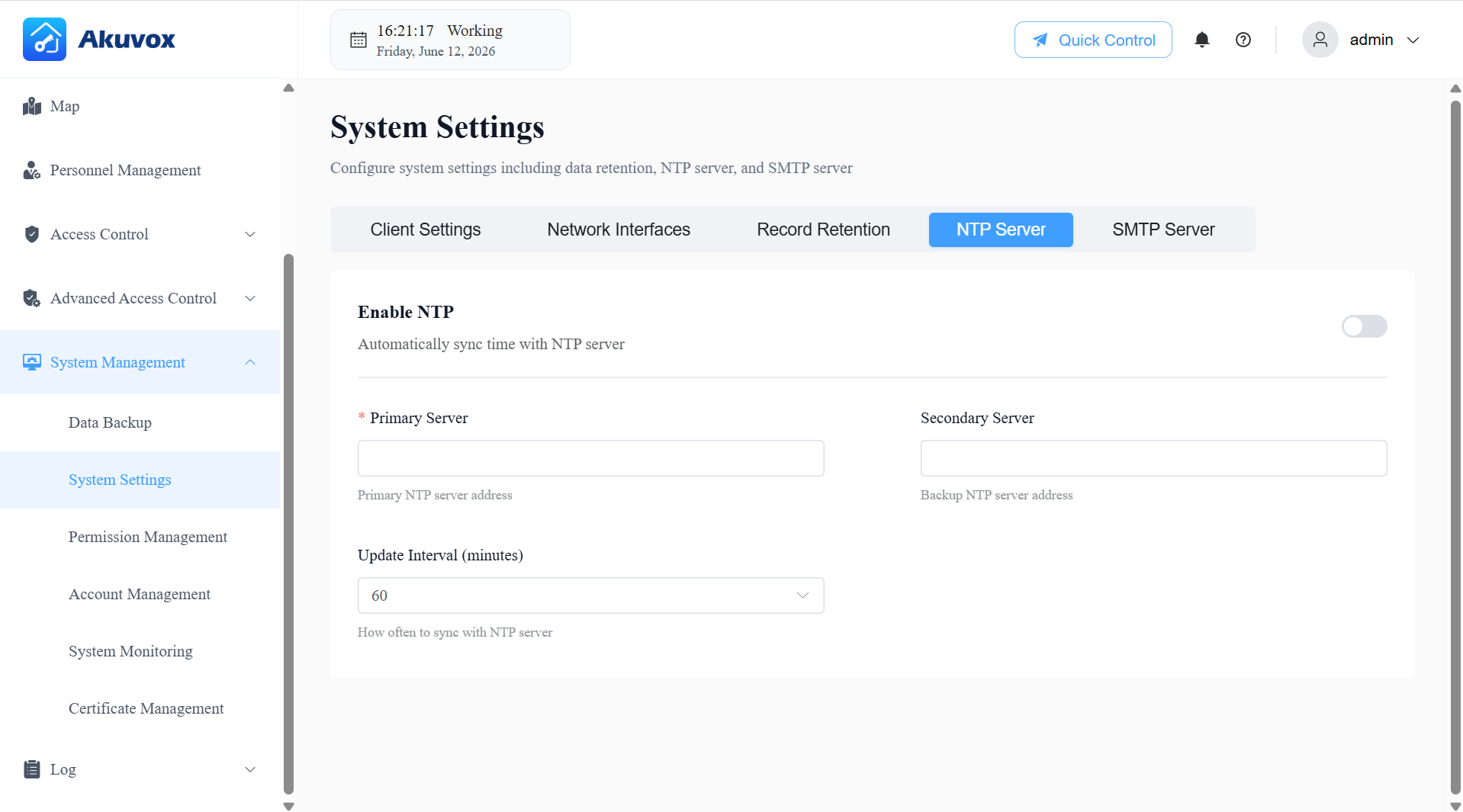
Click Save Changes.
SMTP Server
You can configure an SMTP (email) server so the system can send email notifications — such as alerts and alarms — to users.
Go to System Management > System Settings > SMTP Server.
Turn on Enable SMTP to activate email functionality on the system.
Enter your SMTP Server Address (e.g.,
smtp.gmail.com). This can be a domain name or IP address.Enter the Port number for your SMTP server. Common values are 587 (TLS), 465 (SSL), or 25 (Plain). The valid range is 1–65535.
Enter your Username (e.g.,
user@example.com) and Password for the email account. Both fields support up to 63 characters.
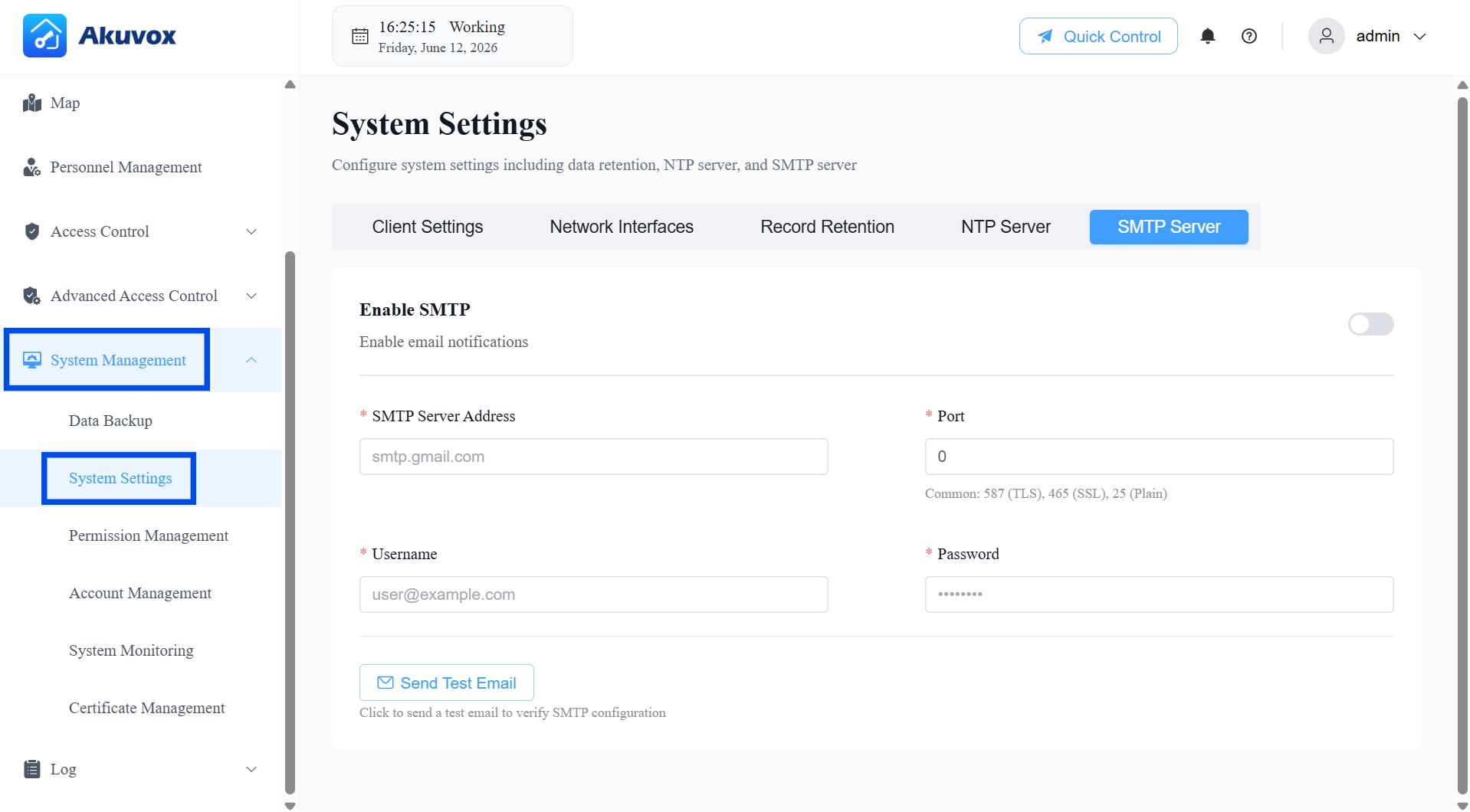
Click Save Changes.
Click Send Test Email to send a test message using the configured SMTP settings.
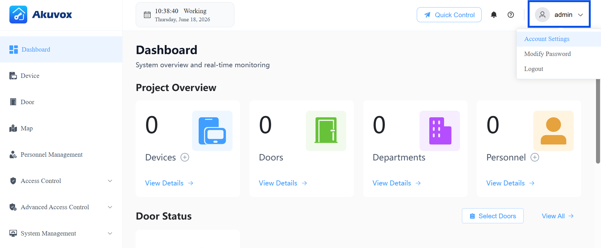
Your Account
Click your username (admin, shown in the top-right corner) to access the following options:
Account Settings: Update your display name and associated email address.
Modify Password: Change your login password directly.
Logout: Sign out of ACMS Pro.
Update Account Settings
Click your username in the top-right corner, then click Account Settings.
Update your Name and/or Email as needed.
Click Submit to apply the changes.
Modify Password
Click your username in the top-right corner, then click Modify Password.
Enter your current password, then enter and confirm a new password.
Click Submit. You may be asked to log in again with the new password.
Logout
Click your username in the top-right corner, then click Logout to end your session.
Part 14: Permission Management
With the Super Admin account, you can manage user roles and control what each role can access within the system. It's only visible to accounts with Super Admin privileges.
Default Roles
The system comes with three built-in roles:
Super Admin: Has full access to all system functions and settings. This role cannot be edited or deleted.
Administrator: Has access to all functions except Device and System Management. Can be edited or deleted.
Monitor: Has access only to Dashboard, Map, and Logs. Can be edited or deleted.
Create a New Role
Click System Management > Permission Management > + Add Role.
Enter the role name and description.
Select permission(s) granted to the role.
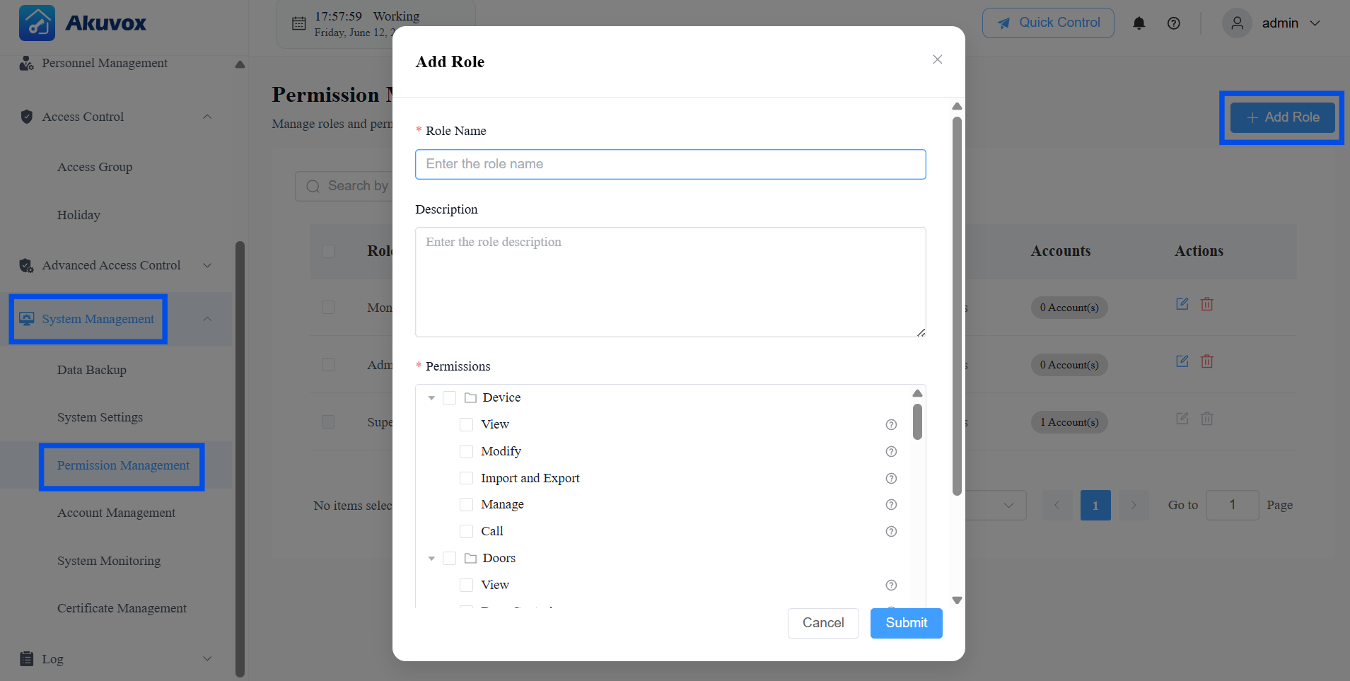
Click Submit.
Part 15: Account Management
With the Super Admin account, you can manage all user accounts in the system.
Add an Account
Click System Management > Account Management > +Add Account.
Enter the username, which is the login username.
Enter the name, which is used to distinguish from other accounts.
Enter the email address, which is used to reset the login password.
Select the account role.
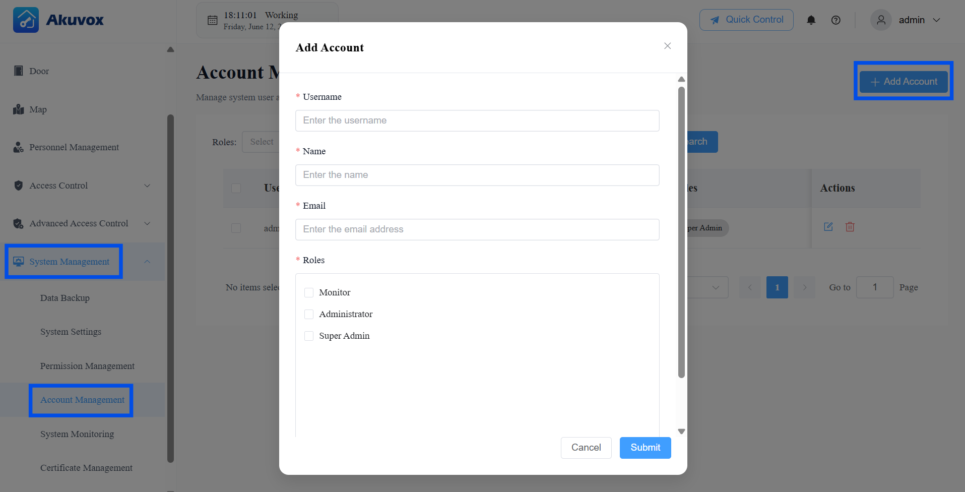
Click Submit.
Part 16: Certificate Management
You can manage the SSL/TLS certificate used to secure connections to the server. The system uses HTTPS for all web access, PC Client access, and HTTP API calls. If no valid certificate is installed, your browser will show a "not secure" warning when accessing the web portal — this is expected until a certificate is configured.
To access the system without browser security warnings, follow these steps:
Generate a self-signed certificate (or obtain one from a certificate authority). This will produce two files: a .crt file (the certificate, containing the public key) and a .key file (the private key).
Go to System Management > Certificate Management.
Click Upload Certificate to upload both files to the server.
Add the .crt file to your browser's trusted certificate list. This step tells your browser to trust the certificate, removing the "not secure" warning.

Glossary
Term | Definition |
|---|---|
Access Group | A reusable permission template defining who can open which doors and during which time windows. |
Anti-Passback | A security rule preventing a credential from being used for the same direction of travel (entry or exit) twice in a row without the corresponding opposite action in between. |
Break-in Alarm | An alarm triggers when a door is opened by force, without a valid access credential. |
Controlled Relay | The relay output on a device that is wired to the door lock. |
DPS | Door Position Sensor — the label for door sensor input ports on A095 devices (DPS1~4). |
DTMF | Dual-Tone Multi-Frequency — the tones generated by a keypad. Used as a door-open trigger when a specific code is dialed. |
First Credential In | A door mode where the door begins a hold-open period after the first valid credential is presented. |
Holiday Exemption | A setting on an Access Group that allows its members to retain normal access permissions even during a configured Holiday period. |
Interlock | A rule preventing multiple linked doors from being open simultaneously. |
Lockdown | A door state in which all normal access methods are disabled; only users with Lockdown Bypass can open the door. |
Lockdown Bypass | A personnel privilege that allows the person to open a door even when it is in Lockdown state. |
NTP | Network Time Protocol — used to synchronize the system clock and device clocks automatically. |
REX | Request to Exit — the label for exit button input ports on A095 devices (REX1~4). |
RS485 | A communication interface standard used to connect external card readers or other peripheral devices to a door phone or access controller. |
RTSP | Real Time Streaming Protocol — used by third-party NVR/VMS platforms to pull video streams from door phone cameras. |
SMTP | Simple Mail Transfer Protocol — the standard used to send email notifications from the system. |
Tamper Alarm | An alarm triggered when a device detects that someone is attempting to remove or tamper with it. |
Wiegand | A communication interface standard commonly used to connect external card readers to access control devices. |
WatchDog Service | A background service that monitors the ACMS Pro Server process and attempts automatic recovery if it becomes unresponsive. |