Unlock by Public PIN Code
There are two types of PIN codes for door access: public and private. A private PIN is unique to each user, while the public one is shared by residents in the same building or complex. You can create and modify both the public and private PIN codes.
Set it up on the web Access Control > PIN Setting > Public Key interface.

PIN Code: Set 5 to 8 digits for opening doors. The default is 33333333.
User-specific Access Methods
The private PIN code, RF card, face, and license plate settings should be assigned to a particular user for door opening.
When adding a user, you can also customize settings such as defining the door access schedule to determine when the code is valid and specifying which relay to open.
To add a user, go to Directory > User interface and click +Add.

User ID: The unique identification number assigned to the user.
Name: The name of this user.
Unlock by Private PIN
Users can open doors by entering their private PINs on the keypad.
On the Directory > User > +Add interface, scroll to the Private PIN section.

Code: Set a 2-8 digit PIN code solely for the use of this user. Each user can only be assigned a single PIN code.
You can enable/disable the use of the private PIN code on the web Access Control > PIN Setting > Private PIN interface. It is enabled by default.

Unlock by QR Code
The device supports scanning on-premise-generated and SmartPlus Cloud-generated QR codes.
On the Directory > User > +Add interface, scroll to the Private PIN section. Click the QR code icon .
.
Click Generate to generate the QR code with an 8-digit PIN.
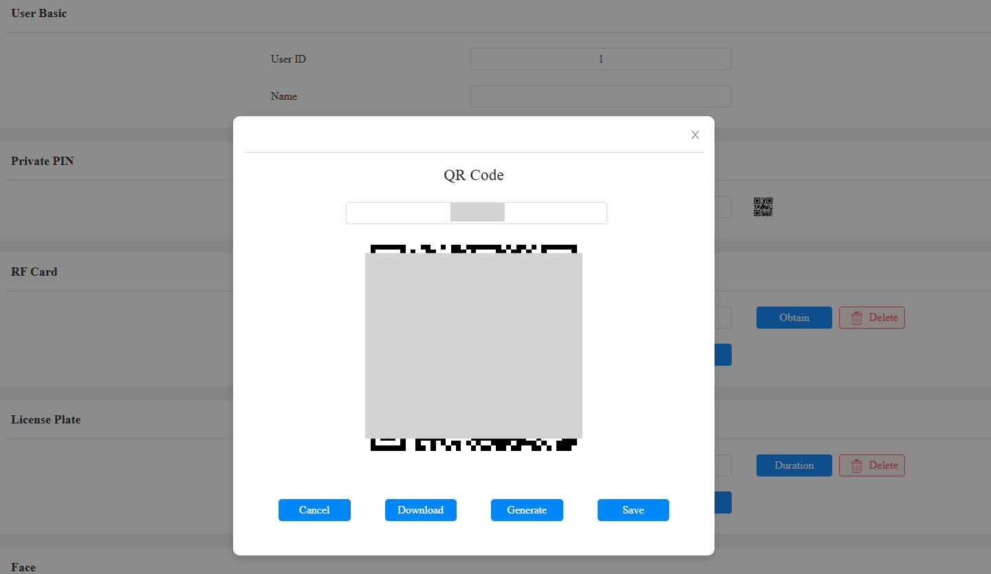
Cancel: Click to return to the user editing interface. The QR code and the PIN code will not be saved.
Download: Click to save the QR code to your PC.
Generate: Click to generate another QR code and PIN code.
Save: Click to return to the user editing interface and save the codes.
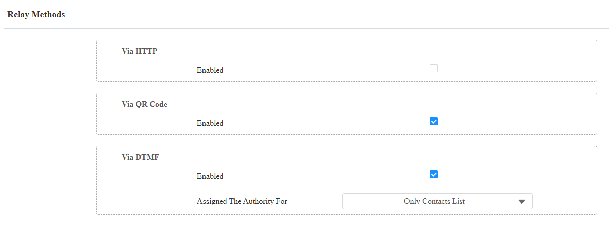
You enable or disable the use of QR code on the Access Control > Relay > Open Relay Methods interface.
It is enabled by default.
Unlock by RF Card
On the Directory > User > +Add interface, scroll to the RF Card section.

Code: The card number that the card reader reads.
Note:
Each user can have a maximum of 5 cards added.
The device allows adding 5,000 users.
RF cards operating at 13.56 MHz frequencies are compatible with the device for access.
You can enable and disable the use of RF cards on the Access Control > Card Setting interface.

RF Card Code Format
To integrate the RF card door access with the third-party intercom system, you need to match the RF card code format with the one used by the third-party system.
To set it up, go to Access Control > Card Setting > RFID interface.

IC Card Display Mode: Set the card number format from the provided options.
Unlock by License Plate
Akuvox offers two main ways to identify vehicles and open gates.
Use a third-party LPR(License Plate Recognition) camera to recognize the license plate of the vehicle.
Use the Akuvox long-range card reader ACR-CPR12 to recognize the UHF card attached to the vehicle's windshield.
To assign the license plate to a user, find the License Plate part on the Directory > User > +Add interface.

Add: A user can have up to 5 license plates.
Duration: Enable/disable Long-term Vehicle. It is enabled by default. If disabled, specify when the vehicle can enter or exit the parking lot.
Unlock by Facial Recognition
On the Directory > User > +Add interface, scroll to the Face section. Click Import to upload the picture and Reset to remove it.

Import: Click to upload the face picture.
Obtain: Click to start enrolling a face on the device side.
Reset: Click to remove the registered face image.
Note
Support Format: jpg, png. Size: a maximum of 2 MB.
Facial Recognition Settings
The device allows you to adjust facial recognition accuracy, recognition intervals, and more to enhance user experience.
To set it up, go to the Access Control > Face Setting interface.
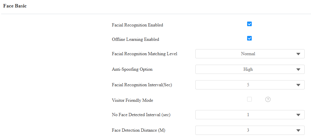
Facial Recognition Enabled: Enable/disable the facial recognition function.
Offline Learning Enabled: Facial recognition accuracy improves as the number of facial recognition increases.
Facial Recognition Matching Level: Determine how strict the facial recognition system is in comparing a person’s face with uploaded face data. Each level allows a different degree of difference or face covering (excluding the mouth area) to pass the recognition.
- Low: Allow slight differences from the uploaded face data, with little face coverage.
- Highest: Require the face to be identical to the uploaded one, with minimal or no covering.
- The other two levels are in between.
Anti-Spoofing Option: Set how strict the system is in preventing fake faces.
- Close: Disable the facial anti-spoofing function. Facial verification can be passed using non-living substitutes for an authorized person's face, such as a photo.
- Highest: The system cannot be fooled by any non-living substitutes for an authorized person's face.
- The other three levels are in between.
Facial Recognition Interval(Sec): Adjust the time interval between each facial recognition attempt, ranging from 1 to 8 seconds.
Visitor Friendly Mode: Set whether to give auditory or visual prompts when recognition fails. Disabled by default.
No Face Detected Interval(Sec): Adjust the time interval between each detection, ranging from 1 to 8 seconds.
Face Detection Distance(M): Adjust the detection distance, ranging from 1 to 3 meters.
Unlock by Bluetooth
The device supports opening the door via Bluetooth-enabled My MobileKey or SmartPlus App. Users can either open the door with the apps in their pockets or wave their phones towards the device as they get closer to the door.
Note
Before using Bluetooth to open doors, you need to enable the Bluetooth function on the Access Control > BLE interface.
Unlock via My MobileKey
On the Directory > User > +Add interface, scroll to the BLE Setting section.

Authentication Code: Click Generate to generate a 6-digit verification code.
Bluetooth Unlock Settings
Set up the Bluetooth-unlock feature on the Access Control > BLE interface.
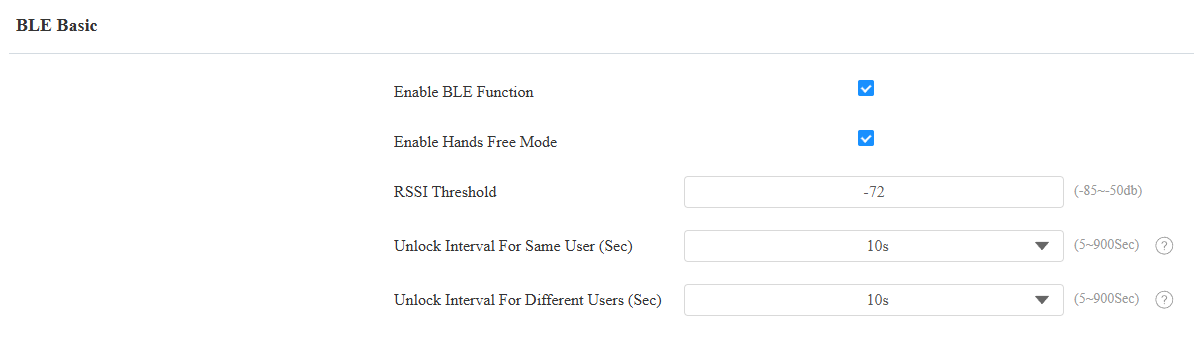
Enable Hands Free Mode: If enabled, users can gain door access hands-free. If disabled, users have to wave their hands near the device to open doors.
RSSI Threshold: Set the received signal strength. Higher values indicate stronger signal strength, making it easier to receive the Bluetooth signal.
Unlock Interval For Same User(Sec): Set the time interval between consecutive Bluetooth door access attempts for the same user.
Unlock Interval For Different Users(Sec): Set the time interval between consecutive Bluetooth door access attempts for different users.
Note
To learn about detailed configuration steps of different Bluetooth-based access methods, you can click the following articles.
Access Setting
You can customize access settings, such as defining the door access schedule to determine when the code is valid and specifying which relay to open.
On the Directory > User > +Add interface, scroll to the Access Setting section.
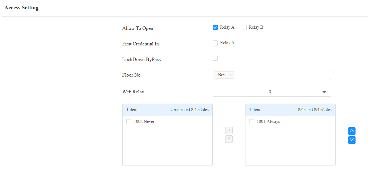
Allow To Open: Enable the door to be opened.
First Credential In: This decides whether the user can keep the door open during the scheduled time after activating it.
Lockdown Bypass: This decides whether the user can open the door when the door is locked during the scheduled time.
Floor No. : Specify the accessible floor(s) to the user via the elevator.
Web Relay: Specify the ID of the web relay action commands that you’ve configured on the Web Relay interface. A default value of 0 indicates that the web relay will not be triggered.
Schedule: Grant the user access to open designated doors during preset periods by relocating the desired schedule(s) from the left box to the right one. Besides custom schedules, there are 2 default options:
Always: Allows door opening without limitations on door open counts during the valid period.
Never: Prohibits door opening.
Import/Export User Data
The device supports access control user data being shared among Akuvox devices through import and export.
Click here to view how to import and export user data between Akuvox devices.
To set it up, go to the Directory > User interface. The device supports up to 5,000 users.

Import: The supported format is TGZ.
Export: The supported format is CSV or XML.
Unlock by NFC
NFC (Near Field Communication) is a popular way for door access. It uses radio waves for data transmission interaction. The device can be unlocked by NFC. You can keep the mobile phone closer to the device for door access.
To set it up, go to the Access Control > Card Setting > Card Type interface.

Note
The NFC feature is not available on iPhones.
Click here to view how to open doors via NFC.
Mifare Card
The device can read encrypted Mifare cards for greater security. When this feature is enabled, it reads the data in the cards’ designated sectors and blocks, not the UID.
Click here to view the details of encrypting and reading Mifare cards.
To set it up, go to Access Control > Card Setting > Mifare Card Encryption interface.

Classic:
Sector/Block: Specify the location where encrypted card data is stored. A Mifare card has 16 sectors (numbered 0 to 15), and each sector has 4 blocks (numbered 0 to 3).
Block Key: Set a password to access the data stored in the predefined sector/block.
Plus: You can set up three choices. This means you can use three types of Mifare Plus cards. When swiping a card, as long as one of the choices matches its SL key, the card code in the block you specified will be output.
Block: Specify the block(s) to be read.
SL1: The key number within 32 bits.
SL3: The key number within 32 bits.
DESFire:
App ID: A 6-digit hexadecimal number
File ID: The ID of the encrypted file of the app, which can be a number from 0 to 16.
Crypto: The encryption method.
Key: The file key.
Key Index: The index number for the key, which can be a number from 0 to 11.
Unlock by DTMF Code
Dual-tone multi-frequency signaling(DTMF) is a way of sending signals over phone lines by using different voice-frequency bands. Users can use the DTMF function to unlock the door for visitors during a call by either typing the DTMF code on the soft keypad, or tapping the unlock tab with the DTMF code on the screen.
To configure DTMF codes, go to Access Control > Relay interface.
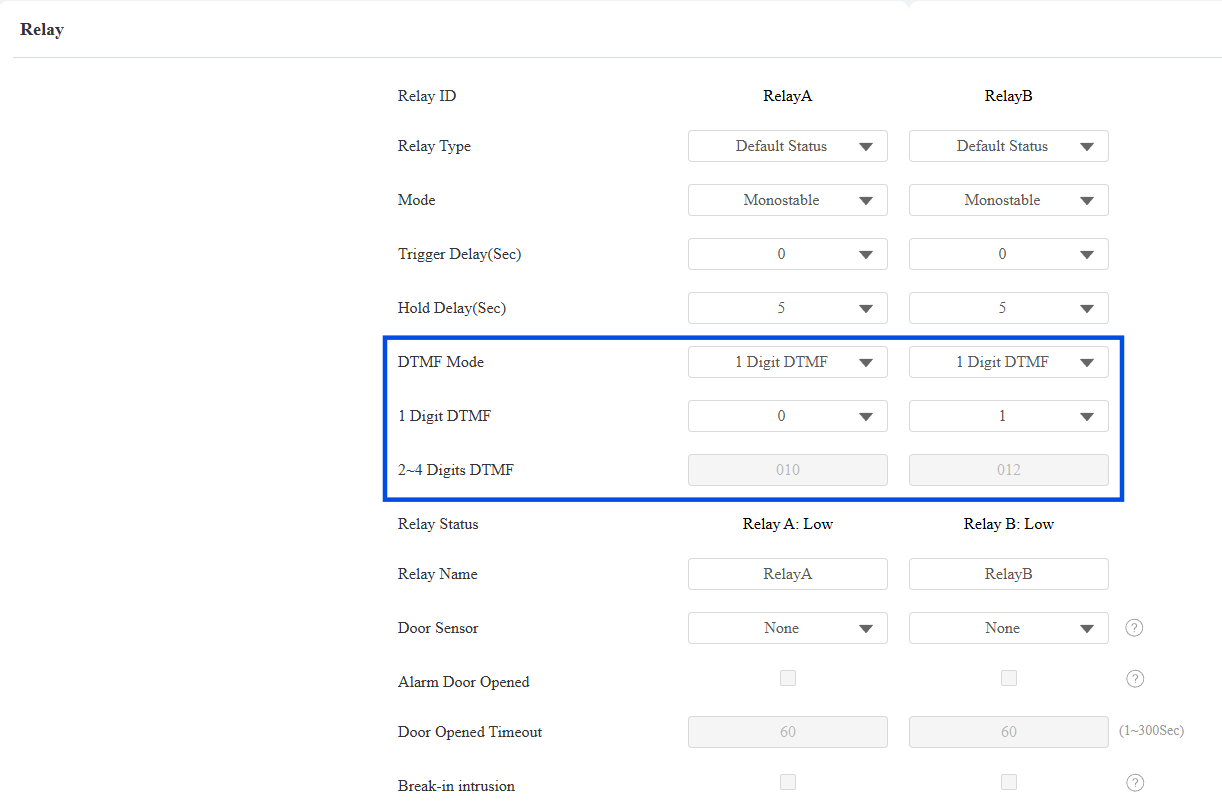
DTMF Mode: Set the number of digits for the DTMF code.
1 Digit DTMF: Define the 1-digit DTMF code within the range(0-9 and *,#) when the DTMF Mode is set to 1-digit.
2-4 Digit DTMF: Set the DTMF code based on the number of digits selected in the DTMF Mode.
Note
To open the door with DTMF, the intercom devices that send and receive the unlock command must use the same mode and code. Otherwise, the DTMF unlock may fail. See here for the detailed DTMF configuration steps.
DTMF White List
To secure door access via DTMF codes, you can set up the DTMF whitelist on the device web Access Control > Relay > Relay Methods interface so that only the caller numbers you designated in the device can use the DTMF code to gain door access.
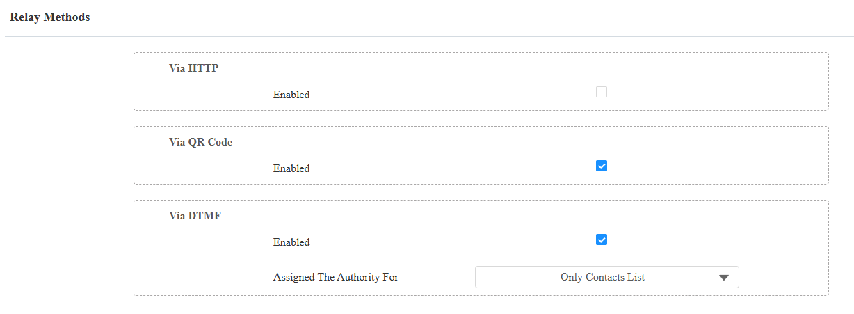
Assigned The Authority For: Specify the contacts authorized to open doors via DTMF:
Only Contacts List: Doors can be opened by numbers added to the device's contact list and pressing the push button.
All Numbers: Any numbers can unlock using DTMF.
DTMF Data Transmission
In order to achieve door access via DTMF code or some other applications, you are required to properly configure DTMF in order to establish a DTMF-based data transmission between the device and other intercom devices.
DTMF Type Differences:
Inband | DTMF signals are transmitted within the same audio channel as voice data. Simple implementation but signal distortion may occur with highly compressed codecs (e.g., G.729). |
RFC2833 | Transmits DTMF as special event packets over RTP (Real-Time Transport Protocol), known as out-of-band transmission. Reliable and unaffected by codecs. |
Info | Sends DTMF signals via SIP (Session Initiation Protocol) signaling channel. Separate from voice transmission, ensuring audio quality. |
Info+Inband | Combines Info and Inband methods. |
Info+RFC2833 | Combines both Info and RFC2833 methods. |
Info+Inband+RFC2833 | All three methods are used simultaneously. |
Set it up on the Intercom > Account > DTMF interface.

Type: Select from the following options: Inband, RFC2833, Info, Info+Inband, Info+RFC2833, based on the specific DTMF transmission type of the third-party device to be matched with as the party for receiving signal data.
How to Notify DTMF: Select Disabled, DTMF, DTMF-Relay, or Telephone-Event according to the specific type adopted by the third-party device. You are required to set it up only when the third-party device to be matched with adopts Info mode.
Payload: Set the payload according to the specific data transmission payload agreed on between the sender and receiver during the data transmission.
Unlock by HTTP Commands
The device supports remote door unlocking via an HTTP command. Simply enable this feature and input the HTTP command (URL) for the device. This will trigger the relay and open the door, even if the users are away from the device.
Set it up on the Access Control > Relay > Open Relay Methods interface.
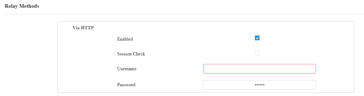
Session Check: Enable to enhance data transmission security.
Username: Set a username for authentication in HTTP command URLs.
Password: Set a password for authentication in HTTP command URLs.
Tip
Here is an HTTP command URL example for relay triggering.

Note
The HTTP format for relay triggering varies depending on whether the device's high secure mode is enabled. Please refer to this how-to guide Opening the Door via HTTP Command for more information.
Unlock by Exit Button
When users need to open the door from inside by pressing the Exit button, you need to set up the Input terminal that matches the Exit button to activate the relay for the door access.
Click here to watch the instruction video.
To set it up, navigate to the Access Control > Input interface.
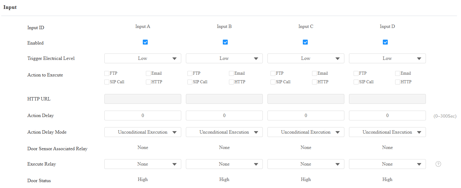
Enabled: To use a specific input interface.
Trigger Electrical Level: Set the input interface to trigger at a low or high electrical level.
Action To Execute: Set the desired actions that occur when the specific Input interface is triggered.
FTP: Send a screenshot to the preconfigured FTP server.
Email: Send a screenshot to the preconfigured Email address.
SIP Call: Call the preset number upon the trigger.
HTTP: When triggered, the HTTP message can be captured and displayed in the corresponding packets. To utilize this feature, enable the HTTP server and enter the message content in the designated box below.
HTTP URL: Enter the HTTP message if selecting HTTP as the action to execute. The format is http://HTTP server’s IP/Message content.
Action Delay: Specify how many seconds to delay executing the preconfigured actions.
Action Delay Mode:
Unconditional Execution: The action will be carried out when the input is triggered.
Execute If Input Still Triggered: The action will be carried out when the input stays triggered. For example, if the door stays open after triggering the input, an action such as an email will be sent to notify the receiver.
Door Sensor Associated Relay: This indicates the Relay bound to the Input when the Input is configured as a Door Sensor. Displays None when the Input is not associated with any Relay.
Execute Relay: Specify the relay to be activated on input trigger. This is incompatible with the break-in intrusion feature. The same input cannot work for both the door sensor and push exit button.
Door Status: Display the status of the input signal.