User-specific Access Methods
The private PIN code, RF card, Bkey, and license plate settings should be assigned to a particular user for door opening.
When adding a user, you can also customize settings such as defining the door access schedule to determine when the code is valid and specifying which relay to open.
To add a user, go to Directory > User interface and click +Add.
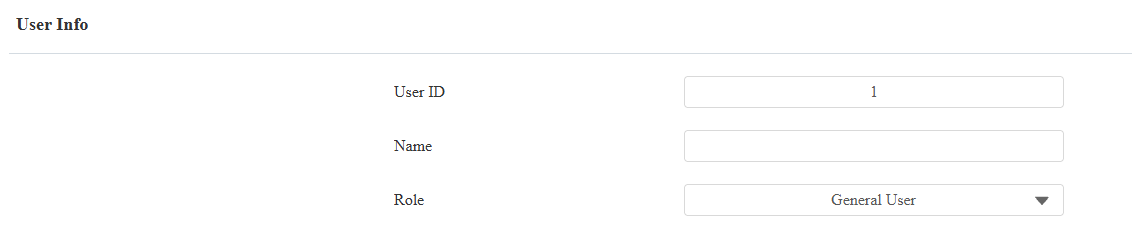
User ID: The unique identification number assigned to the user.
Name: The name of this user.
Role: Define the user as a General User or an Administrator. The Admin card can be used to add a user card. Please refer to Configure Admin Cards and User Cards for detailed configuration.
Unlock by Private PIN
Users can open doors by entering their private PINs on the A13S keypad. For A13C, it can be connected to an external keypad.
On the Directory > User > +Add interface, scroll to the PIN section.

Code: Set a 2-8 digit PIN code solely for the use of this user. Each user can only be assigned a single PIN code.
You can enable/disable the use of the private PIN code and set up the PIN entry interval on the web Access Control > PIN Setting interface.
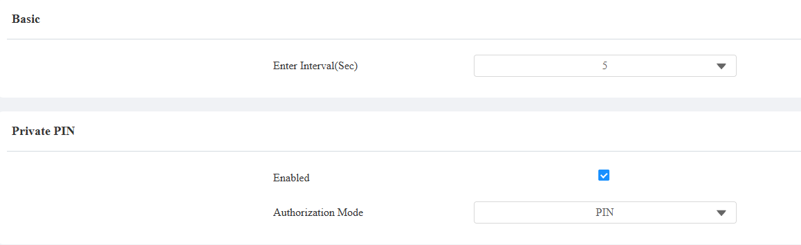
Enter Interval: The maximum interval between consecutive keypad inputs. If no key is pressed within the configured interval, all previously entered digits are cleared. The default value is 5 seconds.
Private PIN Access Mode
El dispositivo proporciona dos métodos de autenticación para el acceso privado por código PIN: PIN y APT# + PIN. Esta última requiere que los usuarios introduzcan su número de apartamento seguido de su PIN privado para desbloquear la puerta.
To set up the authorization mode, go to the Access Control > PIN Setting > Private PIN interface.

Authorization Mode: Set the authentication mode for door access.
PIN: Users are only required to enter their PIN code.
APT#+PIN: Users must first enter the Apartment Number, followed by their PIN code.
Unlock by RF Card/Bkey
Only A13S supports unlocking via Bkey.
On the Directory > User > +Add interface, scroll to the RF Card & Bkey section.
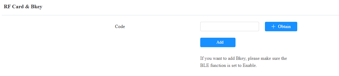
Code: The card number that the card reader reads.
Note:
Each user can have a maximum of 5 cards added.
The device allows adding 20,000 users.
RF cards operating at 13.56 MHz and 125 kHz frequencies are compatible with the device for access.
RF Card Code Format
Para integrar el acceso a la puerta de la tarjeta RF con el sistema de intercomunicación de terceros, necesitas que el formato del código de la tarjeta RF coincida con el que utiliza el sistema de terceros.
To set it up, go to Access Control > Card Setting > RFID interface.
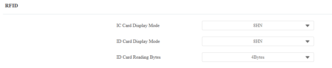
IC/ID Card Display Mode: Set the card number format from the provided options. The default format of the device is 8HN.
ID Card Reading Bytes: Specify card bytes to be read: 3 Bytes or 4 Bytes. The default is 4 Bytes.
Unlock by License Plate
Akuvox ofrece dos formas principales de identificar vehículos y abrir puertas.
Utiliza una cámara LPR (Reconocimiento de Matrículas) de terceros para reconocer la matrícula del vehículo.
Utiliza el lector de tarjetas de largo alcance Akuvox ACR-CPR12 para reconocer la tarjeta UHF acoplada al parabrisas del vehículo.
To assign the license plate to a user, find the License Plate part on the Directory > User > +Add interface.

Add: A user can have up to 5 license plates.
Duration: Enable/disable Long-term Vehicle. It is enabled by default. If disabled, specify when the vehicle can enter or exit the parking lot.
Unlock by Bluetooth
Only A13S supports Bluetooth-related features.
It supports opening the door via Bluetooth-enabled My MobileKey or SmartPlus App. Users can either open the door with the apps in their pockets or wave their phones towards the device as they get closer to the door.
Note
Before using Bluetooth to open doors, you need to enable the Bluetooth function on the Access Control > BLE interface.
Unlock via My MobileKey
On the Directory > User > +Add interface, scroll to the BLE Setting section.

Authentication Code: Click Generate to generate a 6-digit verification code.
You can set up the pairing valid time within which users need to finish the pairing.
To set it up, go to Access Control > BLE > BLE interface.
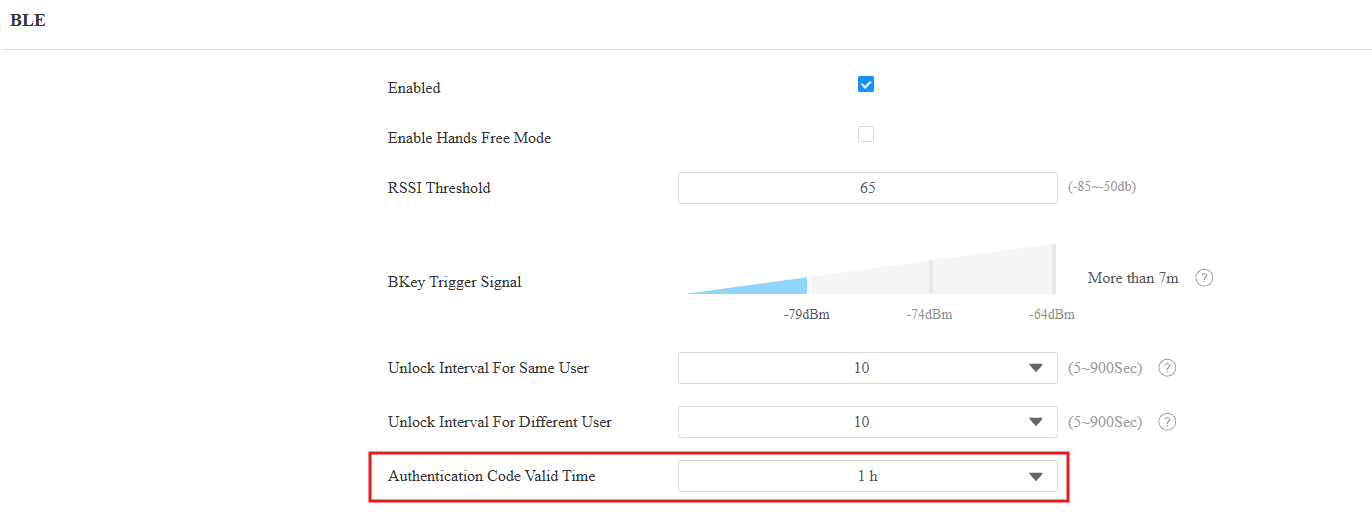
Authentication Code Valid Time: Set the time from 15 minutes to 24 hours, or Forever.
Bluetooth Unlock Settings
Set up the Bluetooth-unlock feature on the Access Control > BLE interface.
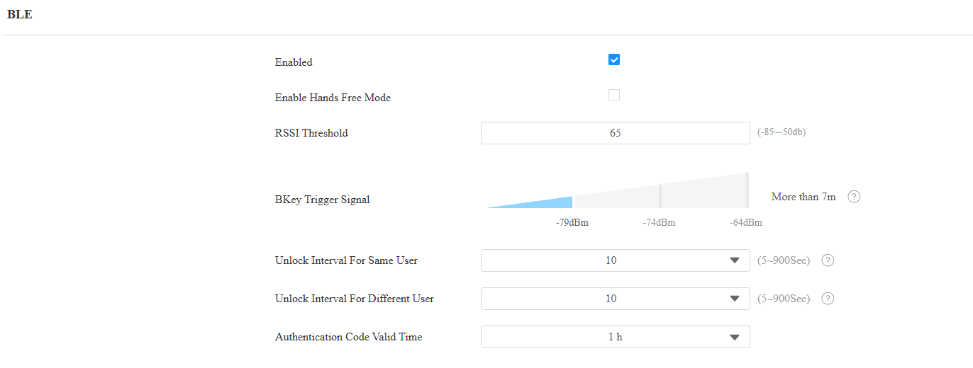
Enable Hands Free Mode: If enabled, users can gain door access hands-free. If disabled, users have to wave their hands near the device to open doors.
RSSI Threshold: Set the received signal strength. Higher values indicate stronger signal strength, making it easier to receive the Bluetooth signal.
Bkey Trigger Signal: Three ranges determine the Bkey trigger distance(1 meter to more than 7 meters).
Unlock Interval For Same User: Set the time interval between consecutive Bluetooth door access attempts for the same user.
Unlock Interval For Different Users: Set the time interval between consecutive Bluetooth door access attempts for different users.
Note
To learn about detailed configuration steps for different Bluetooth-based access methods, you can click the following articles.
Device Info Setting
You can customize the device name and ID for convenient Bluetooth pairing.
To set it up, go to Access Control > BLE > Device Info Settings interface.

Device Name: Limited to 1-63 numbers or characters.
Device ID: Limited to 1-12 numbers or characters.
Movement Detection Settings
This feature only works for Bluetooth-based door opening via the My Mobilekey App. When enabled, users cannot open the door without shaking their mobile phones.
Enable the function on the Access Control > BLE > Movement Detection interface.

Access Setting
You can customize access settings, such as defining the door access schedule to determine when the code is valid and specifying which relay to open.
On the Directory > User > +Add interface, scroll to the Access Setting section.
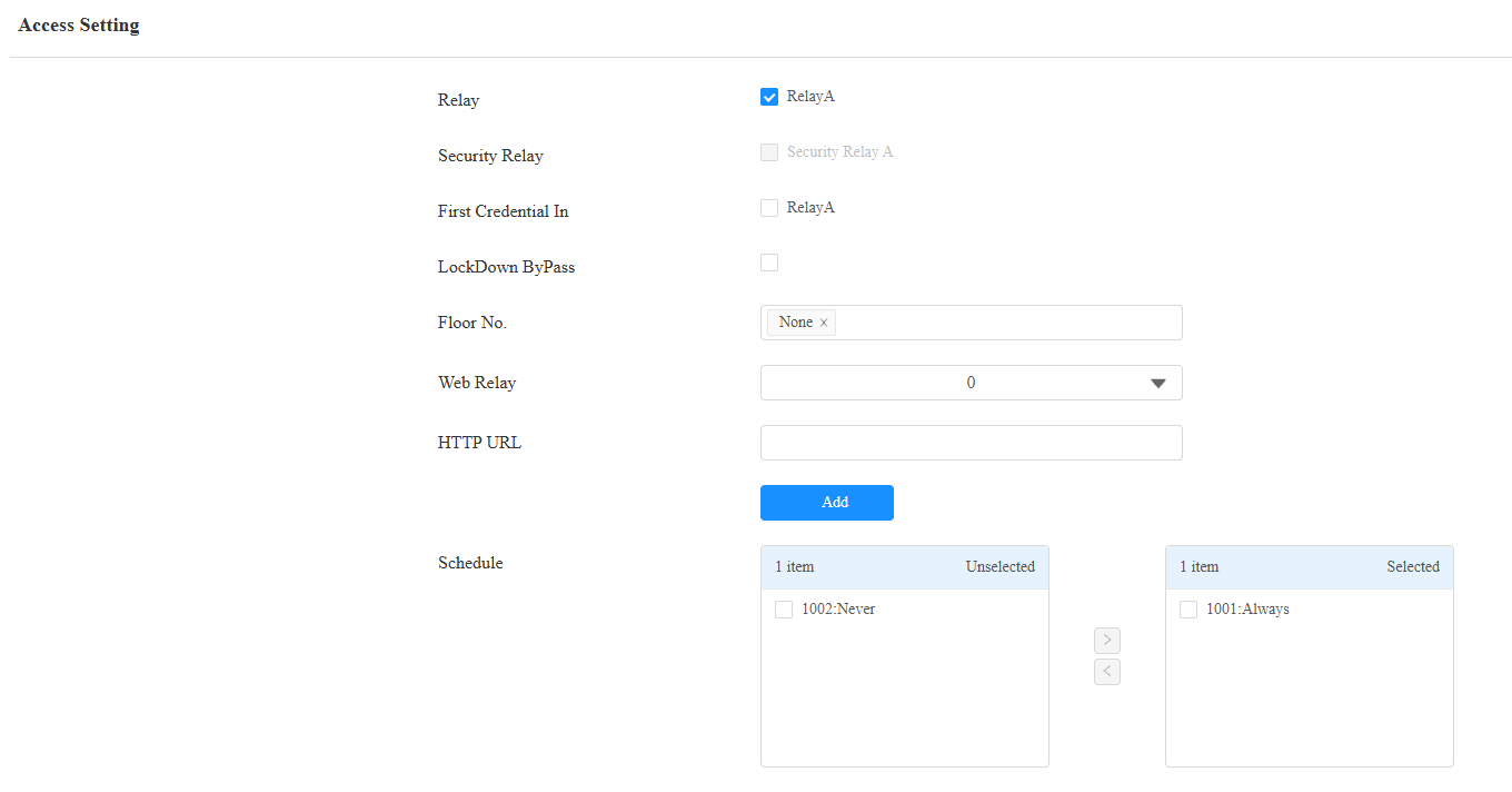
Relay: The relay to be triggered.
First Credential In: This decides whether the user can keep the door open during the scheduled time after activating it.
Lockdown Bypass: This decides whether the user can open the door when the door is locked during the scheduled time.
Floor No. : Specify the accessible floor(s) to the user via the elevator.
Web Relay: Specify the ID of the web relay action commands that you’ve configured on the Web Relay interface. A default value of 0 indicates that the web relay will not be triggered.
HTTP URL: Specify the HTTP URL sent to another Akuvox device for door opening. You can add up to 10 commands.
Schedule: Grant the user access to open designated doors during preset periods by relocating the desired schedule(s) from the left box to the right one. Besides custom schedules, there are 2 default options:
Always: Allows door opening without limitations on door open counts during the valid period.
Never: Prohibits door opening.
Import/Export User Data
El teléfono de entrada permite que los datos de usuario o el control de acceso se compartan entre los teléfonos Akuvox mediante importación y exportación, mientras que también puedes exportar los datos faciales desde el teléfono y luego importarlos a un dispositivo de terceros.
Haz clic aquí para ver cómo importar y exportar datos de usuario entre teléfonos puerta Akuvox.
To set it up, go to Directory > User interface. The device supports up to 20,000 users.
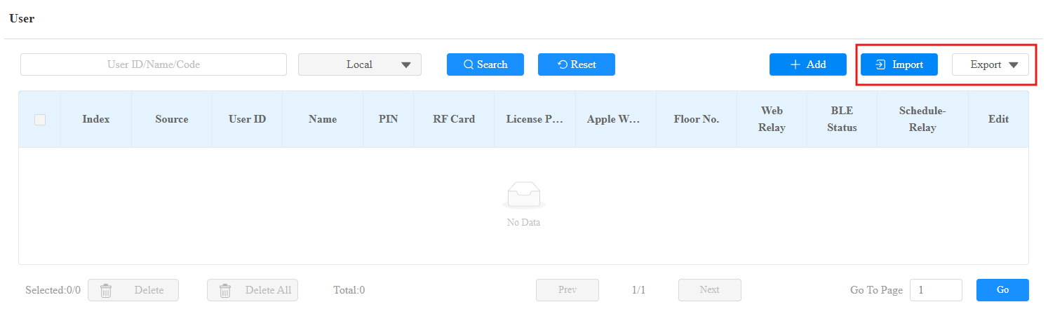
Import: Format:.tgz/.xml, size: < 2.8MB (Each .xml file); Format:.csv, size: < 18MB.
Export: The supported format is CSV or XML.
Contactless Smart Card
Puedes seleccionar una tarjeta NFC o una tarjeta Felica para acceso sin contacto. Por ejemplo, si activas tanto las tarjetas NFC como las Felica, puedes obtener acceso sin contacto con ambos tipos de tarjetas.
To set it up, go to Access Control > Card Setting > Contactless Smart Card interface.

Enabled: Select from Disabled, NFC, Felica, and NFC & Felica.
Note
The NFC feature is not available on iPhones.
Click here to view how to open doors via NFC.
Mifare Card
El dispositivo puede leer tarjetas Mifare cifradas para mayor seguridad. Cuando esta función está activada, lee los datos en los sectores y bloques designados de las tarjetas, no el UID.
Haz clic aquí para ver los detalles sobre cifrar y leer las tarjetas Mifare.
To set it up, go to Access Control > Card Setting > Mifare Card Encryption interface.
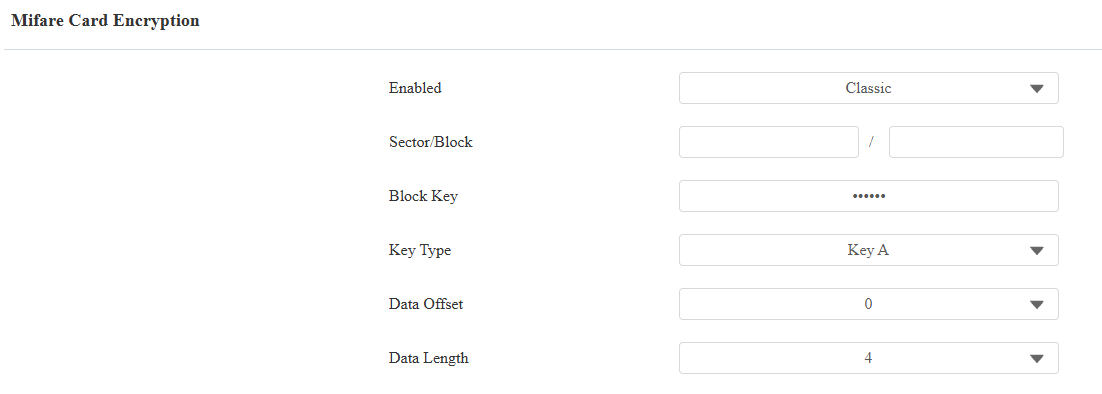
Classic:
Sector/Block: Specify the location where encrypted card data is stored. A Mifare card has 16 sectors (numbered 0 to 15), and each sector has 4 blocks (numbered 0 to 3).
Block Key: Set a password to access the data stored in the predefined sector/block.
Key Type: Specify which authentication key is used when accessing the Mifare Classic card sector.
Data Offset: Define from which byte position to start reading data, with a range of 0 to 16. The default is 0. It is used together with Data Length to determine the full data extraction range.
Data Length: Define the length of valid byte data, with a range of 1 to 16. The default is 4.
Plus: You can set up three choices. This means you can use three types of Mifare Plus cards. When swiping a card, as long as one of the choices matches its SL key, the card code in the block you specified will be output.
Block: Specify the block(s) to be read.
SL1: The key number within 32 bits.
SL3: The key number within 32 bits.
DESFire:
App ID: A 6-digit hexadecimal number
File ID: The ID of the encrypted file of the app, which can be a number from 0 to 16.
Crypto: The encryption method.
Key: The file key.
Key Index: The index number for the key, which can be a number from 0 to 11.
Byte Order: The byte reading order. The default is MSB. The device starts reading bytes after performing the Data Offset and Data Length.
MSB: Most Significant Bit means the reading order is normal(from left to right).
LSB: Least Significant Bit means the reading order is reversed(from right to left).
Data Offset: Define from which byte position to start reading data, with a range of 0 to 43. The default is 0.
Data Length: Define the length of valid byte data, with a range of 1 to 8. The default is 4.
CEPAS Card Reading
The device supports reading CEPAS cards. Under the CEPAS functionality module, there are two toggle options available: CSN (Card Serial Number) and CAN (Card Number).
Select the card reading mode on the Access Control > Card Setting > CEPAS interface.

CSN: The default option. This option allows the device to read the UID (Unique Identifier) of the CEPAS card, which is a unique value assigned to each card.
CAN: This option allows the device to read the card number stored on the CEPAS card, which can be used for identification or access control.
Unlock by HTTP Commands
El dispositivo soporta desbloqueo remoto de puertas mediante un comando HTTP. Simplemente habilita esta función e introduce el comando HTTP (URL) para el dispositivo. Esto activará el relé y abrirá la puerta, incluso si los usuarios están lejos del dispositivo.
Set it up on the Access Control > Relay > Open Relay Via HTTP interface.
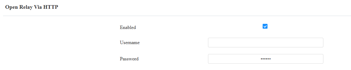
Username: Set a username for authentication in HTTP command URLs.
Password: Set a password for authentication in HTTP command URLs.
Tip
Here is an HTTP command URL example for relay triggering.

Note
The HTTP format for relay triggering varies depending on whether the device's high secure mode is enabled. Please refer to the how-to guide Open the Door via HTTP Command for more information.
Unlock by Exit Button
Cuando los usuarios necesitan abrir la puerta desde dentro pulsando el botón de Salida, tienes que configurar el terminal de Entrada que coincida con el botón de Salida para activar el relé de acceso a la puerta.
Haz clic aquí para ver el vídeo instructivo.
To set it up, navigate to Access Control > Input interface.
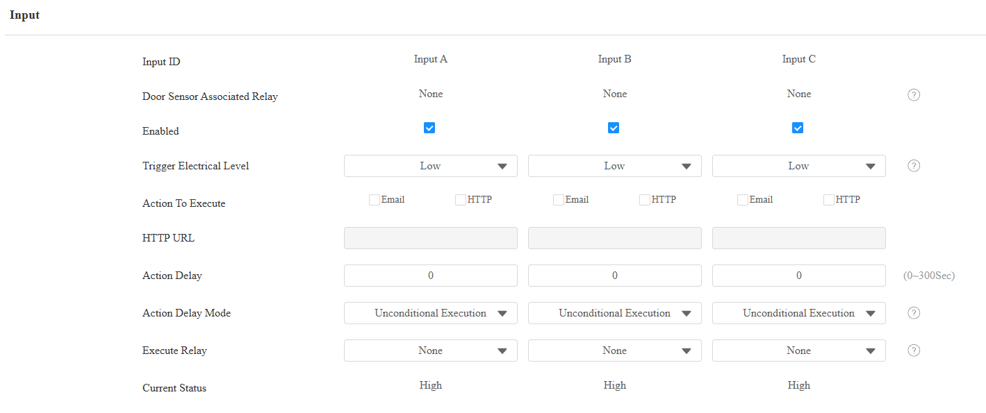
Door Sensor Associated Relay: This indicates the Relay bound to the Input when the Input is configured as a Door Sensor. Displays None when the Input is not associated with any Relay.
Enabled: To use a specific input interface.
Trigger Electrical Level: Set the input interface to trigger at a low or high electrical level.
Action To Execute: Set the desired actions that occur when the specific Input interface is triggered.
Email: Send a screenshot to the preconfigured Email address.
HTTP: When triggered, the HTTP message can be captured and displayed in the corresponding packets. To utilize this feature, enable the HTTP server and enter the message content in the designated box below.
HTTP URL: Enter the HTTP message if selecting HTTP as the action to execute. The format is http://HTTP server’s IP/Message content.
Action Delay: Specify how many seconds to delay executing the preconfigured actions.
Action Delay Mode:
Unconditional Execution: The action will be carried out when the input is triggered.
Execute If Input Still Triggered: The action will be carried out when the input stays triggered. For example, if the door stays open after triggering the input, an action such as an email will be sent to notify the receiver.
Execute Relay: Specify the relay to be activated on input trigger. This is incompatible with the break-in intrusion feature. The same input cannot work for both the door sensor and the push exit button.
Current Status: Display the status of the input signal.